so, me being a buffalo... I couldn't help but make a swipe at tightening up the gap... and using a reasonable AR guess...
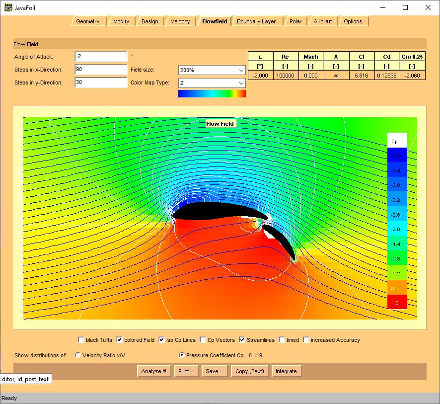
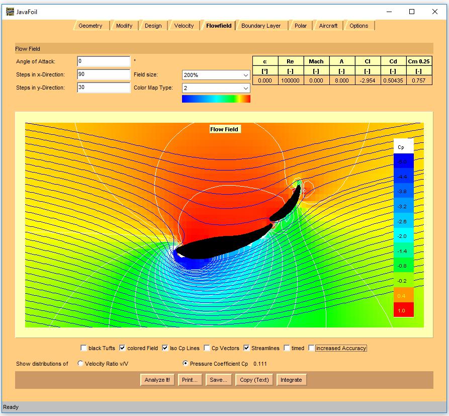
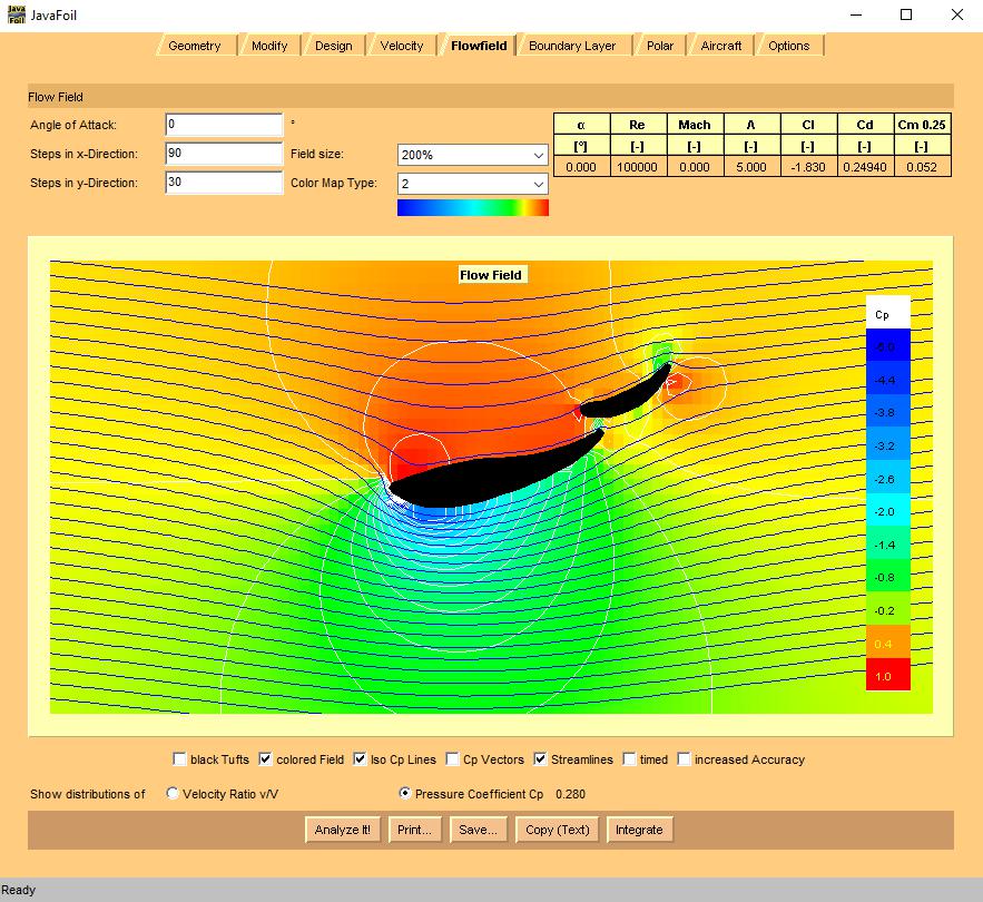
yes, drag is way up there... but that's almost entirely to do with the finite span that's applied. this would be what it would look like for your "2d" conditions above:
edit:
should I move this over to the Aerodynamics subforum now?
Why's the drag so different between those two plots?
Also, yes let's move to aerodynamics if you like!

Robbie (Forum Supporter) said:
Why's the drag so different between those two plots?
With you plots, you had the 'AspectRatio' (AR) on the 'Options' tab set to "0", which tells JavaFoil to calculate for an 'infinitely long' wing... i.e. 2D. A 56" span wing, that's ~11" in chord, has an actual AR of ~5. Although, there's nominal endplates, and this will be close to the ground. So, I've run mine at a 50% better AR... just as a guess.
When a wing has a 'finite' span, then there's two things that come into play. The wing-tip vortex reduces the maximum coefficient of lift the wing can produce. And, additionally, we can compensate for the 'induced drag', which is the drag due to lift... which has the span and/or AR as a component in it's calculation. This is added to the "profile" drag... which is kind of like the drag due to the section shape, and the skin friction (which is based on Reynolds number) to get the 'total' drag.
So, your calculation affectively finds the 'profile' drag of the section at that set of conditions. while, adding in a 'guess' AR allows JavaFoil to apply some "compensations for AspectRatio, which generally hold true", including a reduction in Cl_alpha due to wingtip vortex, and the induced drag.
That's also part of the reason why I tend to favor "wing tip mounts" only. That way the endplate is a mount (one thing doing two jobs), and the endplate connected to the body minimizes the 3D effect of the finite wing on 'negative lift' and drag. And that's before we even get to the whole "mounts on the underside of a car wing really screw up maximum downforce capability of the wing.
standard buffalo caveats:
iirc, ymmv, i reserve the right to be corrected by stafford1500, etc. 
also, I'm going to play around a bit with adding a 'simple bent aluminum sheet extension' virtually to the main section, and see if we can do a bit better.... since, I'm assuming this is for F-Dat, and as such you're not constrained by the usual rules.
it might take a day or two, though... I've gotta revamp the spreadsheet I have for generating that new section with the meganracing wing's main section.
I got to 6
~250#s of downforce, for ~70#s of drag... at 60mph
it's ugly as all get out... and who knows how realistic it is; but... I'll take it for a "first swipe"
also, let's assume the F-Dat is 56" wide and 30" tall, with a 2ft by 2ft box on top for the driver... thus ~15sqft of area; with a guessed coefficient of drag of a miata ~= 0.4
than, the base drag of the car, at 60mph is.... ~550#s.
is CoefL of 6 anywhere near realistic though? I thought FSAE wings generally made about CL about 3, just trying to keep this in perspective.
The end-plate mounts are a really neat idea though...
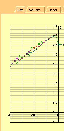
I got to about 4 with only playing around with the 'stock' shapes and their relationship in space. The good news is the AoA to CoefL is linear for a good 10-15 degree range of AoA - meaning you'd have adjustability.
CoefL to AoA in above config
Robbie (Forum Supporter) said:
is CoefL of 6 anywhere near realistic though? I thought FSAE wings generally made about CL about 3, just trying to keep this in perspective.
The end-plate mounts are a really neat idea though...
No, I don't think so. I think what's actually happening is that the increased length is raising the effective Reynolds number. Additionally, I think the areas of white mean the simulation is falling apart, and creating areas of incorrectly low pressure, which is boosting the Cl above what could occur in real life... without tripping some kind of error.
I'll suggest, though, that you want to scoot the second element in under the trailing edge of the main element. The nose of the second element wants to be in a particular place near and below the main element... thus the low pressure from the nose of the second element helps to pull the flow from the top side back to it while high pressure from the underside of the main element is pulled into the slot and "adds energy" to the flow keeping it attached to the upper surface of the second element.
There's an overview of some of this stuff: here
and, if you want to do more reading, the "codex of high lift aerodynamics" is an AIAA paper written from a "Wright Brothers Lecture" given by a Douglas A/C aerodynamicist "A.M.O. Smith". If you hunt around, you can probably find a copy of it.

Just catching up on your progress and I am pleased with it.
CL ~6 is doable, but you are going to be getting the range of operation pretty small at that design Lift Coefficient. so it could be really good then get really bad quickly, and happen in both directions with speed and other influences.
The aspect ratio corrections noted by Sleepyhead are the right sort of numbers to keep in mind. You can force JavaFoil to run the wing/car in ground effect too. You have to change the settings in the Options tab to set the ground at Y=0 and then move the wing up to its nominal position.
Between the Aspect Ratio and the Ground Effect corrections you can get a really good idea of how significantly the wing can perform, even at low speeds. Yes, the shape is not ideal, but for the cost vs effort the performance is significant.
By the way the closest "standard" profile for the main plane I found was 53A-1015 (?? from memory). That has a sharp trailing edge but the middle section begins to mimic what you have. Adjusting the shape of your found wings with sheet metal (even just a simple sheet extension of the lower surface) can have significant impacts, as shown by Sleepyheads experiments.
One other thing to keep in mind, is area matters as much as Clmax. This wing is "ok-ish" on area.
Another thought, hat tip to forum sponsor, is that 9LR sells offcuts from their main wings... for cheap. The longest length right now is 16"... but you could pick up four sections of this (hopefully) to string into a very large area dual element wing on either side of the central cockpit... out in clean flow.
In reply to sleepyhead the buffalo :
yeah, that area thing is where things like flat floors and diffusers shine - a small pressure differential x a huge area!
well, I offered the guy $100 on ebay and he countered $114, so I am soon going to be the proud new owner of a $114 megan racing wing.
In reply to AngryCorvair (Forum Supporter) :
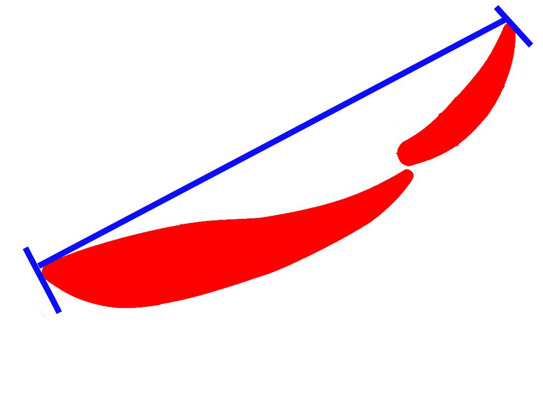
Here ya go you old grump.
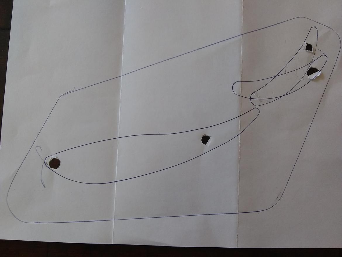
Obtained like this:
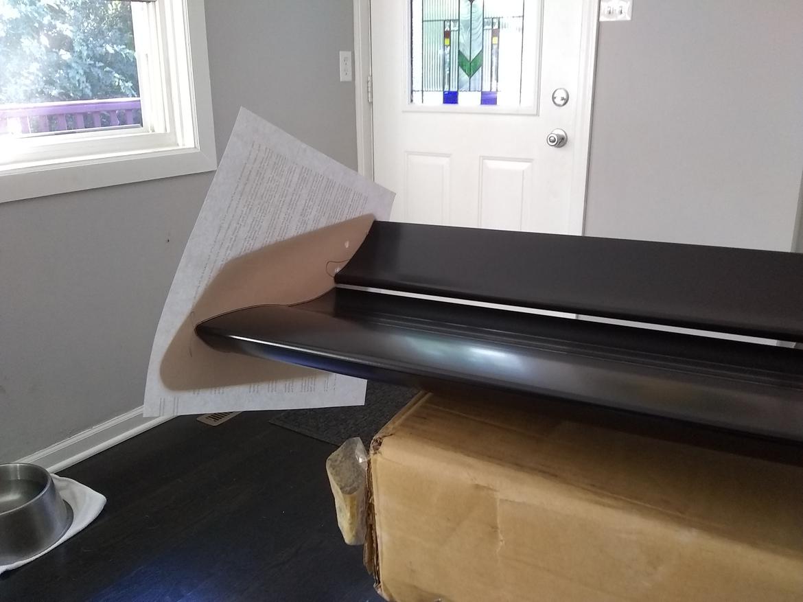
Also this one if you don't want the end plate:
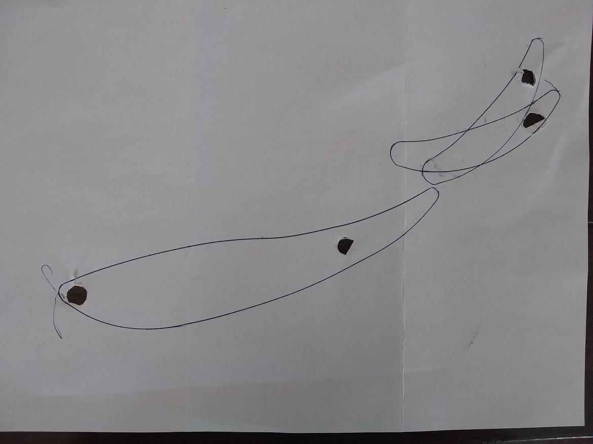
The rear foil mount is actually slotted and therefore can be adjusted anywhere between my two tracings.
I bet sleepy will have this all loaded up and analyzed before I have a chance to get dinner for the kids, but so far I actually think it could work pretty good right out of the box!
Robbie (Forum Supporter) said:
In reply to AngryCorvair (Forum Supporter) :
I bet sleepy will have this all loaded up and analyzed before I have a chance to get dinner for the kids, but so far I actually think it could work pretty good right out of the box!
It's a hectic week for this Buffalo, so it might not be until after your little ones have breakfast.
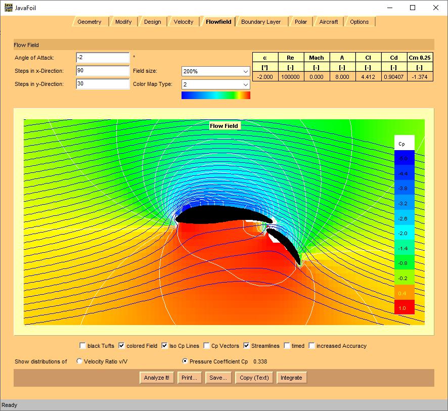
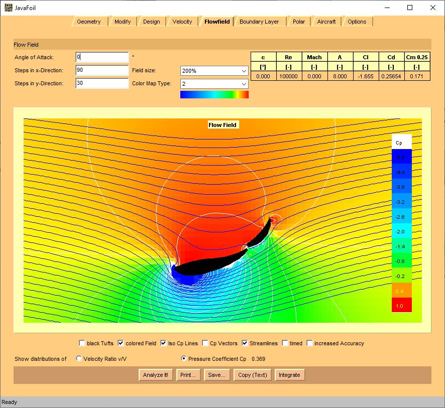
so, as delivered, it's probably good for a Clmax of 1.66:
but.... if you can rotate the assembly up 10deg...
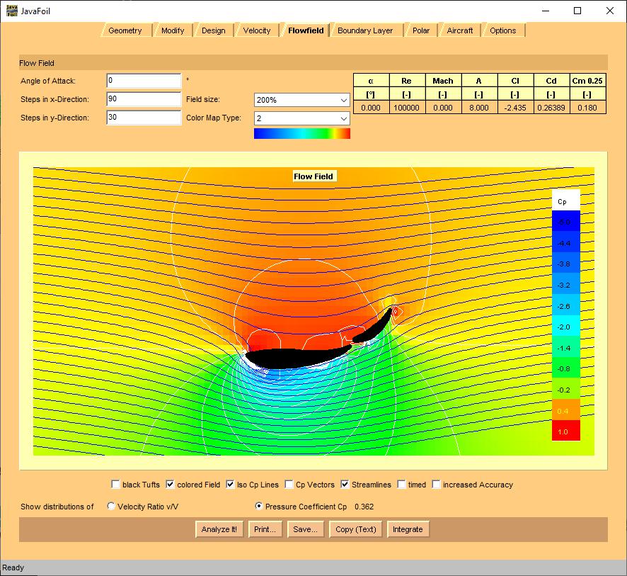
then 2.44 is possible
edit:
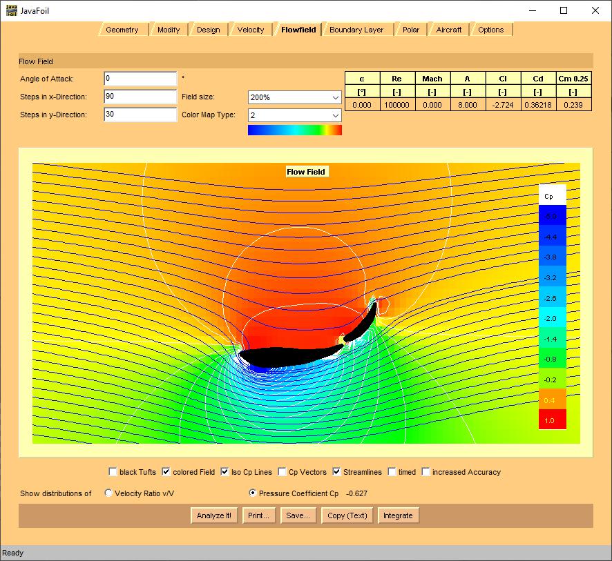
also, it looks like the angles are set by the enplates? if so, if you can move the main element down/forward a bit, and rotate the second element up 10deg more...
Cl = 2.7 is possible
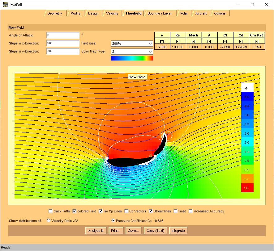
or... just shy of Clmax = 2.9 if you can tweak up the second element 20deg over stock:
edit #2:
F-Dat is going to have an easier time setting angles on the wing... since the lack of roof, and flat trunk ahead of the wing mean the in-flow into the wing should be "effectively horizontal".
Here's a question, is the AR of a dual element wing supposed to include the second element? Also, is the chord measured at the angle of attack?
yes, the endplates have holes that secure the foils. It would be easy to drill new holes to re-arrange the foils with respect to each other.
Robbie (Forum Supporter) said:
Here's a question, is the AR of a dual element wing supposed to include the second element? Also, is the chord measured at the angle of attack?
yes, the endplates have holes that secure the foils. It would be easy to drill new holes to re-arrange the foils with respect to each other.
Yes, for these purposes... I would include the length of the second element in your area calculation. One challenge of this is, that the effective area of the wing will change based on the angle of the second element related to the main element. Chord is usually defined as the distance from forward limit of the airfoil to the rearward limit of the airfoil... it gets a little funkier to see that as the effective camber of the foil exceeds 10%...
so, if the main element is 7.5" and the second element is 3.5" and they're pretty close to touching at the gap... then your chord length is on the order of 11". If the span is 56", then you're area is ~616sqin or 4.28sqft. Then your AR is 56^2 / 616 = 5... not including endplate effect, and ground effect.
Don't play the game, though, of thinking you'll "gain" area by making the gap bigger. And I wouldn't chase the AR part too much. If you want to maximize it... I'd suggest finding some cheap aluminum sheet a bit thicker than supplied and use it to make custom upright mounts... that way the uprights are doing 'two jobs', and you can grind off the mounts on the low pressure side and not get their downforce killing disruption
edit:
this also means (assuming standard day conditions)... that Cl = 2.5
Downforce.wing = 9.204 (lb/sqft) * 4.28 * 2.5 = 98#s
Ok, one more dumb question, how are you opening up both airfoils? I love the open button, but it always comes in as a single airfoil. The only way I seem to be able to create a second is by "duplicating" on the modify tab and then manually adjusting the duplicated airfoil.
Edit, I was able to load each individually, then copy the text, then paste them back in separately. So that seems to have worked.
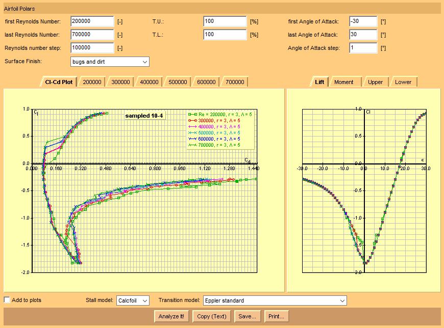
hmmm. I seem to be getting very different number from you. I wonder what causes that? I tried to match your settings as much as possible to get the "stock config". But I get this instead:
so, in JavaFoil, it wants coordinates in a ".dat" tab separated column list. I usually try to through a space after the tab, that way I can dual upload the coordinates into both JavaFoil and Xfoil. But, if you "save" a foil out of JavaFoil, it'll push them out in a tab separated column list.
to add a second element, you have to identify the additional elements by putting in a 'break'... which for JavaFoil is:
9999 9999
so, I tried sucking in the two outlines... and like you said, it came in as a single foil.
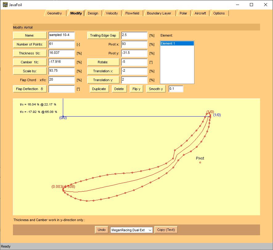
I saved that, and then manually edited them into two foils... but I mainly did that to get an idea of their relative "chord percent" sizes and 'where in % chord space' they ended up.

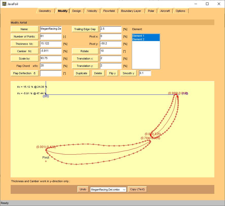
Then I pulled each element into JavaFoil separately, saved them separately... and then used that to generate a "combo" coordinates file with the two elements, both at 100%.
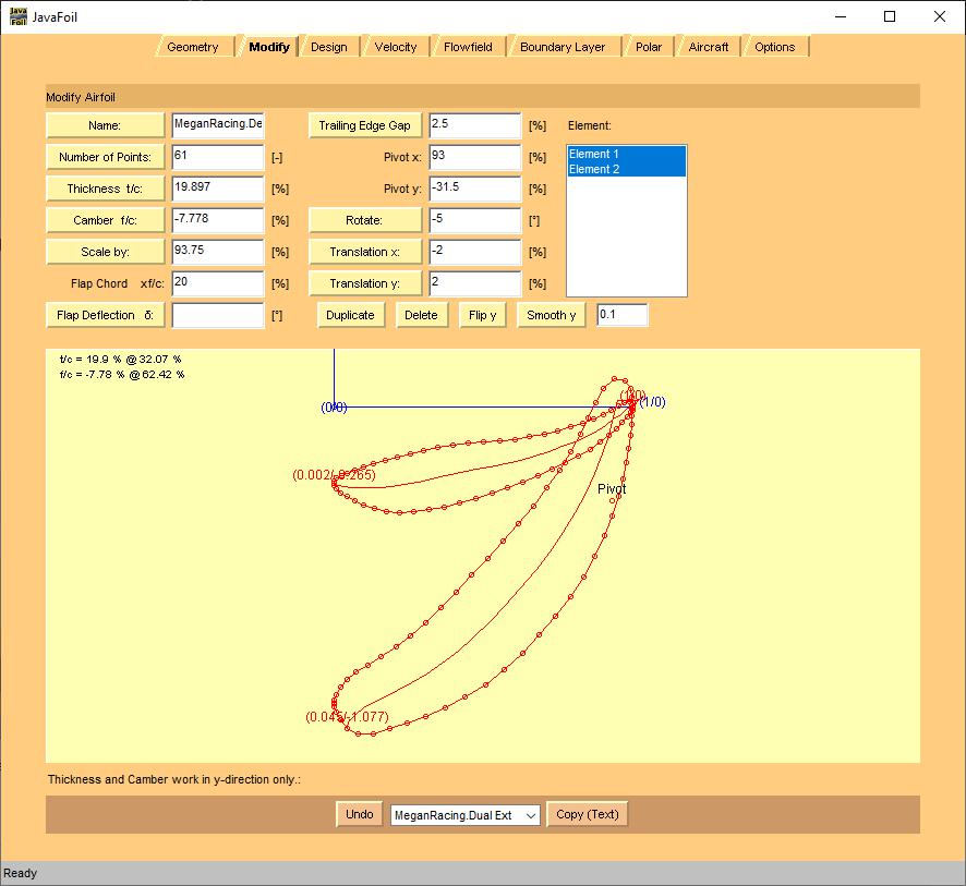
Then, I used JavaFoil to 'scale' them to their respective sizes (75% for the main foil, and 25% for the second foil)... and then used the 'Translate X' and 'Translate Y' functions to drop them into the place that the "unified single foil' indicated they'd be at:
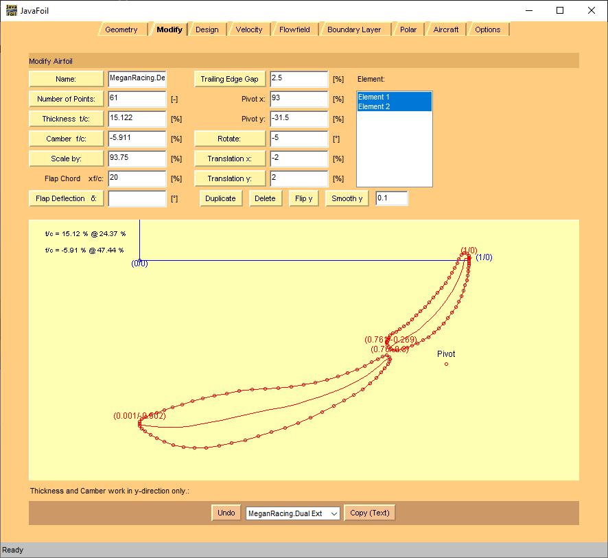
and, yes, I saved coordinate files for each of those steps along the way in descriptive filenames... which is why/how I was able to regenerate each of those steps with screen shots.
cue Daylan with the "Nerds!" meme
Robbie (Forum Supporter) said:
hmmm. I seem to be getting very different number from you. I wonder what causes that? I tried to match your settings as much as possible to get the "stock config". But I get this instead:
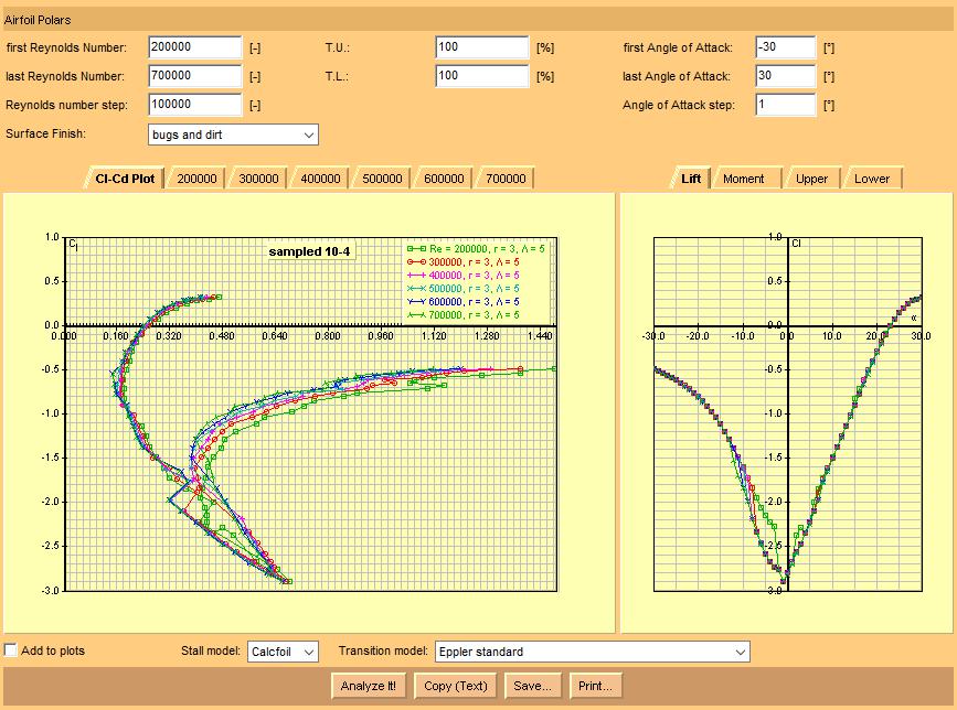
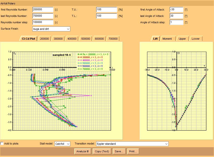
So, in the Polar tab...
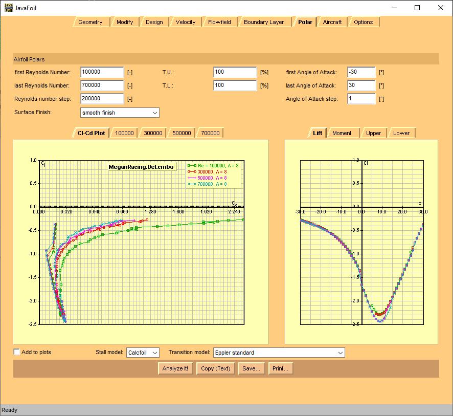
I'm using the 'Calcfoil' Stall model, and 'Eppler standard' ... Transition model. The transition model primarily determines drag (effectively), and Calcfoil/Eppler dropdown choice relates to Clmax. I use the Calcfoil because it gives more conservative Clmax (i.e. stall) behavior estimates. Also, the gap could have a significant impact on the lift coefficient. So, if you have it tighter than I do, that might be part of the difference (on top of the different stall model).
Ok, just saving some data:
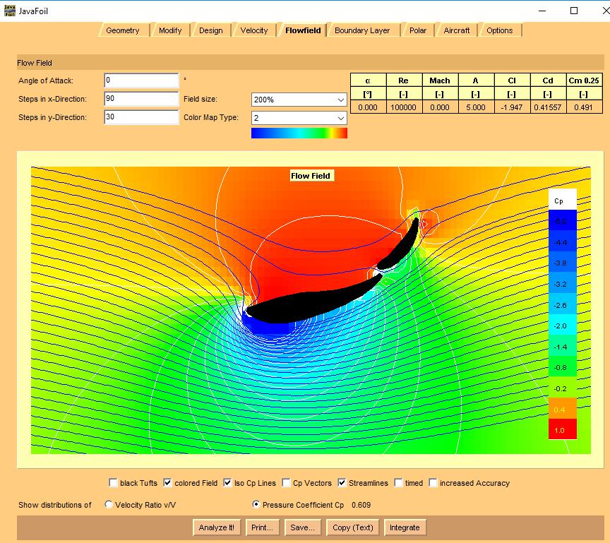
Stock wing (low rear foil angle)
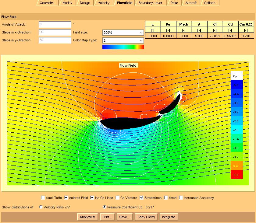
Stock wing (high rear foil angle) - notice it almost doubles drag, but hardly affects the downforce at all
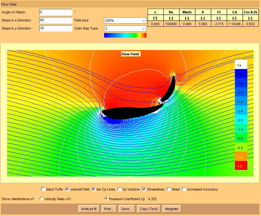
Stock wing (high rear foil angle, laid back 10 degrees) - this improvement suggests that the stock angle is effectively stalled
Increasing the rear foil angle by 20 degrees does increase the downforce significantly again, but the wing gets even more peaky, and the unsmoothness of the graph suggests the wing might really be in a stall mode.
Robbie (Forum Supporter) said:
Ok, just saving some data:
Increasing the rear foil angle by 20 degrees does increase the downforce significantly again, but the wing gets even more peaky, and the unsmoothness of the graph suggests the wing might really be in a stall mode.
One thing, I'd suggest you use "NACA standard roughness" instead of "bugs and dirt".
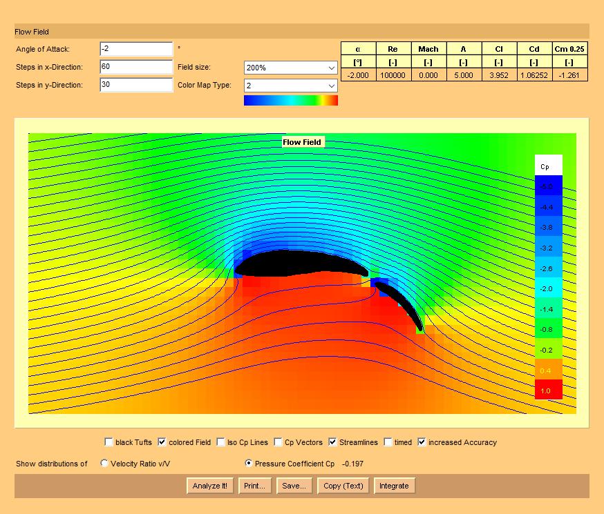
also, I banged around with this some. And the reason you're getting that sharp spike is because the second element is "too far" over the main element. I think the stock 61 points it used for a section, plus the placement of the second element, and the "weird" roundness of the trailing edge of the main section... are resulting in that peak (at an over-estimate of Clmax)... and as a result, the second element wants to be back a bit from the main section:
and it'll give a lower, but more rounded Clmax. That's part of the reason I've advocated for slapping some kind of extension onto the top side of that main element (preferrably something with a slight bend to it)... doing that means the nose of the second element has to do less of turning of the flow to match the curvature of the second element's low-pressure side.


