Presented by Nine Lives Racing
TXratti
TXratti Reader
2/24/23 8:11 a.m.

Up until now, there hasn't been any ducting or baffling to my radiator /intercooler stack. It hasn't been a problem but the car also has only seen autocross and hillclimb conditions with short duration runs, and I do plan on going to the track this year. I have noticed that even in TX summer, it was ok in traffic and stop go, around town, but above around 45-50mph, the temps would climb a bit (but not to the point of overheating).

Front view. Cosworth grill gives an opening in the top, plus the slot above the bumper. Below the crash bar there are the other two openings.


Here you see the worst of the problem, the majority of the side of the cooling stack is just.. open. My theory has been that the resistance of two heat exchangers stacks the air up in front and it just goes around. 

This is the planned oil cooler location, behind the Intercooler, but above the radiator, biased towards the 'cold side'. 
If anyone has a suggestion for a better location, let me know. In terms of mounting and access to flow, this seemed to make the most sense to me.

I don't have a good photo of it, but there's the main crash bar, and then part of the grill / front structure (can be seen behind the bumper two pictures down), which are at two separate levels on the bottom side, both are C-sections facing aft. I plan on covering them like you see with the cardboard, but shaped more like the green drawn line. Most of the rest of the structure is planned to be flat plates on the sides, sealed together.


Front upper thoughts, cutouts are for the grill structure supports. Would seal to the backside of the grill otherwise.


With the grill on, through the opening. Sealing the top of the IC to the core support except where the oil cooler is.


The bottom edge would get an angled plate to seal it to the bottom of the bumper and the radiator, meeting up with the sides. (poorly drawn in green over the photo here).


Does this seem like a good plan?
Does anyone have any suggestions?
 may do the first iteration with the flat plates and seal the edges, and try to "duct" things better on a second iteration down the line.

TXratti
TXratti Reader
2/24/23 9:50 a.m.

Quick drawing in Paint, here's what a cross section along the Centerline looks like:
Purple on top is core support/hood slam panel
Black is oil cooler
Blue in front is intercooler
Blue behind is radiator
Brown is chassis mid support/ grill support
Gray is bumper crash bar
Red is Bumper cover
Light purple is Upper grill


And here with my proposed Baffling in green (sides are vertical flat plates), and maybe but probably not the gold, on the top between the bumper and the grill support:

In the areas where the oil cooler *isn't*, I plan on blocking the flow ahead of the intercooler as shown:

Keith Tanner
Keith Tanner GRM+ Memberand MegaDork
2/24/23 10:05 a.m.

Where does the hot air go? Don't Cossies have hood vents? You can get away with a pretty small inlet if you work on extraction. 

stafford1500
stafford1500 GRM+ Memberand Dork
2/24/23 10:05 a.m.

Adding the panels you described should help with cooling as you expect. Getting perfectly sealed inlet ducting is difficult with production car limitations like the bumper and structure. The more you can seal things up the better, but you will capture the majority of what you want with your first iteration.

After getting the panels trimmed/fitted/installed the performance should be noticeable on the amount of time the fan runs and how much more stable your intake temps are. After you get things dialed in the way you want, add foam or silicone the panel edges to the bumper inner face for the final bit of efficiency.

The temps you see around 45mph are a function of the power required and the thermostat trying to achieve max flow with the air bypassing the coolers. The ducting should show an improvement here. Keep in mind the aero loads on the panels you install will likely be fairly large, so anchor them well and/or add bracing/flanges for strength and use lots of small fasteners, not just a few large ones.

TXratti
TXratti Reader
2/24/23 10:29 a.m.

In reply to Keith Tanner :

Cossies have hood vents, but currently mine does not (Cossie grill on an XR4Ti). I feel like some sort of hood extraction is in my future.

From the first picture in the original post, I feel like a center extraction may work better than the cossie vents which were on the outer part of the hood, further back.

Toyman!
Toyman! GRM+ Memberand MegaDork
2/24/23 10:37 a.m.
Keith Tanner said:

Where does the hot air go? Don't Cossies have hood vents? You can get away with a pretty small inlet if you work on extraction. 

What he said.^^

Air exits are much more critical than intakes. Any pressure in the engine bay effectively blocks the radiator. 

Taking a pressure reading in front of and behind the radiator might be worthwhile. You can pick up a Magnehelic gauge reasonably inexpensively. 

TXratti
TXratti Reader
2/24/23 10:39 a.m.

In reply to stafford1500 :

Copy that! I was imagining sheet aluminum riveted together, which is captured by the bumper and or grill. Most of the panels seem to be supported on the backside by structure, except for the planned curved panel going from the bumper crash bar up, and the block off above the intercooler, that will direct air over to the oil cooler. The former, will likely have some sort of bracket on the structure at the back of the grill support/chassis bracing, and the latter will be riveted to the upper panel of the upper shroud, likely needing stiffening.

TXratti
TXratti Reader
2/24/23 10:41 a.m.

In reply to Toyman! :

Yes, definitely aware of needing an exit, but mostly wanting to solve the large open areas to the side of the radiator, and then scope creep lead me to some of the upper ducting ideas.

TXratti
TXratti Reader
2/24/23 10:42 a.m.
Toyman! said:

What he said.^^

You can pick up a Magnehelic gauge reasonably inexpensively. 

Or make one? (Kind of like a U-manometer like you'd use to balance carburetors?) 

Edit: pressure differential may be more than... 10 in of water, which would make this prohibitively large

TXratti
TXratti Reader
2/24/23 10:51 a.m.

In a time with less roll stiffness, but a clearer photo, I've always wondered what the flap under the car really did. If it was AT the bottom of the radiator, I'd imagine it was trying to create high pressure in front of it to improve flow, but it sits behind it, in the car... (see second photo edit of prior Paint drawing)


Where the brown is the front subframe (simplified), and the black is a fairly thick rubber flap attached at the top. 

sleepyhead the buffalo
sleepyhead the buffalo GRM+ Memberand PowerDork
2/24/23 11:16 a.m.

I know this cross-section isn't "to scale"... but it looks like if you could move things down, then the choke section between the core support and the top of the IC is close to 1/3 the height of the oil cooler.  So, Si think there'd be benefit to ducting it 'by itself', especially if that was linked up to the 'front part of a center exit of the hood (aided by inclining the cooler)...

then the bottom side of the oil cooler duct will hopefully act like a guide for the top exit flow for the IC out the center exit.

pulling things down could also help with the flow coming to the bottom of the radiator.  The way the duct is drawn in your initial drawing, the area is decreasing before it gets to the radiator, which will increase pressure on the front side of the radiator, which I think we want to avoid.

You'll probably want to put a 'bash bar' under the rad... but that'll also give you structure to put an exit duct from the bottom of the radiator that might help link the flow out of it "back" and/or maybe oit to the wheels (I.e. front flow fans).  There might be some lower radiator duct treatments you could make that could help increase the low pressure back the to help draw flow out/through the radiator/IC bottom section

TXratti
TXratti Reader
2/24/23 11:48 a.m.

In reply to sleepyhead the buffalo :

I'm not overly concerned with oil temp, once there's actually a cooler in the system, I don't have any qualms about using most of the flow of the intercooler into the oil cooler, but angling it may be a good idea to help direct extraction (especially adding a center hood vent). The hard part becomes mounting, where the bottom of the oil cooler would be floating in space and needing to have structure brought to it, or make the duct structural.

I'd likely do more like the fat pink line here:


Shimming the radiator down would require an intermediary bracket if it was much more than about half an inch, it's mounted on 'wings' to the bottom of the frame rail and the bolt is already fairly long. half an inch may be enough to align the bottom of the rad to the bottom of the bumper (minus the exterior flange).

sleepyhead the buffalo
sleepyhead the buffalo GRM+ Memberand PowerDork
2/24/23 11:50 a.m.

The way the duct is drawn in your initial drawing, the area is decreasing before it gets to the radiator, which will increase pressure on the front side of the radiator, which I think we want to avoid.

I mis-spoke here a bit.  The pressure on the front side of these is going to be "high" no matter what.  My main concern is, that by "scooping" with the duct at the bottom, that we'll be increasing velocity into the radiator.

the nature of this 12lbs of E36 M3 in a 4lb bag, means there really isn't the longitudinal distance for the ducts to try to slow down the flow and encourage longer air-to-exchanger interaction and heat-extraction.  So, I think the best that can be hoped for is that the incoming flow speed not be *higher* than vehicle speed;  hence having the bottom duct be close to 'level'.


TXratti
TXratti Reader
2/24/23 11:52 a.m.

In reply to sleepyhead the buffalo :

Yes, understood! That's part of why the classic "fighter jet" style expansion duct exists right? To slow the flow and make better use of the coolers. The top portion is doing a bit of that, the lower is really just trying to seal the radiator to the bumper. The outer corners meet the bottom of the core, and it just dips lower in the center because of how the bumper is shaped.

Keith Tanner
Keith Tanner GRM+ Memberand MegaDork
2/24/23 12:29 p.m.
TXratti said:

In reply to Keith Tanner :

Cossies have hood vents, but currently mine does not (Cossie grill on an XR4Ti). I feel like some sort of hood extraction is in my future.

From the first picture in the original post, I feel like a center extraction may work better than the cossie vents which were on the outer part of the hood, further back.

Right, it was the fact that your current inlet was intended to be used with hood vents that I was thinking about.

Don't assume that's necessarily the best place for outlets. You might find it to be more effective off to the side. Lots of fun there to be had with a magnehelic gauge.
https://youtu.be/MCXhU0IeyTg

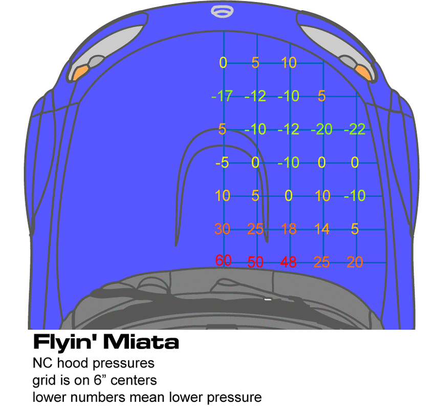
Here's a pressure map we did of a Miata a while back. The lower the number, the better a vent will work in that location.

TXratti
TXratti Reader
2/24/23 12:50 p.m.

In reply to Keith Tanner :

This is where my mind when when the gauge was mentioned. Map it out and see where's best.

Xratti
Xratti Reader
2/25/23 9:44 p.m.

Some CAD work to better describe what's going on:

jfryjfry
jfryjfry SuperDork
3/3/23 9:27 a.m.

I believe that dam under the car is to create a low pressure area behind it to help evacuate the engine bay - a gurney flap of sorts. 
 

also, if you want a nice, large hood vent, look at trackspec's c6 corvette gp2 vent.  I think that's what it's called.  It's big and might fit that space well.  It has an optional gurney flap that goes in front.  I have it on my c6 if you want pics

Xratti
Xratti Reader
3/24/23 8:39 a.m.

In reply to jfryjfry :

Yes! Please share what that looks like on your vette.
First iteration will be to add this ducting/baffling and no hood vent, but plan for the hood vent in the future as we get into summer.

jfryjfry
jfryjfry SuperDork
3/25/23 11:03 a.m.


I can get measurements of it later if you'd like. But it might be listed on trakspec's site. 

jfryjfry
jfryjfry SuperDork
3/25/23 11:08 a.m.

The gt500 hood vent was a popular add on for drift cars a few years back.  And I looked at a newer camaro hood vent before I got this one. 
 

the gt500 is wide but not as deep. In fact it might be too wide. 


Xratti
Xratti Reader
4/25/23 11:32 a.m.

I plan on doing a pressure plot of the hood like Keith Tanner showed in the Flyin Miata video: https://youtu.be/MCXhU0IeyTg?t=372

In the video it looks like you used a Magnehelic gauge with a range of 0-3" of H20, but I can't seem to find those (lots of 1", 0.5" but also 5.0" available). What units were the numbers in your pressure plot? From your experience what would be enough range to capture a hood pressure plot?


EDIT: Just found the ones on McMaster Carr with the different options. Still curious on max pressure differential you think would be useful.

VolvoHeretic
VolvoHeretic GRM+ Memberand Dork
4/29/23 1:11 a.m.
TXratti said:

The bottom edge would get an angled plate to seal it to the bottom of the bumper and the radiator, meeting up with the sides. (poorly drawn in green over the photo here).


Does this seem like a good plan?
Does anyone have any suggestions?
 may do the first iteration with the flat plates and seal the edges, and try to "duct" things better on a second iteration down the line.

Would an air scoop help direct air up into that bottom opening. Are you planning on putting a splitter under there? Looks good.

Xratti
Xratti Reader
5/10/23 10:35 a.m.

In reply to VolvoHeretic :

Currently no splitter, since still sort of targeting "Street" class for Gridlife/GTA (though very uncompetitive), but if I did it, would likely be paired with an air dam of some sort.


This was a sketch I made a while back:

You'll need to log in to post.

Our Preferred Partners
klYjMtu5kuGJ6by8QI4uqhw7yS4pStdGTsMtG267YQjRPagUlgd4gKHjsdBCaIL1