The rear spoiler is a focal point on a lot of 2nd gen F bodies and very easy to see. Since they're 35-45 years old now most have deformed or been damaged over time. The plastic slowly drying out and shrinking causes them to become wavy and crack. Some are worse than others of course and I'm lucky the two I'm working with were in pretty good condition to start with.
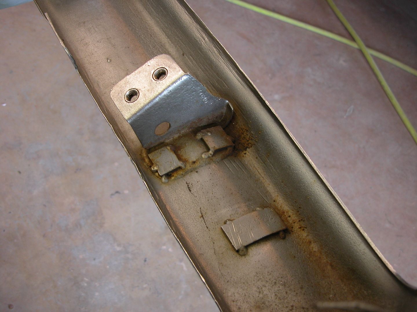
The tall one I'm making was from a 76 and needed some stripped threads repaired and missing studs replaced so I welded some small washers on 1/4" X 20 threaded rod and made several replacement studs (since I couldn't buy any locally). While I was making them I made the threaded part that screws into the spoiler a little bit longer to grab virgin threads at the bottom of the holes. Several drops of fiberglass resin in the holes before installing the new studs carefully and problem solved.
Next issue with spoilers is getting them to line up as well as we'd like. Often we're dealing with used or aftermarket quarters, deck lids, tail panels etc. which may not be the same as original. Our standards for panel alignment and gaps has raised quite a bit over the years since these cars were new and even when new the alignment/gaps weren't all that great from the factory. Here's my way of bringing old rear spoilers back to usable condition with better fitment and gaps than stock. I'm sure others have different ways of accomplishing the same goal and there's more than one right way to do things.
Strip the spoiler with 80 grit and clean old paint, sealers etc off the inside of the spoiler around the mounts and pads it sits on where it meets the body. Then install center section on trunk lid (trunk lid aligned previously). Clean old paint, sealers etc off the inside of the spoiler where it meets the body. If the mounts on the inside of the spoiler have to be modified by grinding a little off so the spoiler sits nice, so be it. Also, the holes in the decklid may need to be ovalized a bit to get the center section where you want it. Once happy with the center section, snug up the nuts on the ends to hold it in place. Then install end caps and see if you can get them lined up pretty well with the center section with the nuts snug. Again, may need to slot holes or modify the inside of the spoiler cap so it sits nice on the fender. Be patient, take your time and shuffle the pieces a little one way or another to get the pieces to sit as nice as possible on the sheetmetal and have the best gaps. If necessary move the center section a little and try again, when satisfied tighten the nuts. Then...
The ends of the caps and center section have often been sanded for previous repaints and the plastic has shrunk and deformed so after 35-45 years they're usually not very flat anyway. Apply a coat of your favorite body filler over the gaps between the end caps and the center section, don't try to fill the entire void, just bridge the gap. Ya, I know, it just seems wrong. Then use a hacksaw to cut a slot centered where you'd like the center of the finished body gap between the center section and end caps to be. Next use a thin file like a saw and cut the gap wider. Then use thicker and thicker files to widen the gap till it looks the way you want. Using the files keeps the slot straight and even because they don't flex much. If you want to move the gap a bit one way or another just apply pressure to the file as you're cutting with it. Once you've got the gap where you like it open the trunk and apply filler to the voids on the ends where the filler used to bridge the gap didn't go. Then close trunk and use the file again, repeat as needed till the ends just have little voids and pinholes in the bondo.
[URL=http://s240.photobucket.com/user/NOTATA/media/The%2014%20Car%20Performance%20Therapy/014_zpsrseyplp2.jpg.html]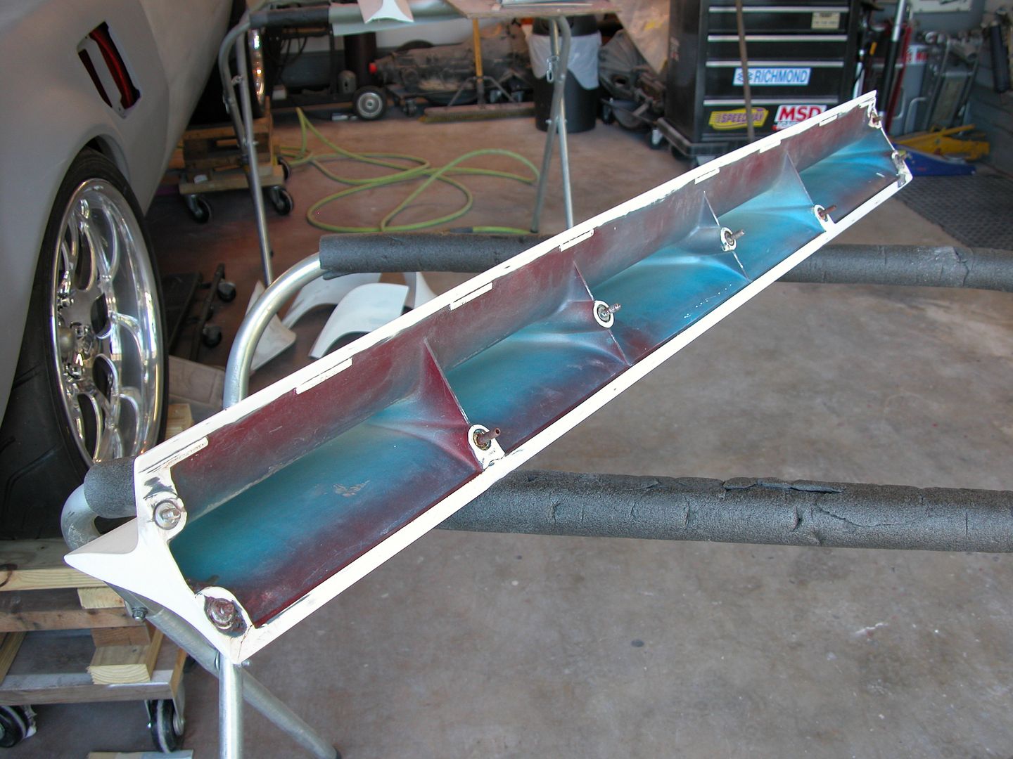 [/URL]
[URL=http://s240.photobucket.com/user/NOTATA/media/The%2014%20Car%20Performance%20Therapy/001_zpsyz5ldb0i.jpg.html]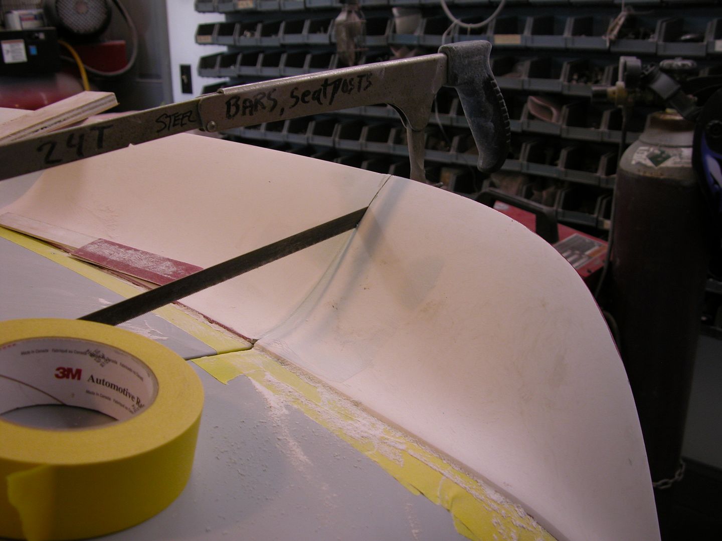 [/URL]
[URL=http://s240.photobucket.com/user/NOTATA/media/The%2014%20Car%20Performance%20Therapy/004_zpsbauskiaw.jpg.html]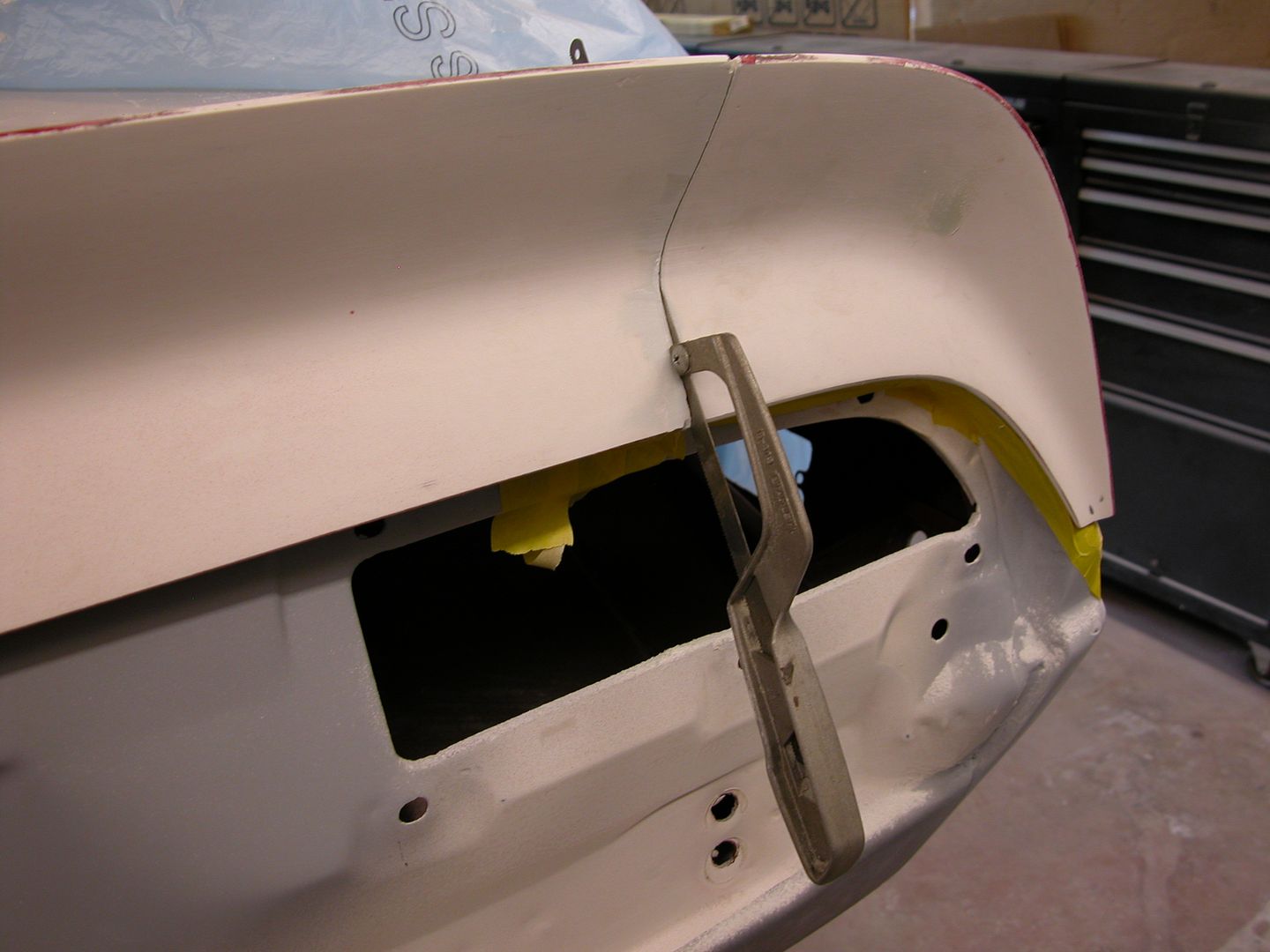 [/URL]
[URL=http://s240.photobucket.com/user/NOTATA/media/The%2014%20Car%20Performance%20Therapy/003_zps7oabplke.jpg.html]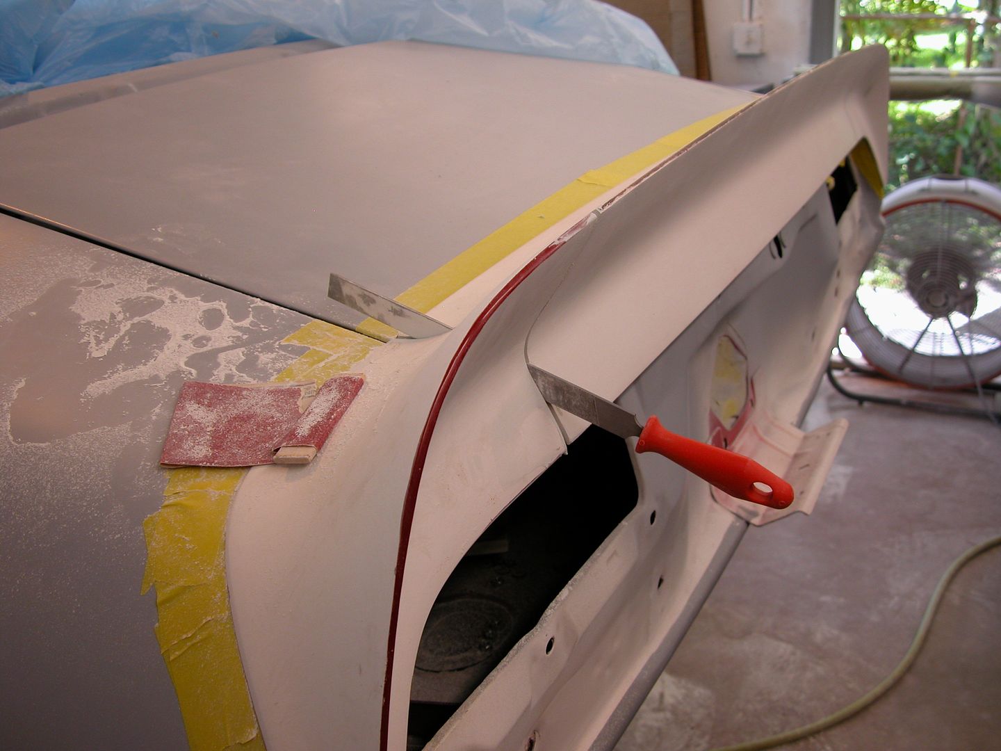 [/URL]
Because the spoiler plastic has shrunk, warped etc. over the years They're not straight anymore. At a minimum they'll need high build primer and block sanding. I'd hoped that would be all I needed to do for the one below but as you can see after some blocking on the one in the pic below I've already cut through the primer to the plastic and haven't even removed the guide coat in the low areas where the mounts hold the spoiler to the car. This was on a spoiler that spent 99% of the last 25 years in a garage since I did the car the first time. I've seen the same pattern before and apparently the mounts pull enough so the spoilers deform as the plastic gets old. The cure is to skim coat the whole spoiler with filler (front and back) then block sand the filler with the spoiler attached to the car so you can have the center section line up with the end caps by sanding across the gap. then prime/block/prime using a guide coat till you're happy.
[URL=http://s240.photobucket.com/user/NOTATA/media/The%2014%20Car%20Performance%20Therapy/002_zpsx2bi8dxt.jpg.html]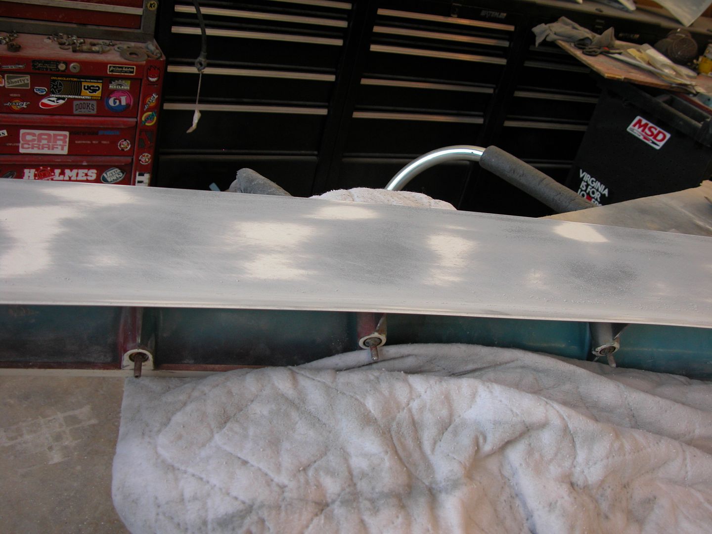 [/URL]
[URL=http://s240.photobucket.com/user/NOTATA/media/The%2014%20Car%20Performance%20Therapy/004_zps2egplfwe.jpg.html]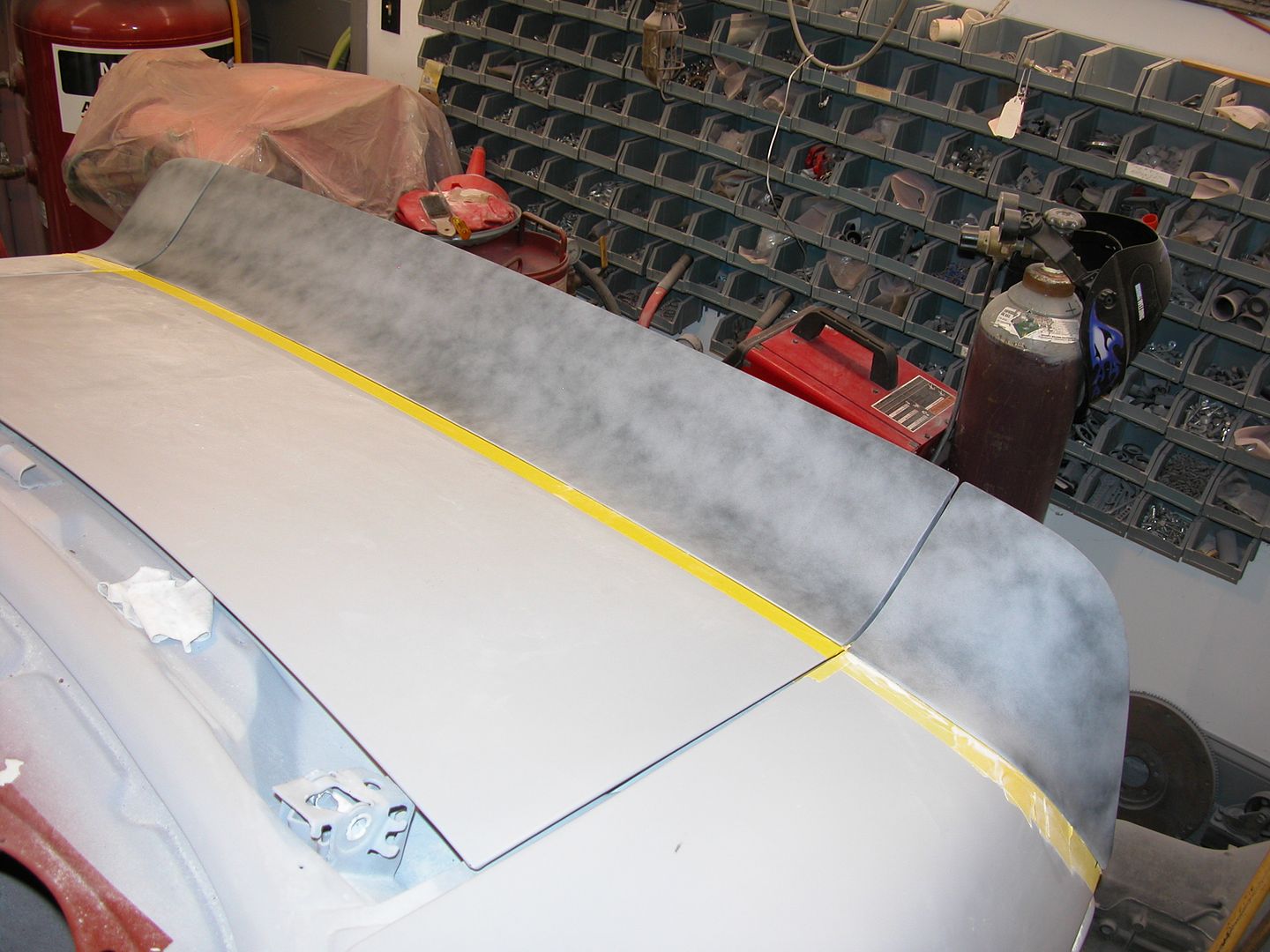 [/URL]
Here's my tip for making a uniform edge where the spoiler flows into the decklid. A flat block with sticky sandpaper and a spacer to keep the block on the same angle as you slide across the spoiler. Don't forget tape so you don't mess up the trunk lid.
[URL=http://s240.photobucket.com/user/NOTATA/media/The%2014%20Car%20Performance%20Therapy/011_zpswp4brt6e.jpg.html]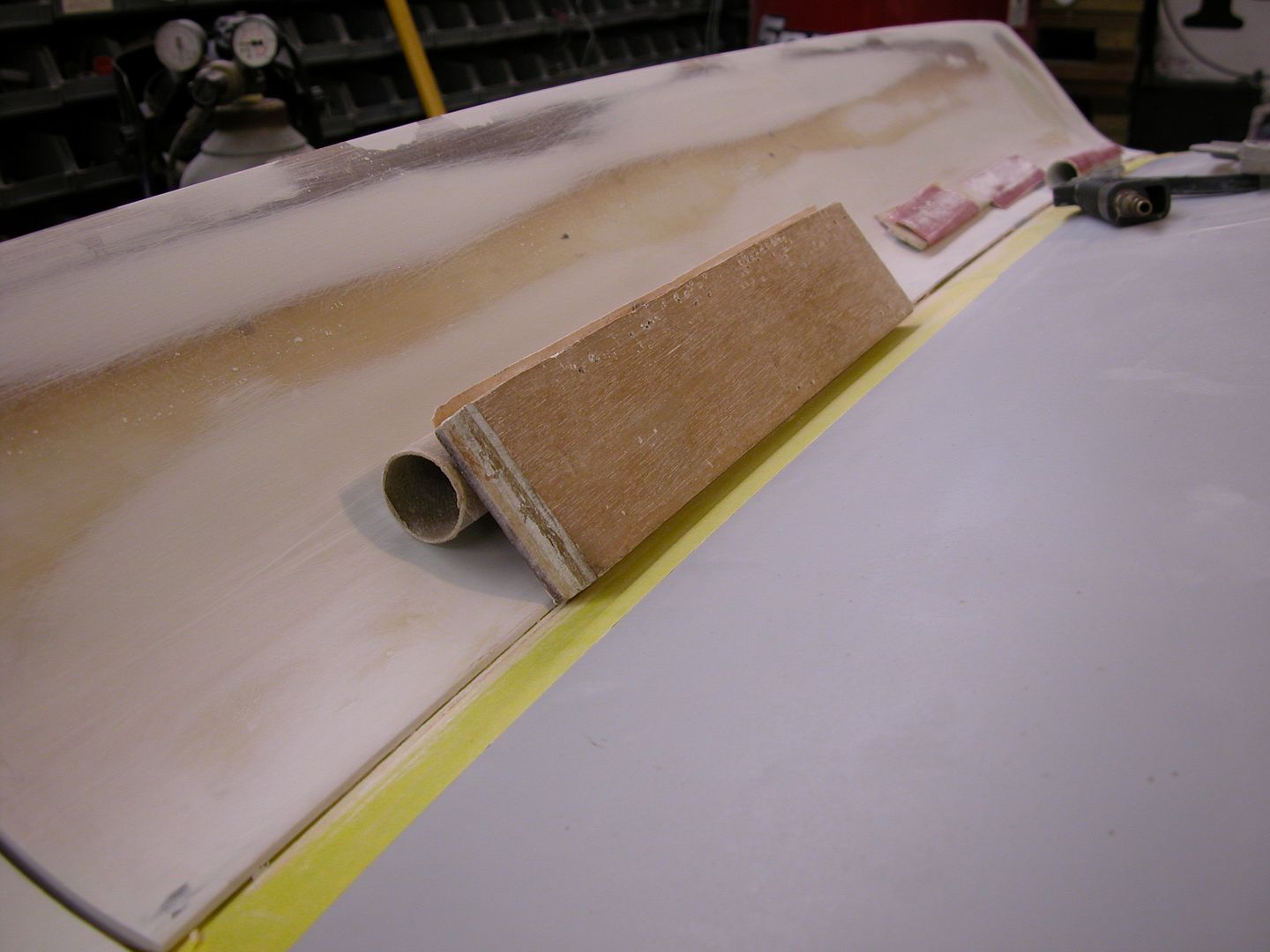 [/URL]
I've now got both spoilers in final primer and will move on to other things. When I mounted them to do my sanding etc. I mounted the stock spoiler forward and the tall spoiler slightly back so that the stock spoiler would always cover any foot print marks, or fade lines from having the tall one. The tall version is about 1 1/4" taller than stock and mounted to the car in the pics below where it will stay a while so I can admire it while doing other stuff ahahaha.
[URL=http://s240.photobucket.com/user/NOTATA/media/The%2014%20Car%20Performance%20Therapy/003-14.jpg.html] [/URL]
[URL=http://s240.photobucket.com/user/NOTATA/media/The%2014%20Car%20Performance%20Therapy/002_zpsgxhlvwij.jpg.html]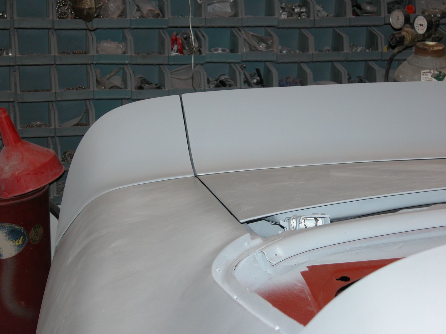 [/URL]
[URL=http://s240.photobucket.com/user/NOTATA/media/The%2014%20Car%20Performance%20Therapy/012_zpsumajthan.jpg.html]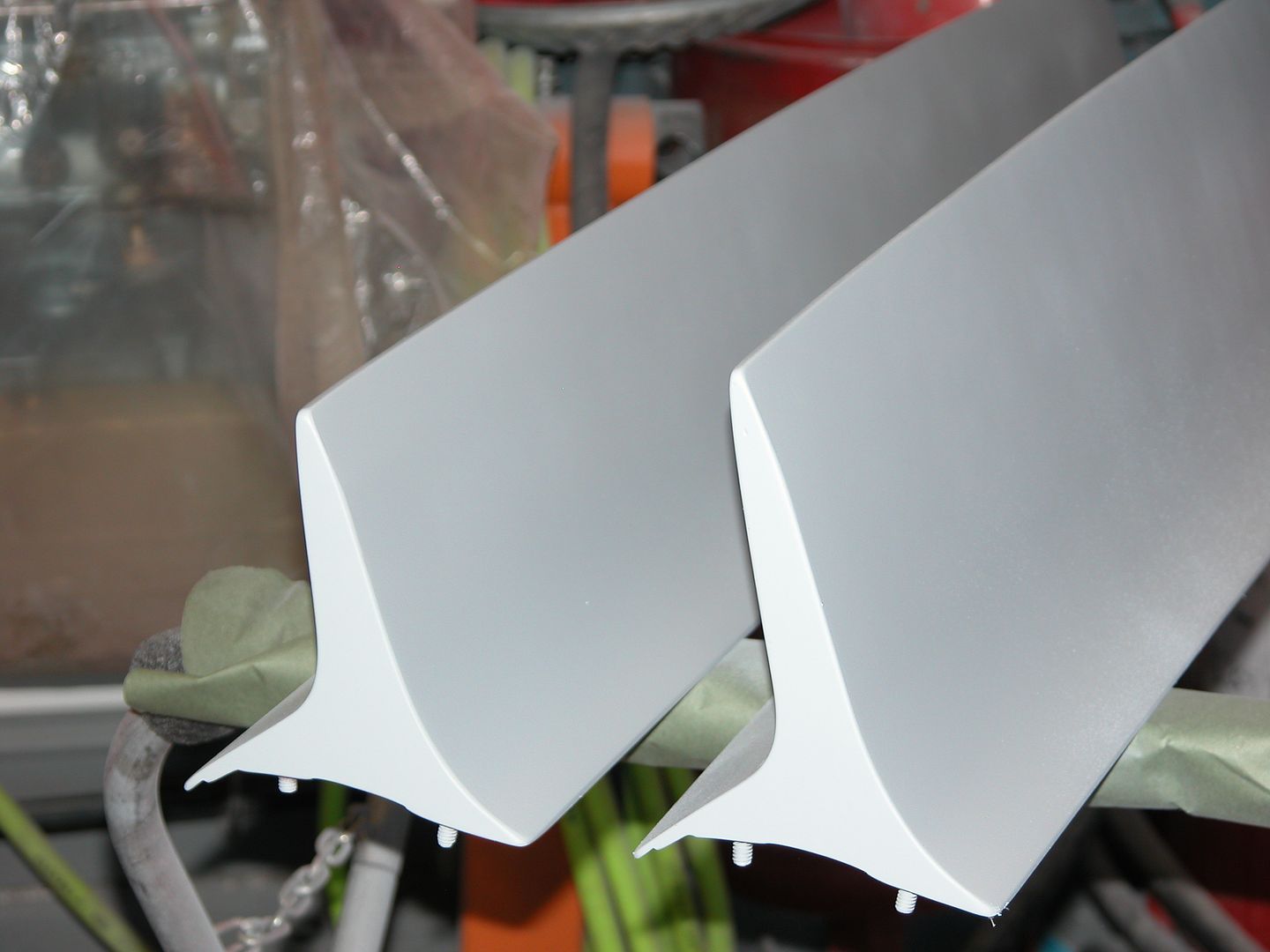 [/URL]
[URL=http://s240.photobucket.com/user/NOTATA/media/The%2014%20Car%20Performance%20Therapy/003_zpskqe4qxgc.jpg.html]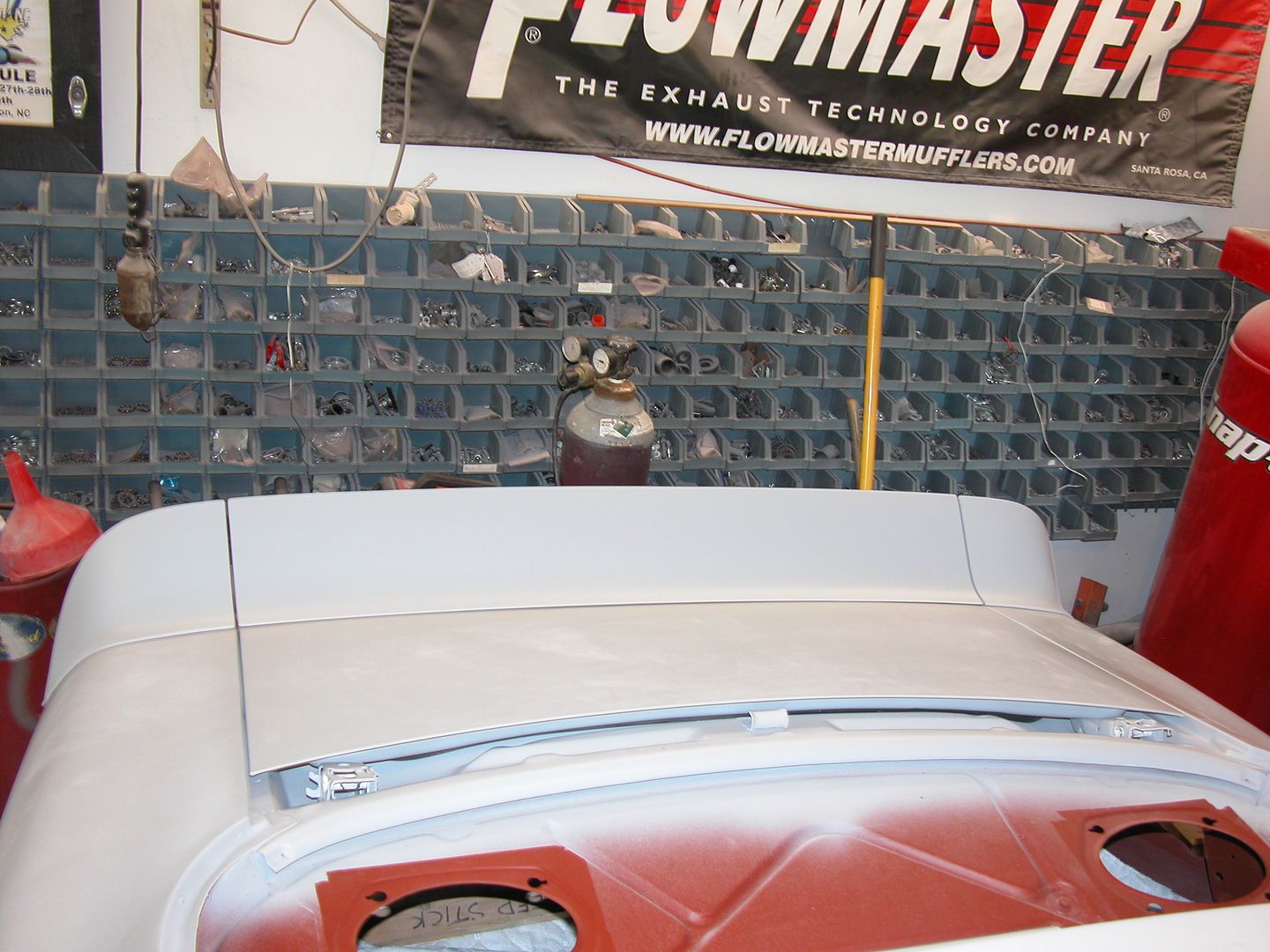 [/URL]
[URL=http://s240.photobucket.com/user/NOTATA/media/The%2014%20Car%20Performance%20Therapy/008_zpsziniqqbj.jpg.html]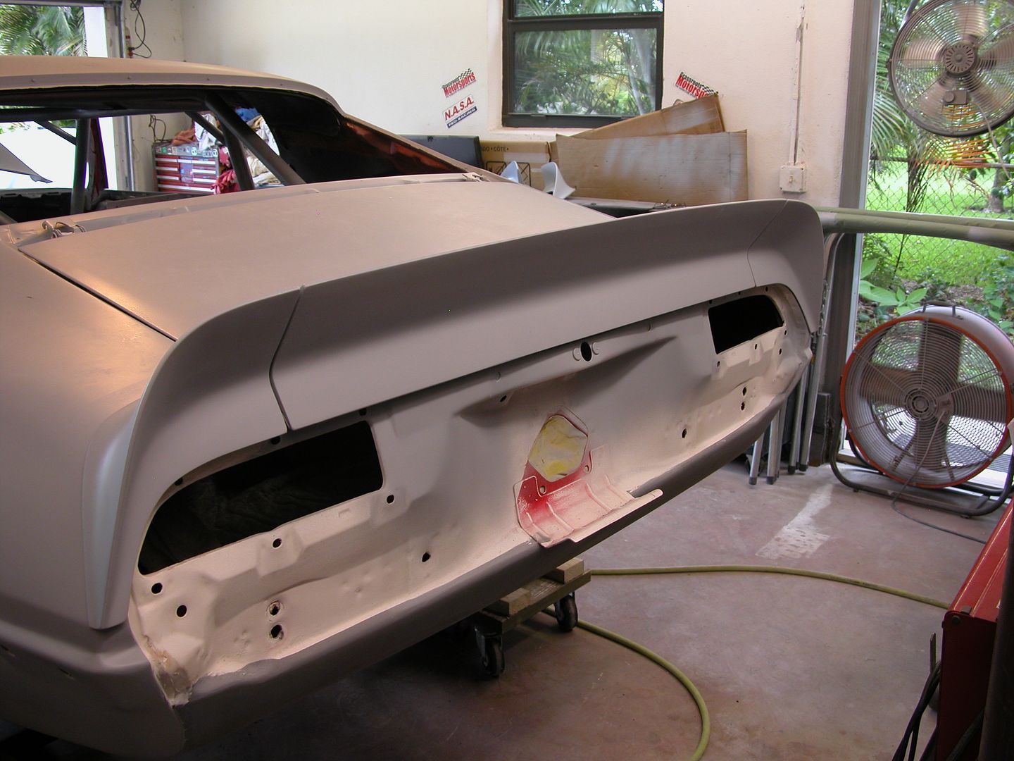 [/URL]
[URL=http://s240.photobucket.com/user/NOTATA/media/The%2014%20Car%20Performance%20Therapy/011_zpsw4ehsaak.jpg.html] [/URL]


 [/URL]
 [/URL]
 [/URL]
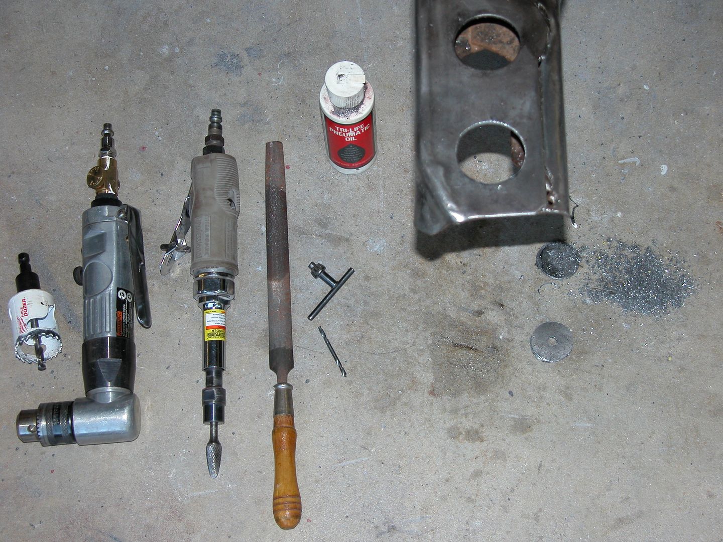 [/URL]
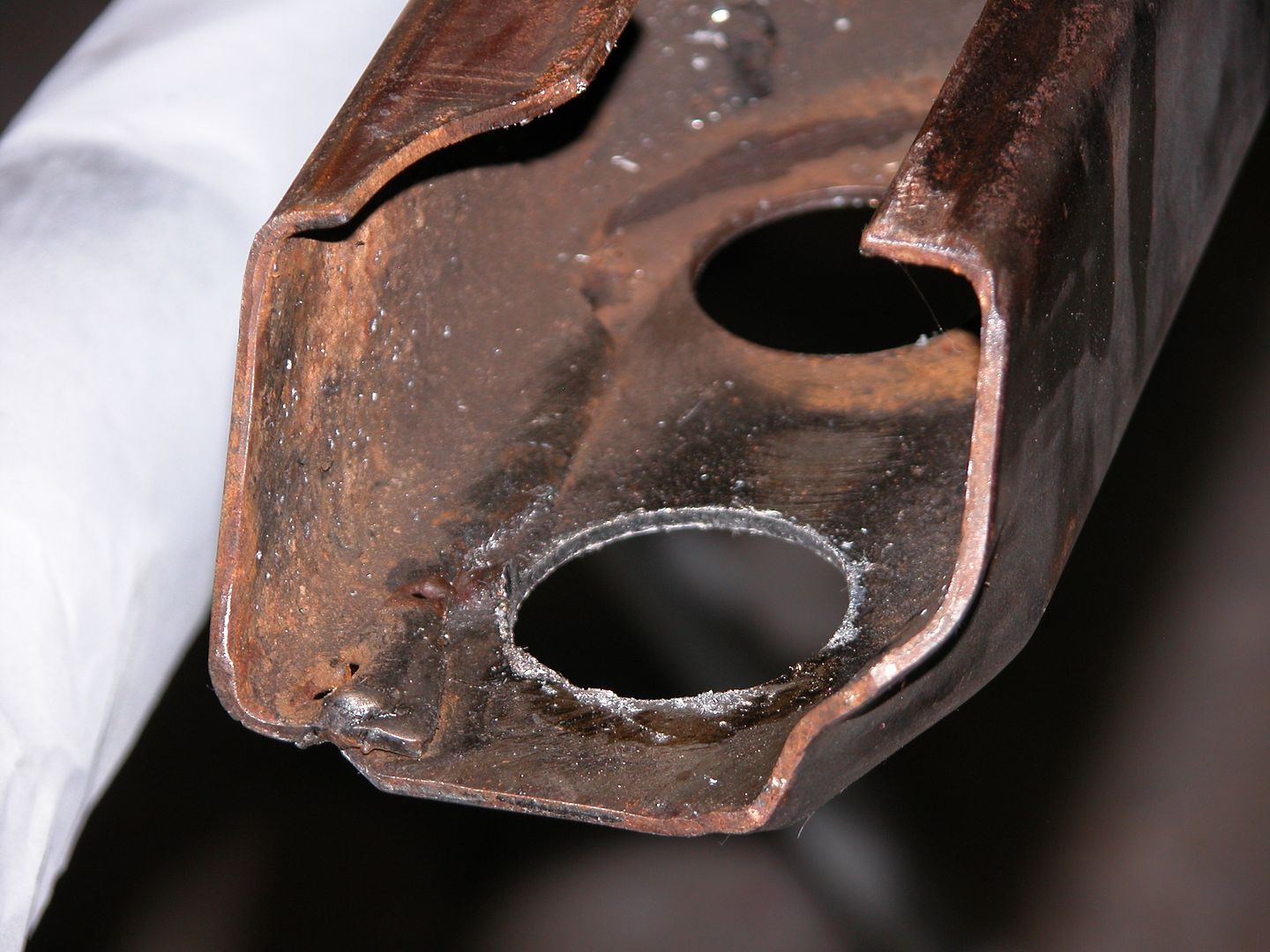 [/URL]
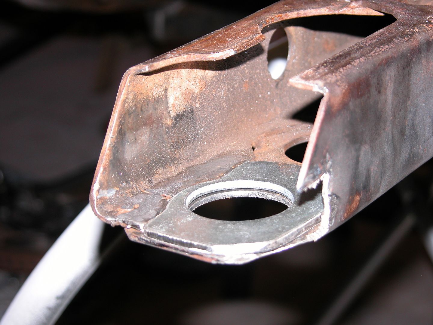 [/URL]
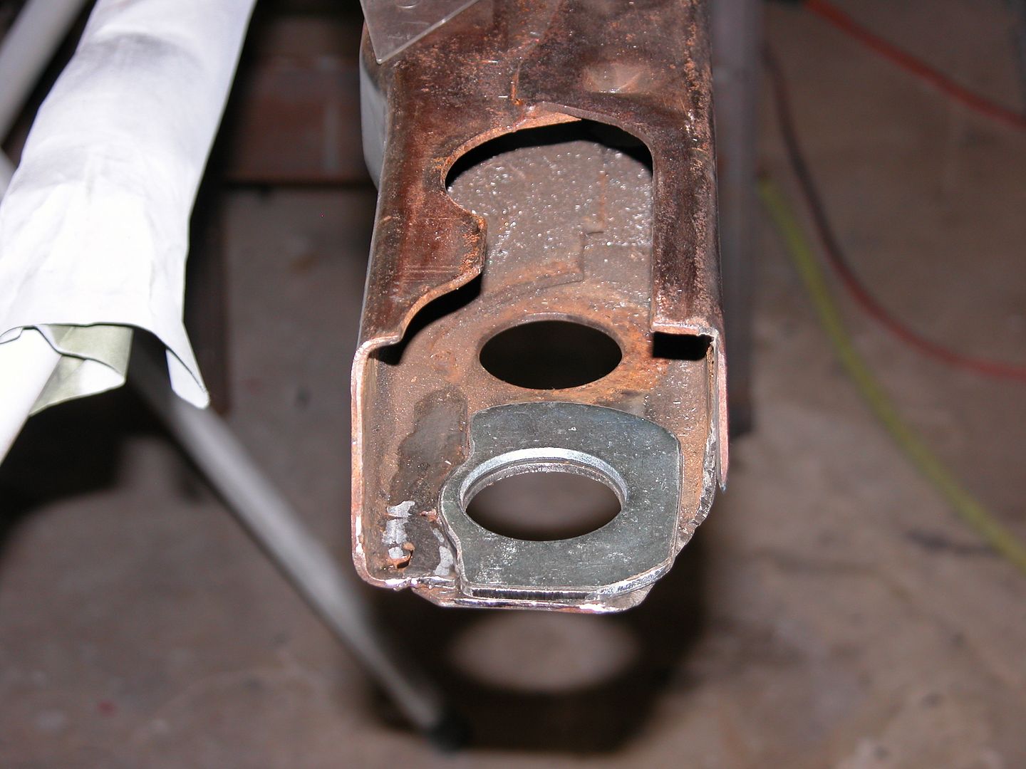 [/URL]
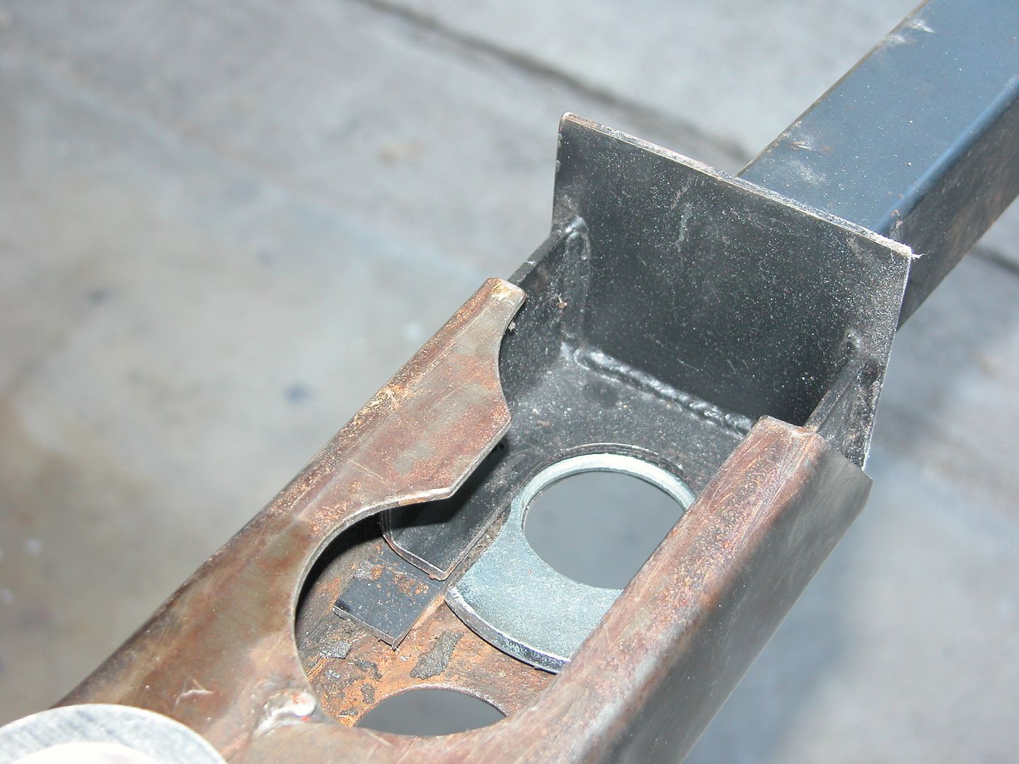 [/URL]
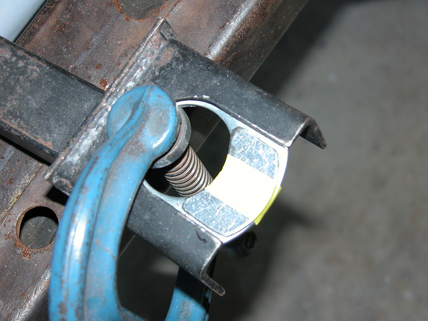 [/URL]
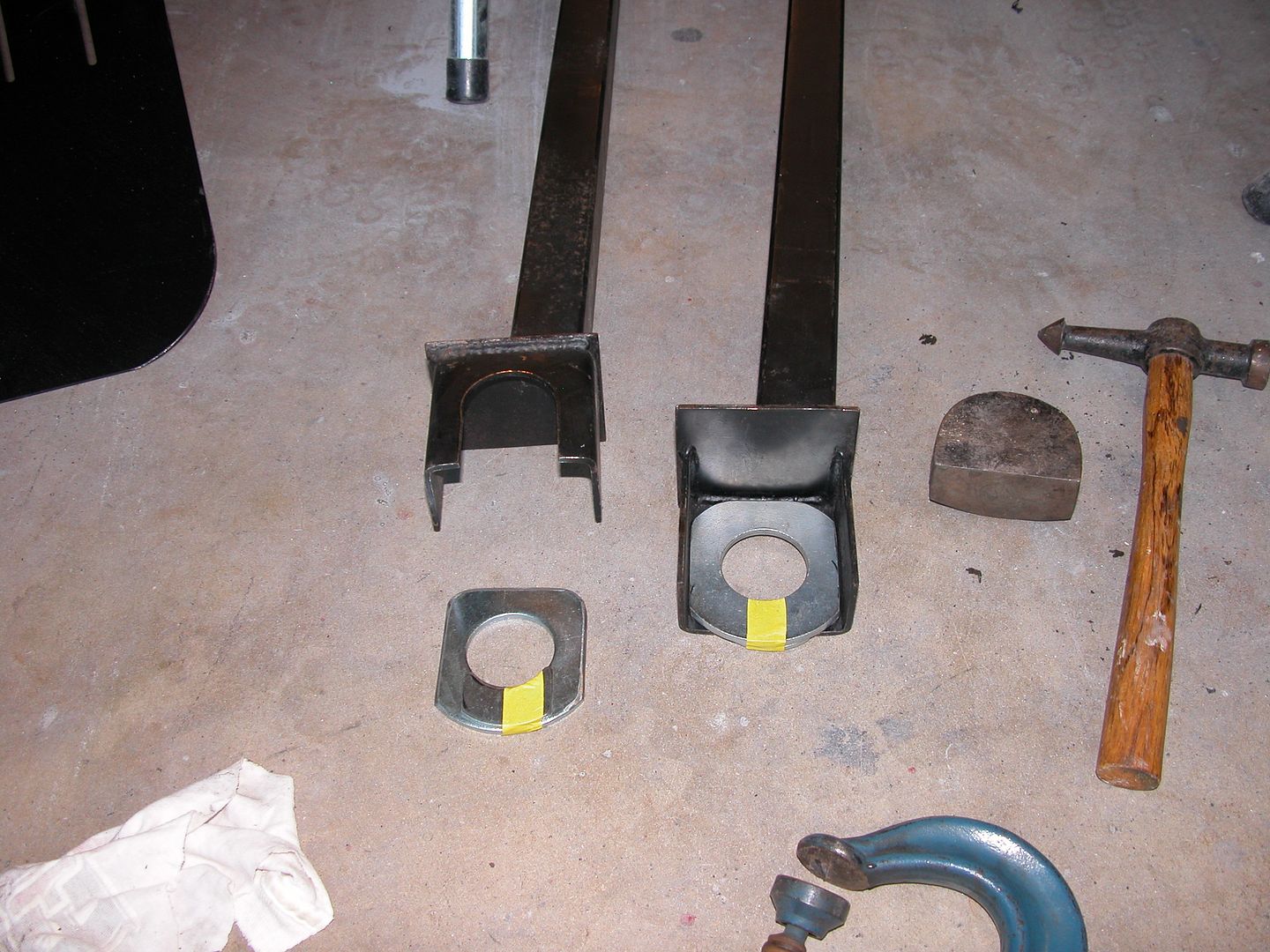 [/URL]
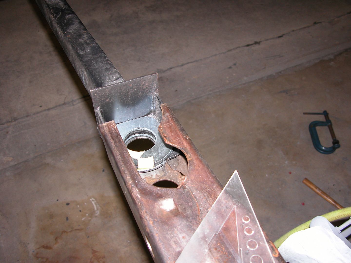 [/URL]
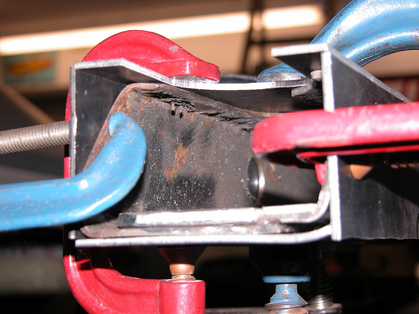 [/URL]
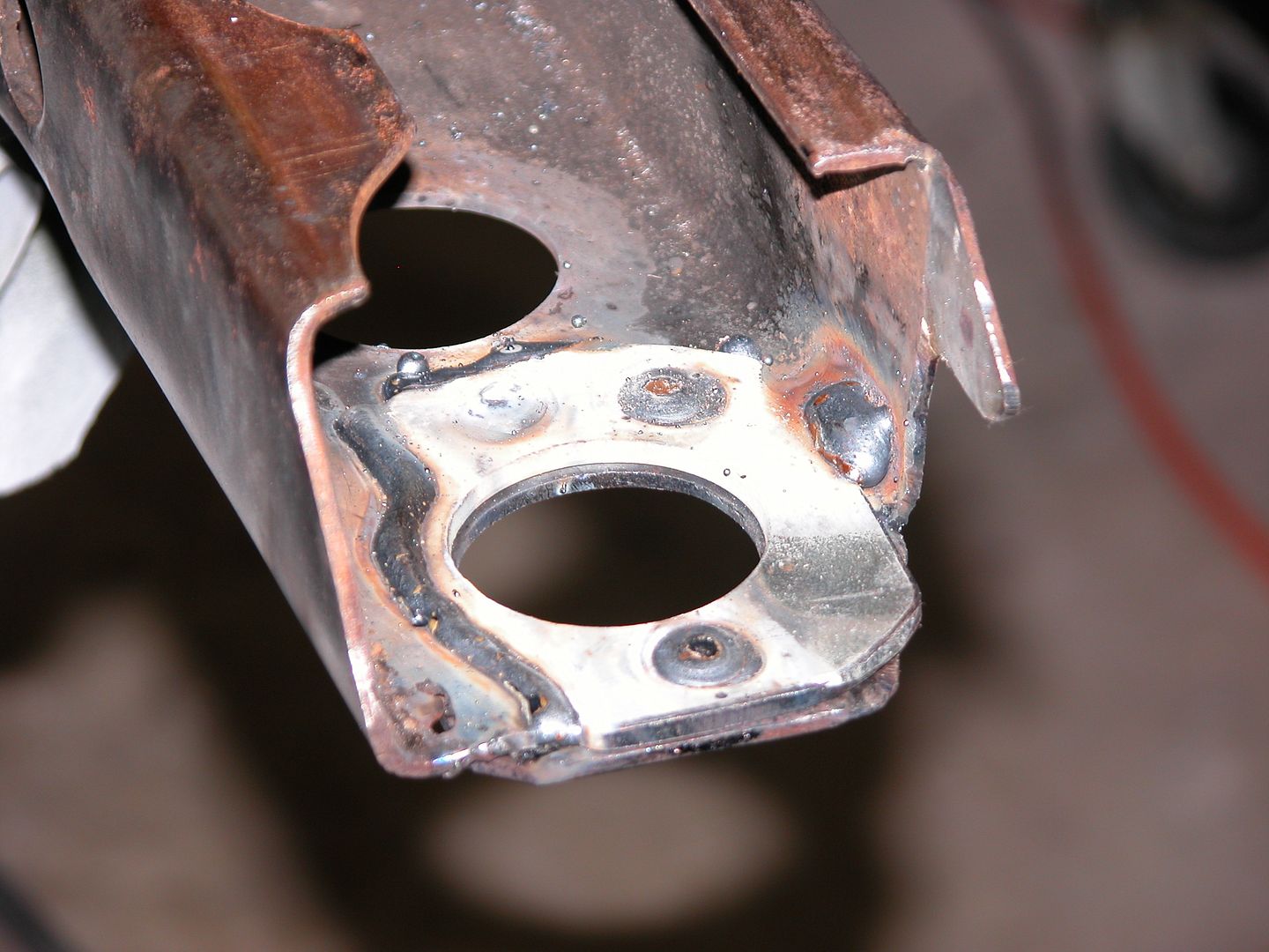 [/URL]
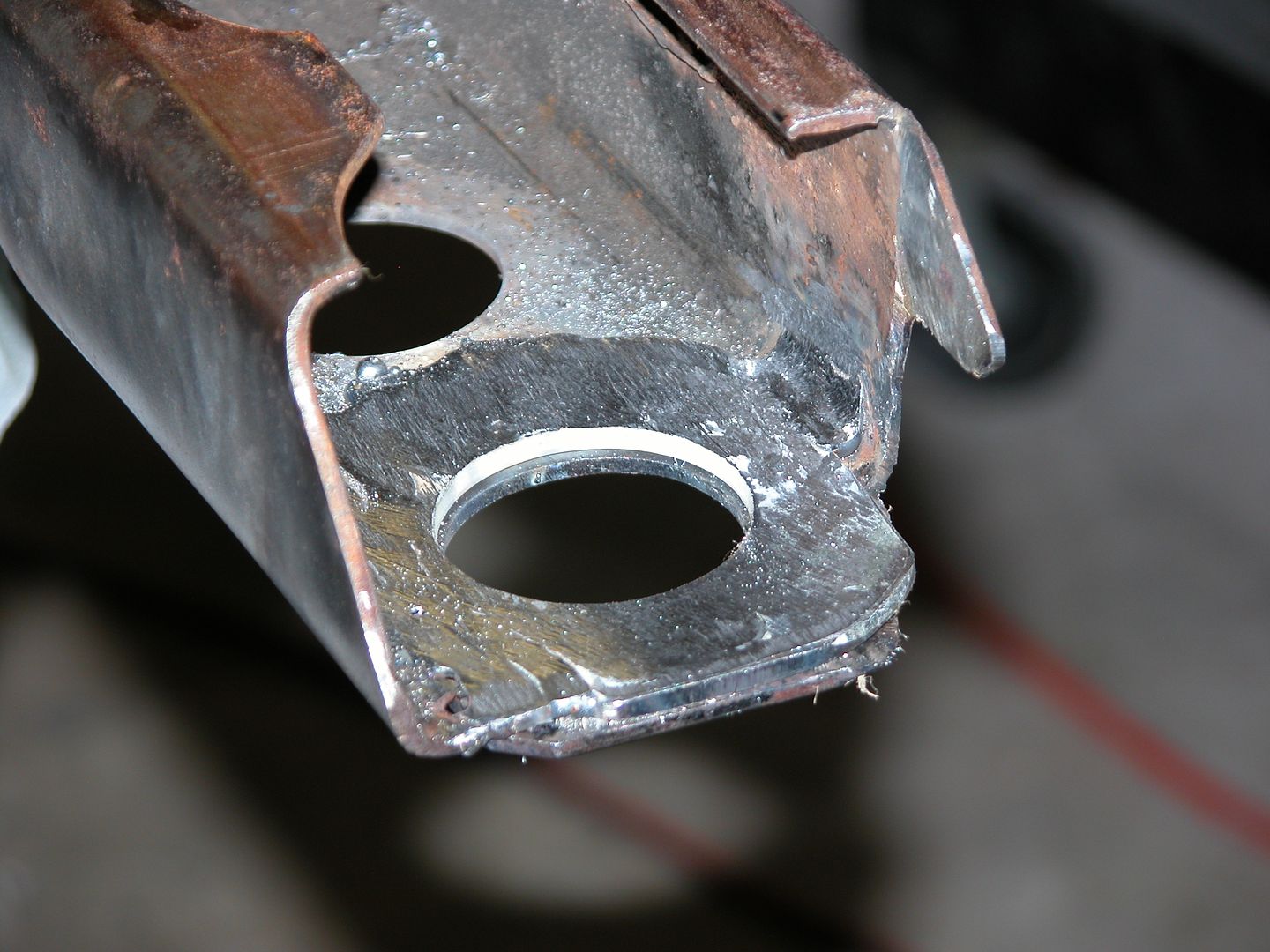 [/URL]
 [/URL]
 [/URL]
 [/URL]
 [/URL]
 [/URL]


 [/URL]


 [/URL]
 [/URL]
 [/URL]
 [/URL]
 [/URL]
 [/URL]
 [/URL]
 [/URL]
 [/URL]
 [/URL]
 [/URL]
 [/URL]
 [/URL]
 [/URL]
 [/URL]
 [/URL]
 [/URL]
 [/URL]
 [/URL]
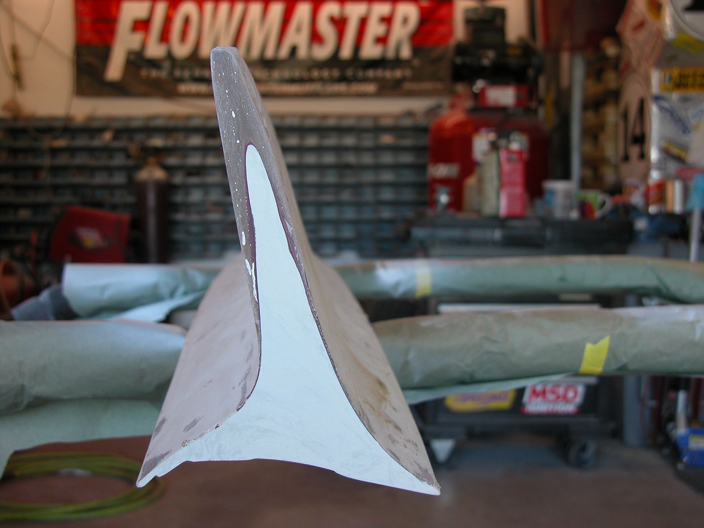 [/URL]
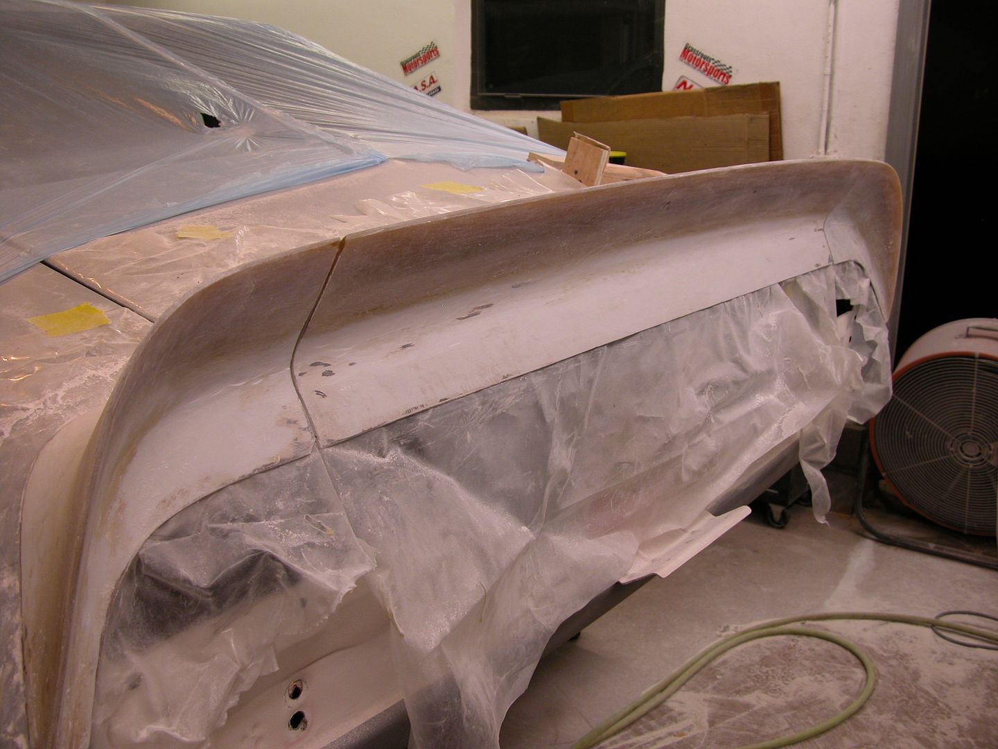 [/URL]
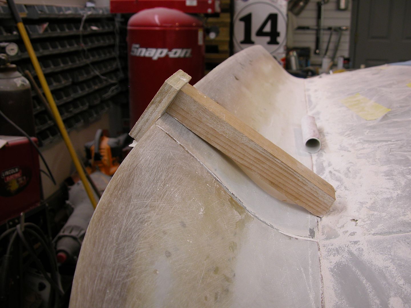 [/URL]

 [/URL]
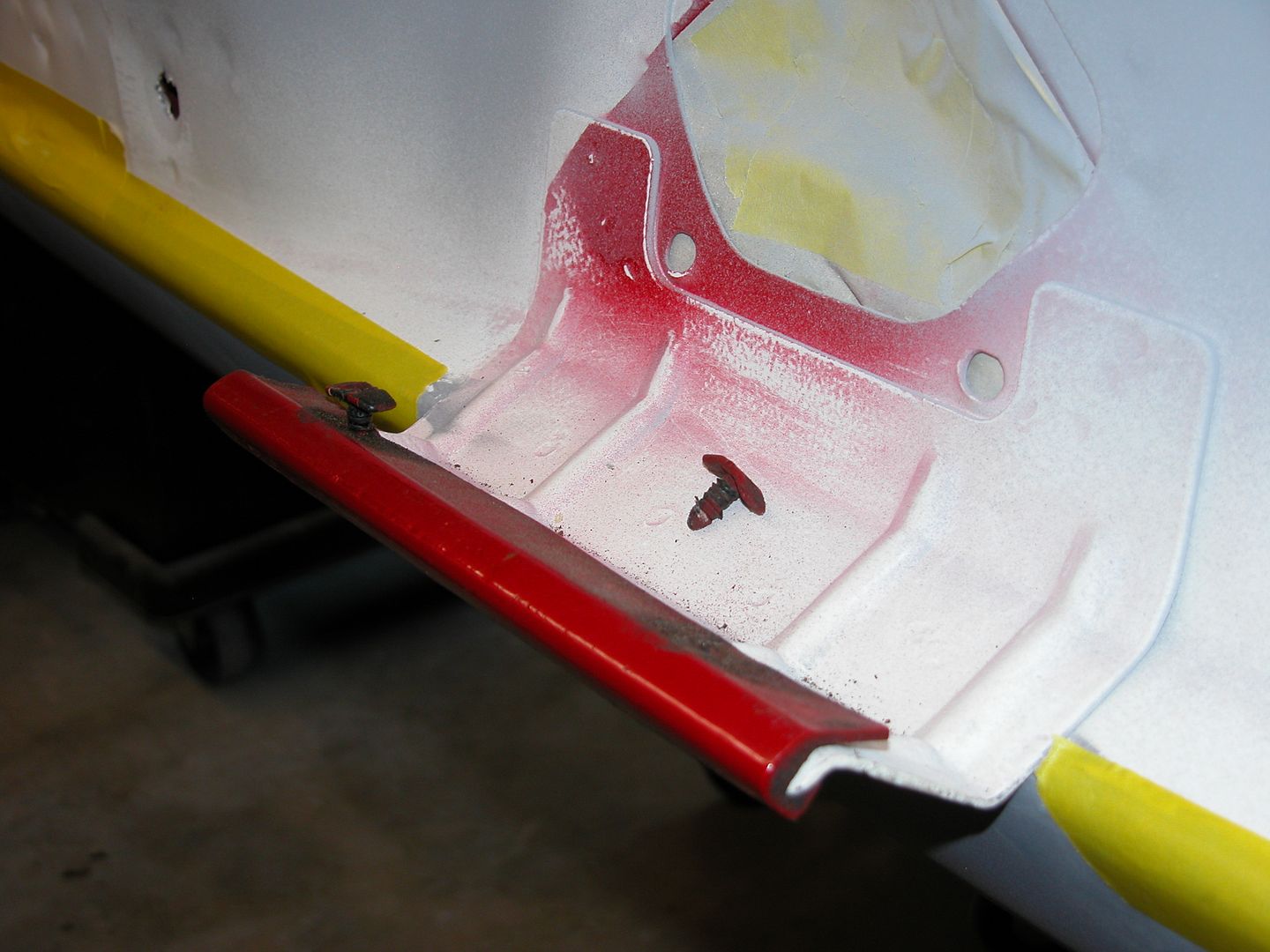 [/URL]
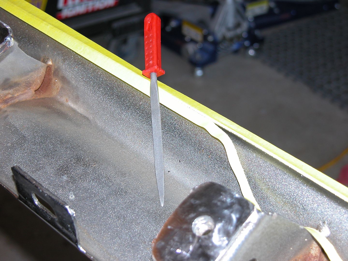 [/URL]
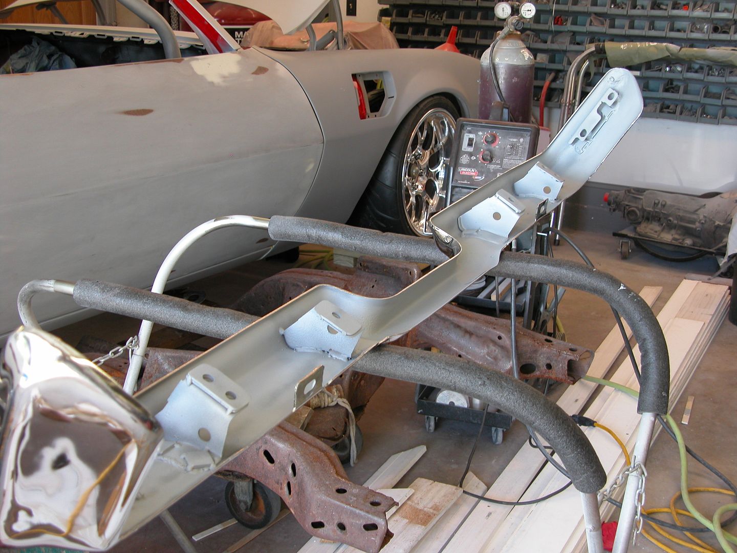 [/URL]
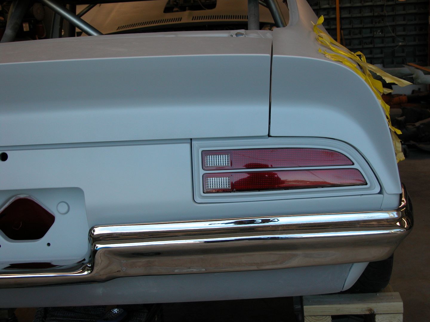 [/URL]
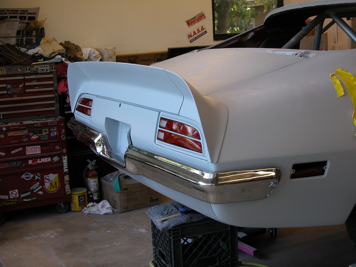 [/URL]


