


Just incredible work man....this thing is an absolute precision weapon.

Just incredible work man....this thing is an absolute precision weapon.

I remain excited every time I see this thread bumped.

Thanks guys!
Back in the fall Holley introduced a new product at the SEMA show, the Holley Hydramat. It's a product that mounts in the bottom of a fuel tank and if the fuel in the tank touches any part of the Hydramat the fuel will be sucked in even if no gas is touching the rest of the hydramat. https://www.youtube.com/watch?v=yfE1v65fNZI
Holley started shipping about a month ago so I ordered one and got it a couple weeks ago so I thought I'd show it here. Will post about it again when I get it set up in the tank. Cost of mine was a couple hundred bucks. Seems expensive but to save the same weight (on track) with lightweight parts would cost more
This looked like a good product for me to try in my stock unbaffled gas tank until I can install a properly mounted and protected fuel cell. It'll allow me to save weight by keeping less fuel in the car on road courses without risking sucking air in high G corners, reduce the pendulum effect of fuel sloshing in the tank, be safer if there's a fire because less fuel in the car, and since it's also a filter I eliminate the canister fuel filter I've been using also saving weight.
I got the magnet kit for mounting the mat in the tank and will need to install submersible fuel line instead of the stock tube and sock strainer in the tank. Holley makes other sizes and shapes of the mat as well as types of mounting setups for tanks made out of other materials.
[URL=http://s240.photobucket.com/user/NOTATA/media/The%2014%20Car%20Performance%20Therapy/004_zpslhlre45z.jpg.html]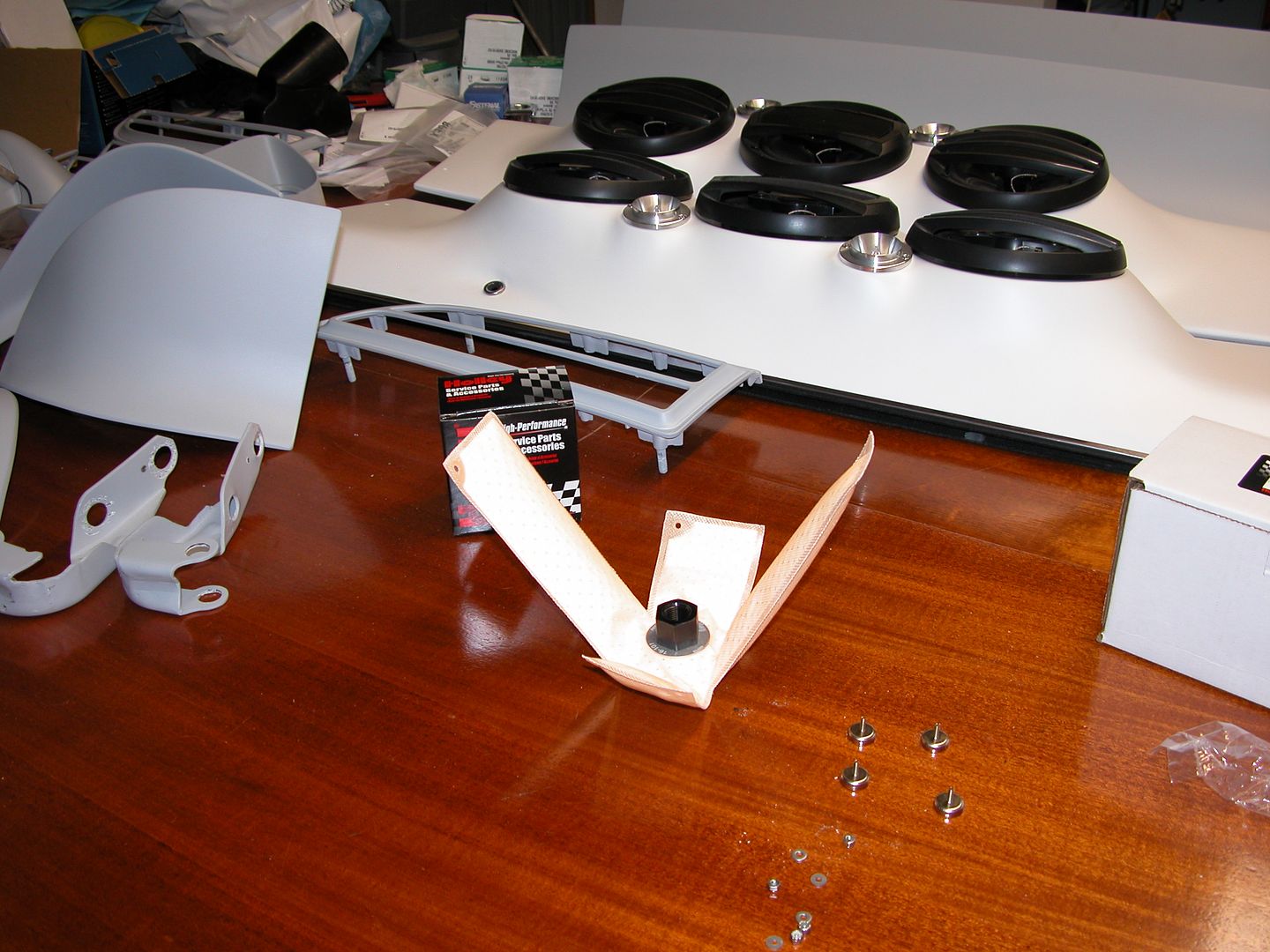 [/URL]
[URL=http://s240.photobucket.com/user/NOTATA/media/The%2014%20Car%20Performance%20Therapy/005_zpsu2wxawst.jpg.html]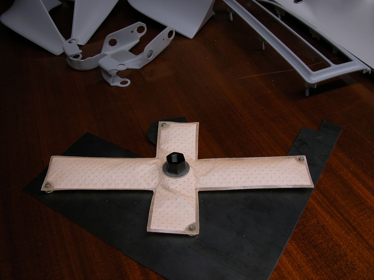 [/URL]
Back in the 70's when we ran air shocks with big and small tires on F bodies I always noticed the crappy job GM did on the pinchweld under the rear splash pan because the rear of the cars were jacked up. Well those fugly looking pinch welds are still there on most of the cars and haven't gotten any better. They got bent on ice mounds in the north, rusted, repainted without being sanded smooth or stripped, and so most look worse than they did from the factory. I'm going to make a rear diffuser for my car and folks will be looking under there taking pics etc. so I figured now's the time to even it up and make it more presentable and finished looking while getting the whole tail section in final primer.
So I gave myself a guideline and used a 4 1/2" cutoff disc to cut a thin slice off. Then ground it pretty even with a 4" grinder stone, filed it straight, and got rid of the sharp edges.
[URL=http://s240.photobucket.com/user/NOTATA/media/The%2014%20Car%20Performance%20Therapy/004_zpsualytad3.jpg.html] [/URL]
[URL=http://s240.photobucket.com/user/NOTATA/media/The%2014%20Car%20Performance%20Therapy/012_zpsjloo72dy.jpg.html] [/URL]
Is the pinch weld deleted entirely or just all 3 pieces evened up? Hard to tell in the after pic. If the flange was deleted entirely, how did you join the pieces?
Just evened up the pieces. It was hard to see while working on it too so I sprayed it white for contrast so the pinchweld lip would stand out and I could stand back and look at it to get it even with the splash pan curve.
[URL=http://s240.photobucket.com/user/NOTATA/media/The%2014%20Car%20Performance%20Therapy/005_zpsgfzdenru.jpg.html]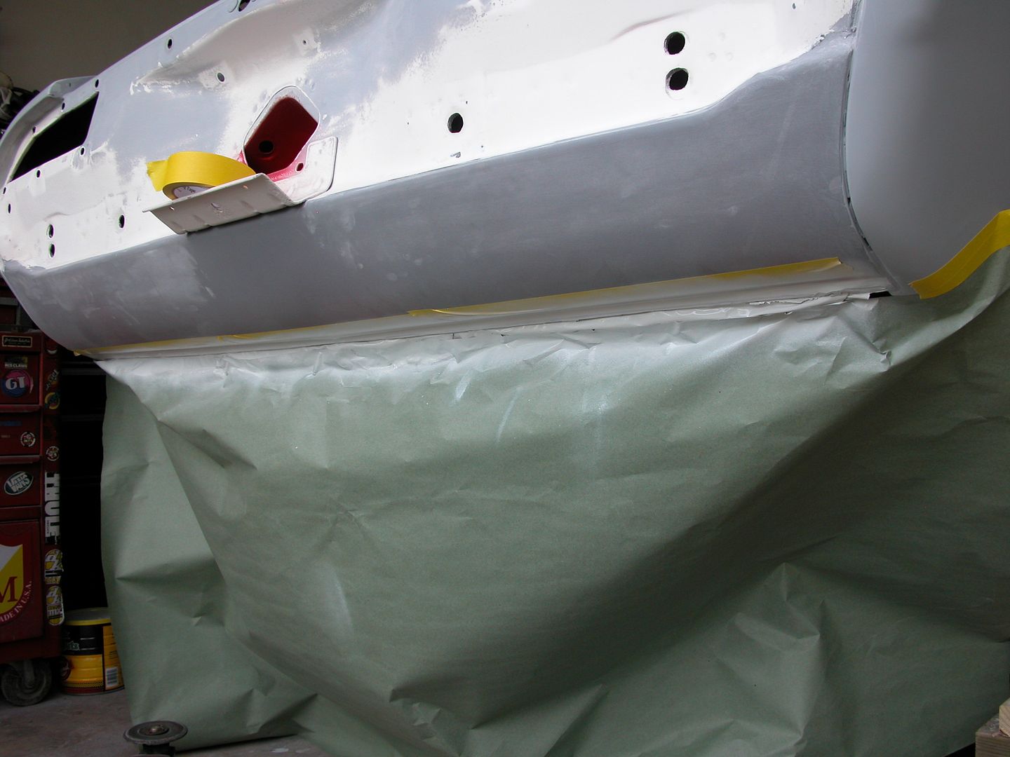 [/URL]
[URL=http://s240.photobucket.com/user/NOTATA/media/The%2014%20Car%20Performance%20Therapy/003_zps6gvppeet.jpg.html]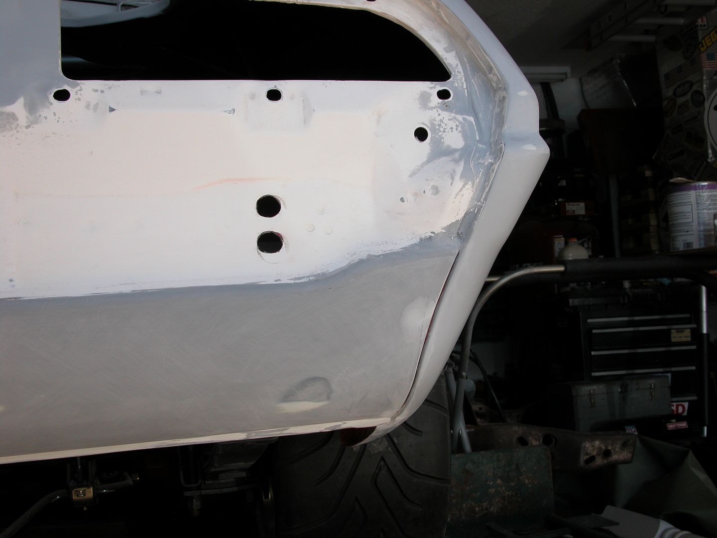 [/URL]
Very nice.
With the rear of the car in final primer I spun the car around (Go-Jacks are awesome!) and turned my attention to lining up the doors and front end sheet metal. I'd loosely assembled everything to determine if I'd be able to use the 81 subframe, 70 steering, and 70 core support with the solid body mounts. There are differences in the subframe front horns that affect the position of the bumper brackets and steering but with various modifications it looks like I should be able to get everything to fit.
The door hinges were installed bare metal to bare metal at the factory on the 2nd gen F body cars I've worked on. If the area where the hinge mounts is covered in primers/paint it's a lot more difficult to line up the doors because the paint sticks together when the bolts are snugged or tightened. Then if you try to move a hinge just a little while aligning things it usually jumps farther than you want it to move once you get it to pop free.
So I sand down the area on the cowl and door as well as the hinge surfaces to make adjustments easier. Then because I'll be leaving the hinges on the cowl when the doors come off for the cut ins I sanded down the final primer that was already there to 320 for paint because it's easier to sand without the hinges in the way (they'll also get the Scotchbrite scuff before paint).
Once sanded, a little spray lithium grease gets shot inside where the plate slides around in the cowl and door and a thin film of grease where the hinge touches the cowl and door. This allows easier adjustment of the doors and a bit of corrosion protection. Careful attention to keep grease off areas that will be painted is a must and after the hinges are mounted wax and grease remover used all around hinges to remove any possible residue.
[URL=http://s240.photobucket.com/user/NOTATA/media/The%2014%20Car%20Performance%20Therapy/004_zpspg0mywq2.jpg.html]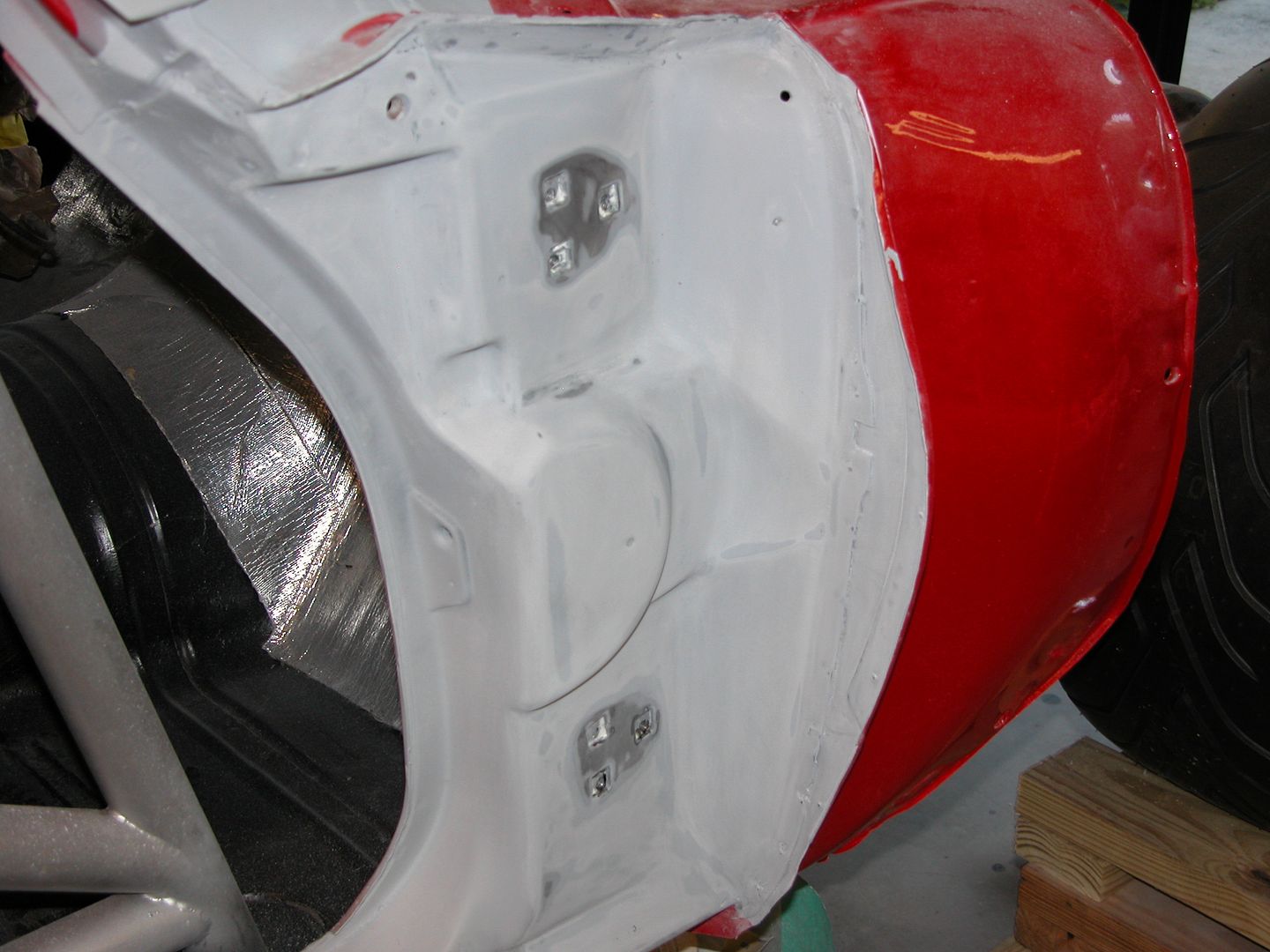 [/URL]
[URL=http://s240.photobucket.com/user/NOTATA/media/The%2014%20Car%20Performance%20Therapy/003_zpsurzs3agw.jpg.html]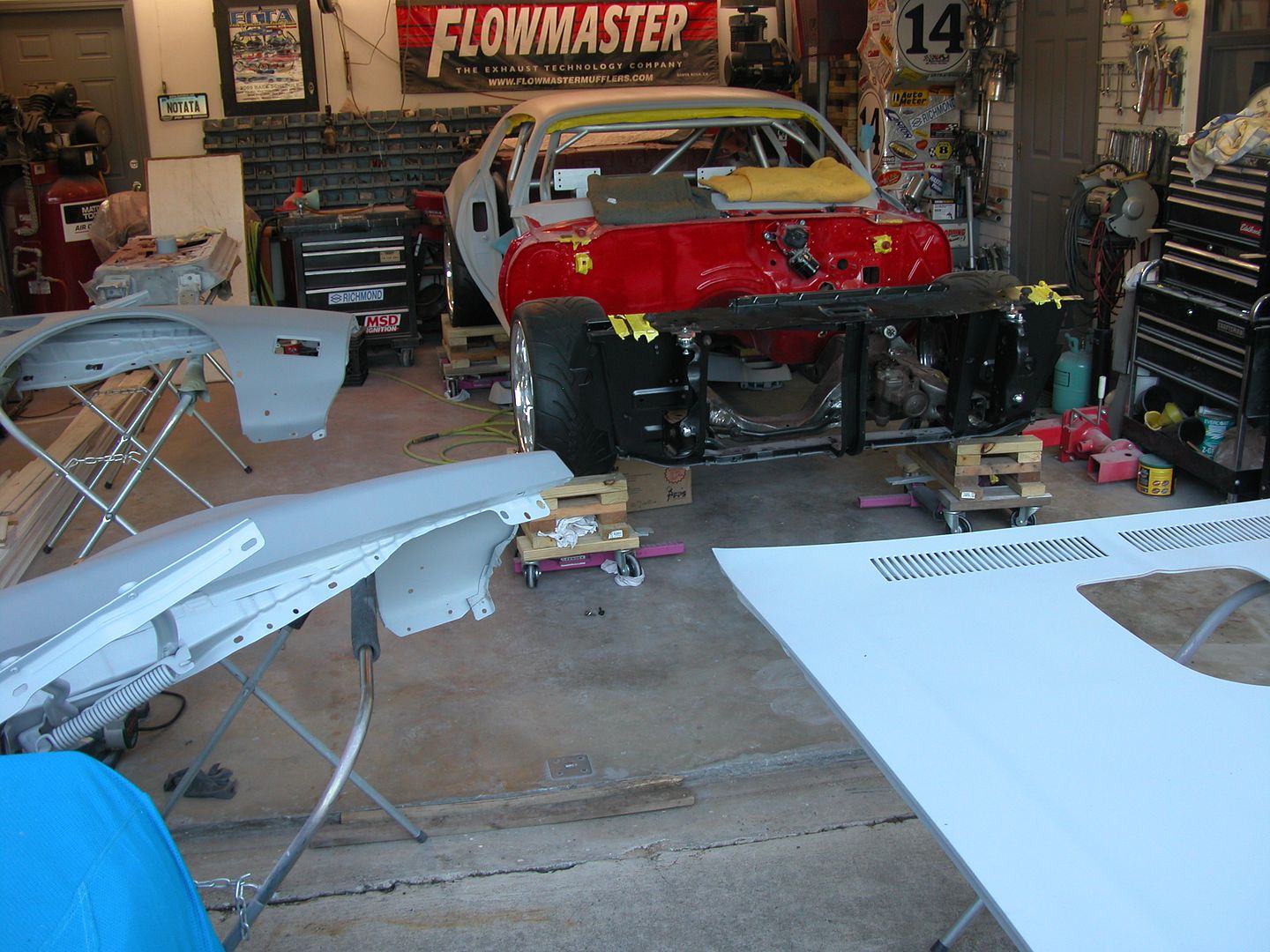 [/URL]
I'm currently working on front end assembly/panel alignment and some fender vent aero mods I'll talk about in my next progress post. However I've been wanting to post about this problem unique to 70-73 bird's for years and today's the day!
Soapbox time! 70-73 Firebird front bumper and panel alignment.
I was a car guy teen when these cars were new and been researching/studying the bumper mounting , panel fitment, and the gaps for the past 25-30 years since my stepson got his first 70. Most of the 70-73 front ends on birds I see now have not been assembled/aligned correctly. THE FRONT BUMPER IS NOT SUPPOSED TO TOUCH THE FENDERS.
There is supposed to be a gap. It's wider than people want to see. Nobody likes it, not even the folks at Pontiac liked it when they were new. As you can see in the pics below the marketing people at Pontiac photoshopped (was that a thing then?) the gap between the fender and bumper right out of some of the pics in the 70 brochure because it looks "funny".
I see many beautiful cars where the owners have taken every step they can, buying NOS and correct original pieces for crazy prices just so they know they've got the right stamping's, date codes, etc. only to see the whole front end isn't panel aligned correctly. I feel bad for them because they just don't know. To me it's almost like hearing someone say they've got a "Big Block" Pontiac.
Soon after these cars were built they started getting in accidents etc.requiring bodywork and paint. IF the person took it back to the dealer the shop might have put the bumper back on correctly however many shops might just try to eliminate or reduce the gap if they even knew there was supposed to be a gap. It's been over 45 years since these cars were built and so even a body man who was in his 20's is probably retired even if he was a body man his whole life. So the folks who've been repainting these cars the past 30 years or so probably never even saw these cars new and don't realize the bumper isn't supposed to touch the fender. Most in the restoration/ body repair business now never saw these cars before they started being reassembled wrong so they try to split the differences and make the panel alignment/gaps look as good as they can with the bumper tight to the fender because they never even saw one with the correct gap. The misconception has gone on so long now that the majority of the cars I see now are assembled wrong and look kinda wonky but few realize why. The poor panel alignment is often attributed to the lower quality sheet metal stamping of yesteryear.
The subframe, bumper brackets, and bumper (as a solidly bolted structure) were isolated from the unibody,fenders, core support, splash pan, and core support/latch brackets (again solidly bolted structure) by 8 rubber bushings allowing the 2 sections to move slightly independent of each other. 4 rubber body mounts, 2 rubber core support mounts, and the 2 rubber upper bumper mounts. This allowed movement of the two structures individually and so a gap was needed between the fenders and bumper to prevent the bumper being deformed on uneven surfaces and when the car was jacked up. When the first urethane bumpers arrived on the 69's they put a rubber gasket between the bumper and body and people didn't like it so in 70 they reduced the gap and left it open.
The gap needs to be roughly 3/16" - 1/4" on most of the cars to get everything lined up as well as can be keeping in mind that factory stamping and tolerances of early 70's cars was nothing like today's cars.
In this first page from the brochure you can see that the marketing guys made the gap disappear on the passenger side of the upper image while it is clearly seen on the lower image.
[URL=http://s240.photobucket.com/user/NOTATA/media/CCF11062013_0000_zps53db5f97.jpg.html]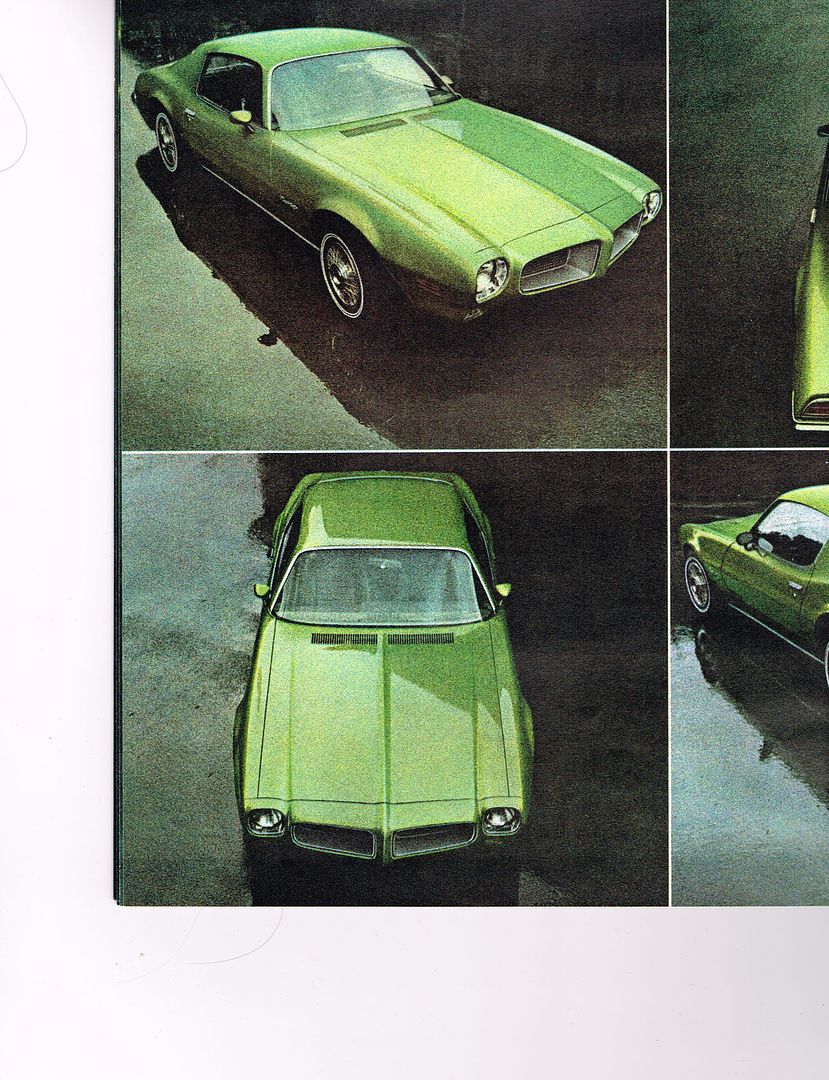 [/URL]
On the page below you can clearly see the gap, note the front of the hood lines up with the front of the fender.
[URL=http://s240.photobucket.com/user/NOTATA/media/CCF11062013_0001_zps200f0ca5.jpg.html]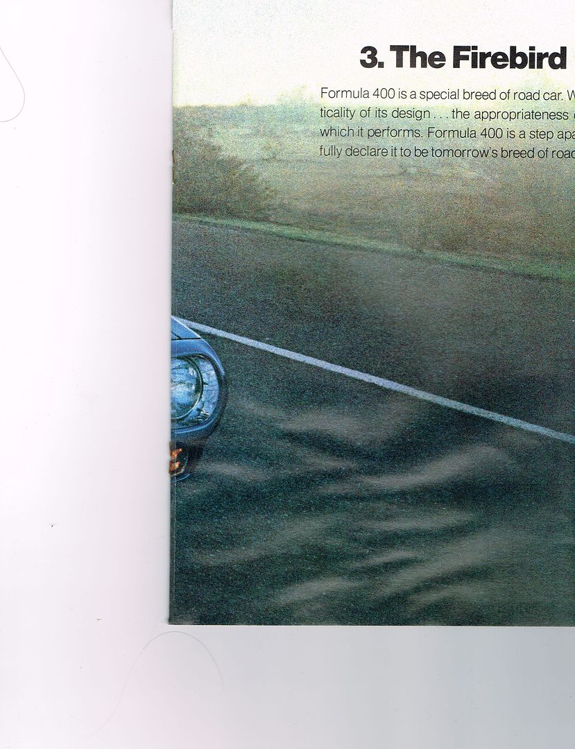 [/URL]
Apparently the marketing folks figured the gap showed up waaay too much on a white car.
[URL=http://s240.photobucket.com/user/NOTATA/media/CCF11062013_0002_zpsd6233dc1.jpg.html] [/URL]
Pic below is exaggerated to show how the body lines and fitment get screwed up. Think of it as taking a slice out of a cone and then trying to mate the remaining pieces. The gap needs to be roughly 3/16" - 1/4" on most of the cars to get everything lined up as well as can be keeping in mind that factory stamping and tolerances of early 70's cars was nothing like today's cars. When folks try to have the bumper touch the fender it causes problems aligning the front end sheet metal. Several problems arise and folks try to juggle all the pieces to minimize the affects but the pieces won't line up well so the common thought is "They just didn't make the cars very good back then"
These are the most noticeable effects of trying to have the bumper touch the fender.
The hood sticking too far back toward the windshield and sticking up even when the hinges are adjusted to the max trying to lower it.
The middle of the hood arches above the fender. Commonly attributed to the "Formy arch" or lousy hood springs. It's actually also caused by the hood being too far back and the arch of the hood not matching the arch of the fender.
When the bumper is tight to the fender people pull the fenders in toward the hood trying to get the points on the top of the bumper to line up with the top of the fender. this causes too small of a gap to the hood and often the car gets assembled without the side rubber hood bumpers because they push the hood up causing the mid hood arch to be off even more with the fender.
When the fenders are pulled in, the bottoms of the fender get pulled in afterward when trying to get the side of the fender to curve like the side of the bumper. Then the splash pan seems like it's too long.
The side body line will be off because when pulling the bumper tight to the fender it also gets raised to have the top of the bumper flush with the top of the fender. So the bumper body line ends up slightly higher than the fender body line. Sometimes this gets "fixed" during bodywork with filling/blocking if the bumper is on the car at the time.
[URL=http://s240.photobucket.com/user/NOTATA/media/The%2014%20Car%20Performance%20Therapy/CCF06182015_0000_zpsqlvmwxjp.jpg.html]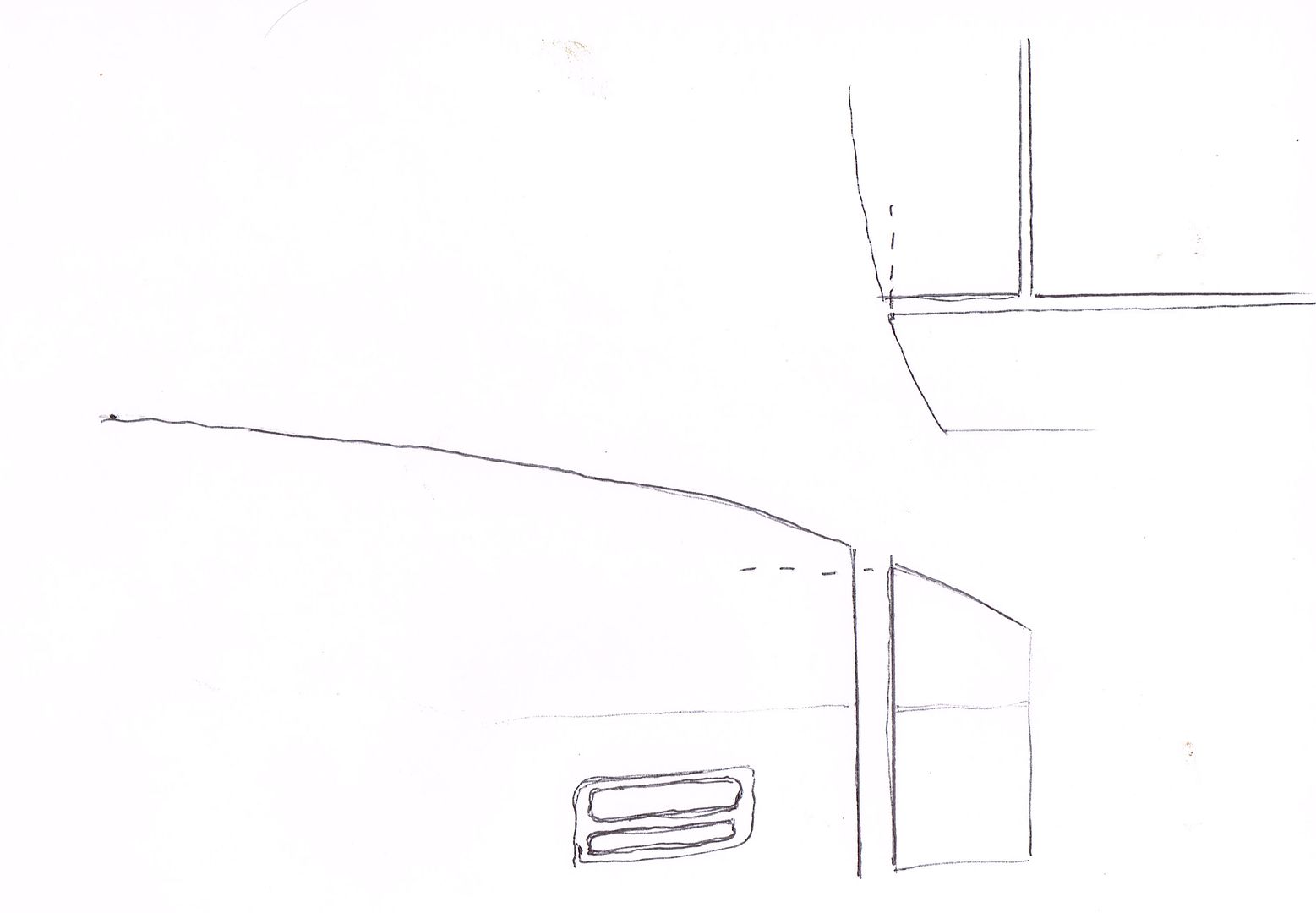 [/URL]
The crude sketches below show how the car is built. The main portion of the car is comprised of the unibody along with all the front sheet metal bolted solidly together (excluding hood because it's on hinges). It includes the fenders, inner fenders, inner fender extensions, core support, latch support, and splash pan. The smaller section includes the subframe, bumper brackets, and bumper (with lights and grills) bolted solidly together with the front suspension and steering attached. A third section is the engine/transmission bolted solidly together and "floating" on rubber mounts over the subframe.
The gap was necessary to allow the two main sections of the car to move a little independent of each other without damaging the sides of the bumper and paint on the leading edge of the fenders.. Even if you use solid body mounts the bumper still needs the gap to get the panel alignment correct because it was designed knowing the gap was necessary and the body lines needed to appear to flow over the gap.
[URL=http://s240.photobucket.com/user/NOTATA/media/The%2014%20Car%20Performance%20Therapy/CCF08252015_0000_zpsd1uncyu6.jpg.html]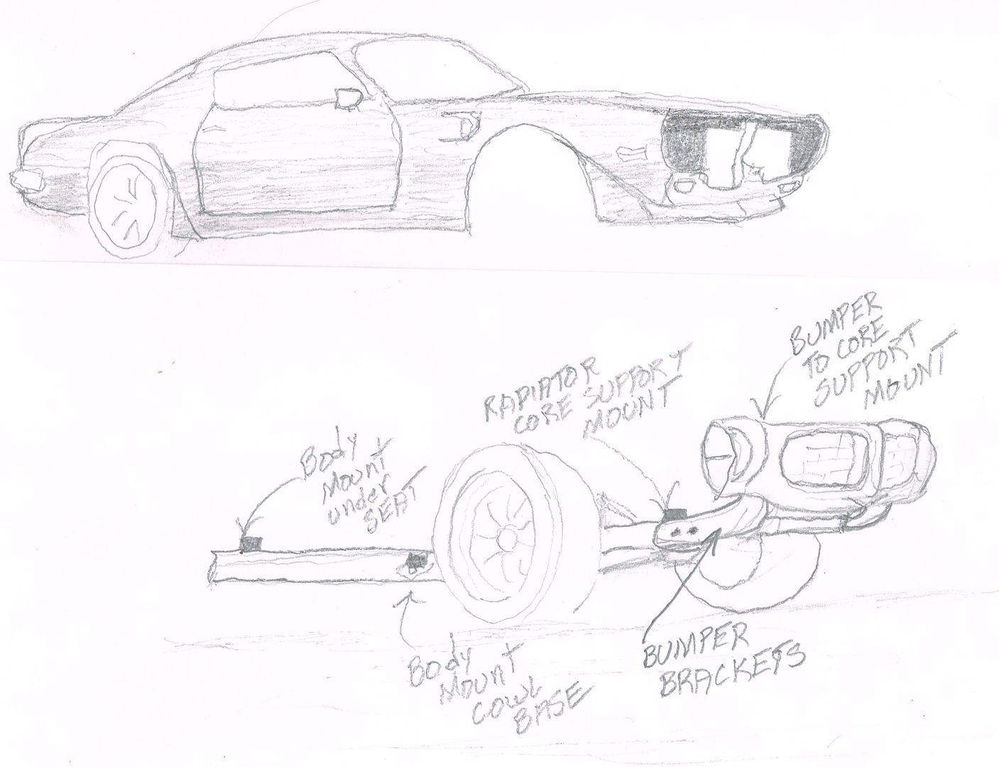 [/URL]
Came across some pics on another forum that demonstrate how NOT to line up the bumper. This is a classic example of what happens when folks try to have the bumper touch the fender and don't know what they're doing is wrong. As an added bonus it also shows how the more flexible formy hood reacts. Don't worry, I'm not picking on someone's car that's being used like this. It's already apart for restoration.
The bumper below looks like it was installed while the car was on jack stands or a lift and they tried to have the bumper touch the fender. Then when they dropped the car on the ground the result was popping the paint on the drivers side of the bumper and a funny gap on the passengers. The hood was moved back so there would be a gap and the hood corners by the windshield probably got sanded off because they looked funny. The fenders were pulled in toward the hood in front trying to match the bumper causing the raised section of the Formy hood mid fender. Also notice the side body line of the bumper is now too high compared to the fender.
[URL=http://s240.photobucket.com/user/NOTATA/media/0321151820_zps2yhvzsnk.jpg.html] [/URL]
[URL=http://s240.photobucket.com/user/NOTATA/media/0321151817_zpsruxsxa1e.jpg.html] [/URL]

well, I will never need to know that most likely but it was entertaining to read!
Thanks for the lesson!

That is interesting stuff. I don't have an F body but I've been fooling around with Pontiacs for over 40 years (I have a '61 Bonneville), and I've heard many stories about the difficulties in lining up the front clip on the cars of that era.
I knew that post wasn't really anything anyone here would probably have a direct need to know but I wrote it for the thread which is being followed by a lot of folks on the Trans Am forums where it is also being posted.
Funny thing is even though there's LOTS of 70-73 Firebird and TA owners following the thread on those forums there hasn't been even one response to it on any of them! It's like I told them their mom was an Amy and they are in disbelief. I wrote it because the front end of almost all of the 70-73 cars I see on those forums are all goofy looking because the bumper isn't installed the way it was designed to be. When they take pics of their cars they try to find angles that don't make it so noticeable that the panel alignment is off when they post them.

Fascinating. I like knowledge. Also, I really appreciate this thread.
wheelsmithy wrote: Fascinating. I like knowledge. Also, I really appreciate this thread.
Glad you like the thread! Now on to something more entertaining than a bumper gap.
One of the aero changes I wanted to make involves the fender vents. I'm planning on a splitter and pan under the engine compartment. So I need to evacuate the under hood air that comes through the radiator and reduce high pressure air under the hood that causes lift. Many have experienced the effect called "float" at high speeds (over normal highway speed) in regular cars and some models are worse than others. The 2nd gen TA fender vents help reduce that and I want to maximize the benefit.
So I began by doing some tuft testing on the stock vent with the screen removed to see how it performed. Then I made cardboard modifications to the vents and tested again. I spent more than a day on this process testing various configurations and came up with a couple modified vents that should help keep the air pressure lower under the hood. For a more detailed version of the testing and how the modified vents were made see this thread which just covers my aero mods. http://transamcountry.com/community/index.php?topic=71522.0
The stock TA vent has a hole with surface area about 15 sq. in. The screen in the stock vent blocks off about 5 sq.in. reducing it to 10 sq. in. and creates turbulence as the air tries to exit through it. As I went through the testing process I changed the angle of the leading edge, added wicker bills of varying heights and expanded the opening. The modified vents now have openings about 3 times the sq. in. with steeper leading edge and the design of the housings seem to draw a lot more air from under hood. One set will be used for Land Speed racing type events (less drag) and the one with the wicker at the leading edge will be for road course use (more drag but also more evacuation).
As I mentioned it was a long process and lots of variations were tuft tested. Here's a few pics to show a couple of the differences.
Stock vent with screen removed.
[URL=http://s240.photobucket.com/user/NOTATA/media/The%2014%20Car%20Performance%20Therapy/006_zpsth3q9sas.jpg.html]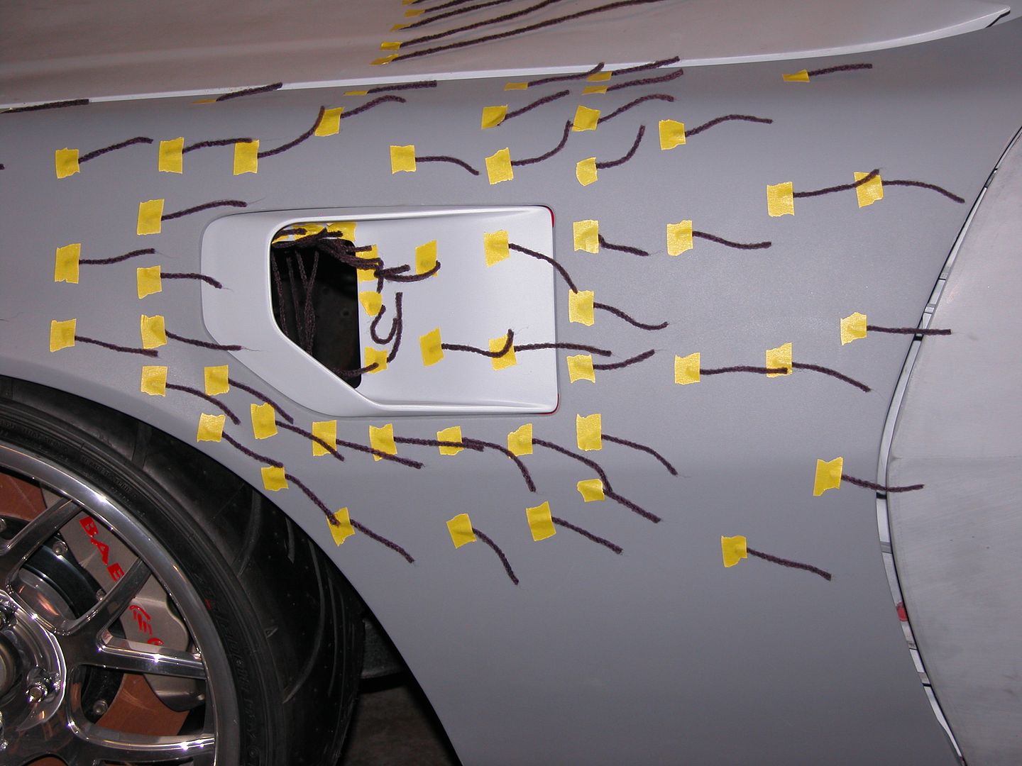 [/URL]
Modified vent below with steeper leading angle and stock opening.
[URL=http://s240.photobucket.com/user/NOTATA/media/The%2014%20Car%20Performance%20Therapy/005_zps9hux3vb5.jpg.html]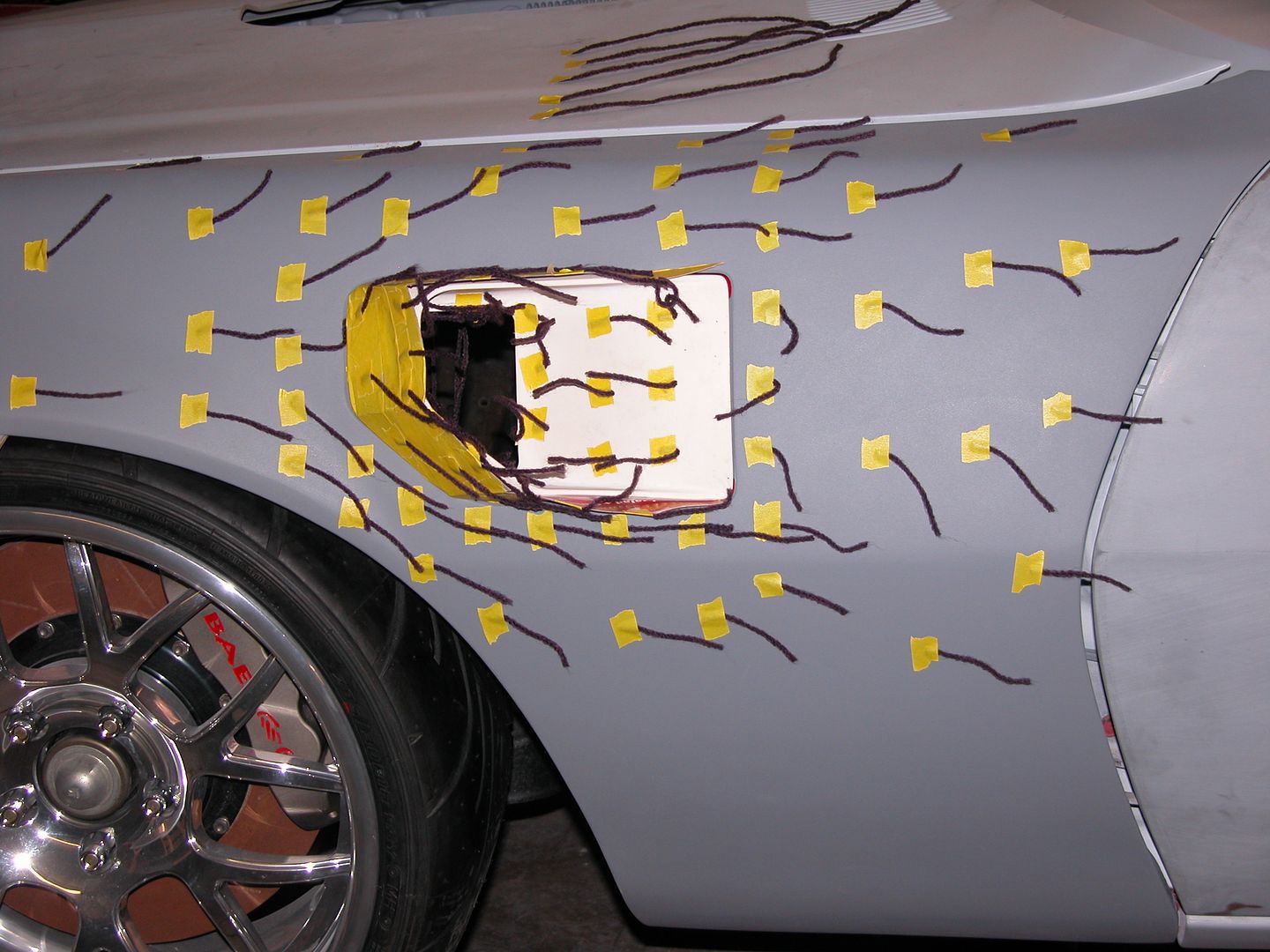 [/URL]
Modified vent with wicker and extra slot opening below.
[URL=http://s240.photobucket.com/user/NOTATA/media/The%2014%20Car%20Performance%20Therapy/010_zpsviry1faw.jpg.html]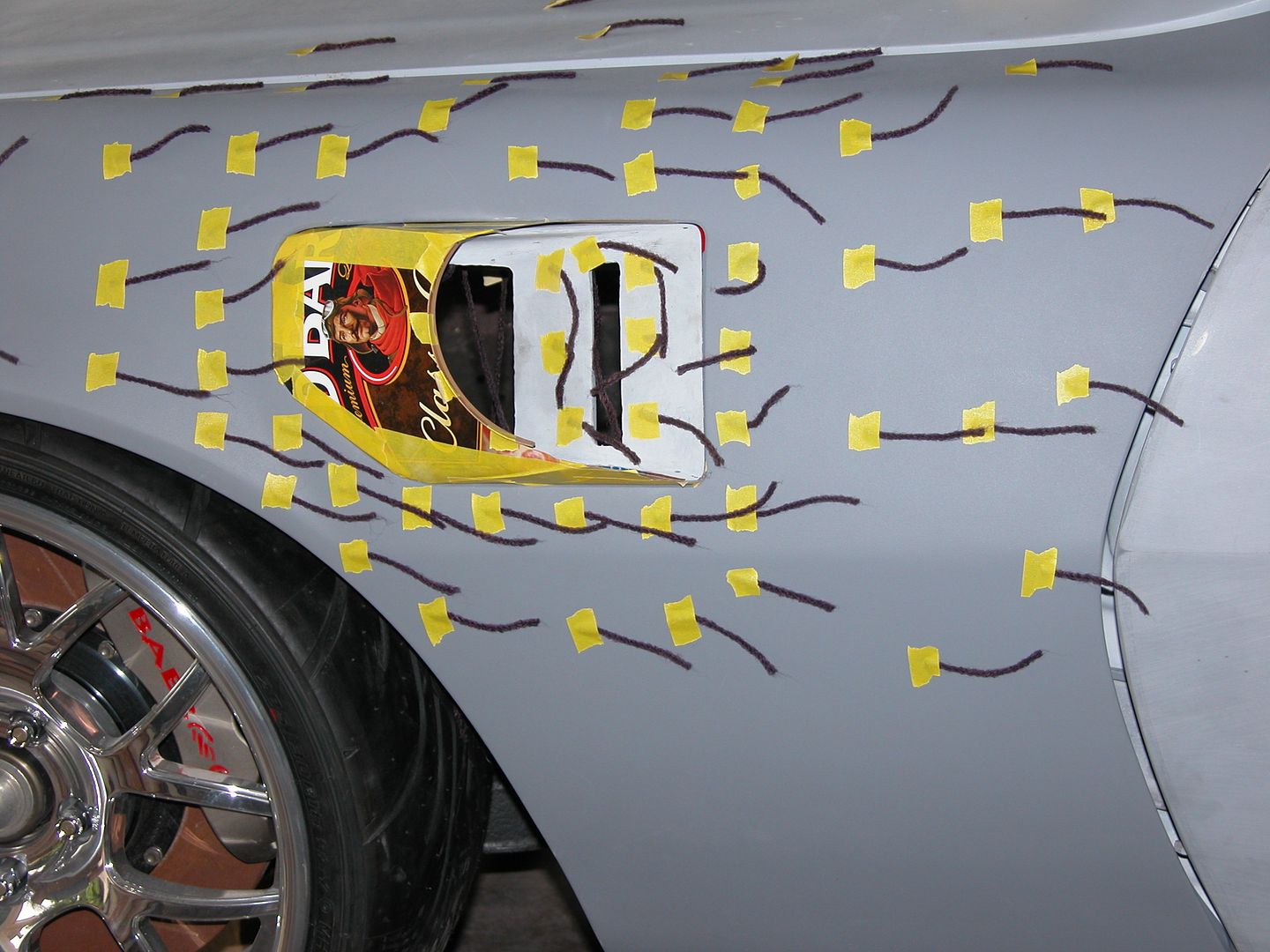 [/URL]
This version seemed to get the best results for evacuation with reduced turbulence. But it wasn't enough "better" to warrant all the extra effort I'd have to put in to incorporate strakes into my design.
[URL=http://s240.photobucket.com/user/NOTATA/media/The%2014%20Car%20Performance%20Therapy/016_zps4etgb5xy.jpg.html]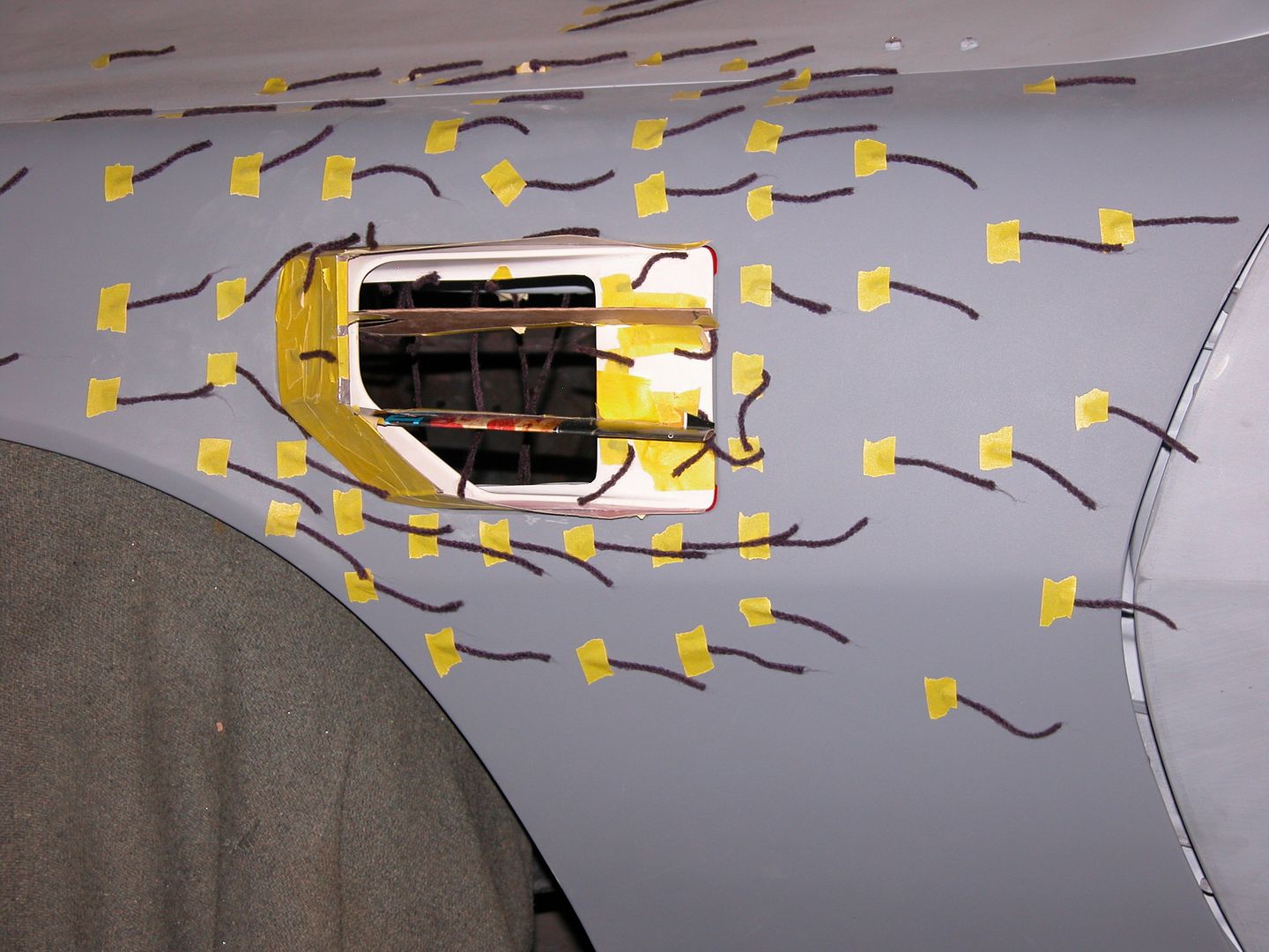 [/URL]
Here are the designs I came up with and made. Will tuft test in the real world once the car is back on track. Top pic below is process. Then stock vent, LSR vent, and track vent.
[URL=http://s240.photobucket.com/user/NOTATA/media/The%2014%20Car%20Performance%20Therapy/Barefoot%20and%20Track%20Jack%20vents%20002_zpslz3vt75a.jpg.html] [/URL]
[URL=http://s240.photobucket.com/user/NOTATA/media/The%2014%20Car%20Performance%20Therapy/011_zps6u07qwkc.jpg.html]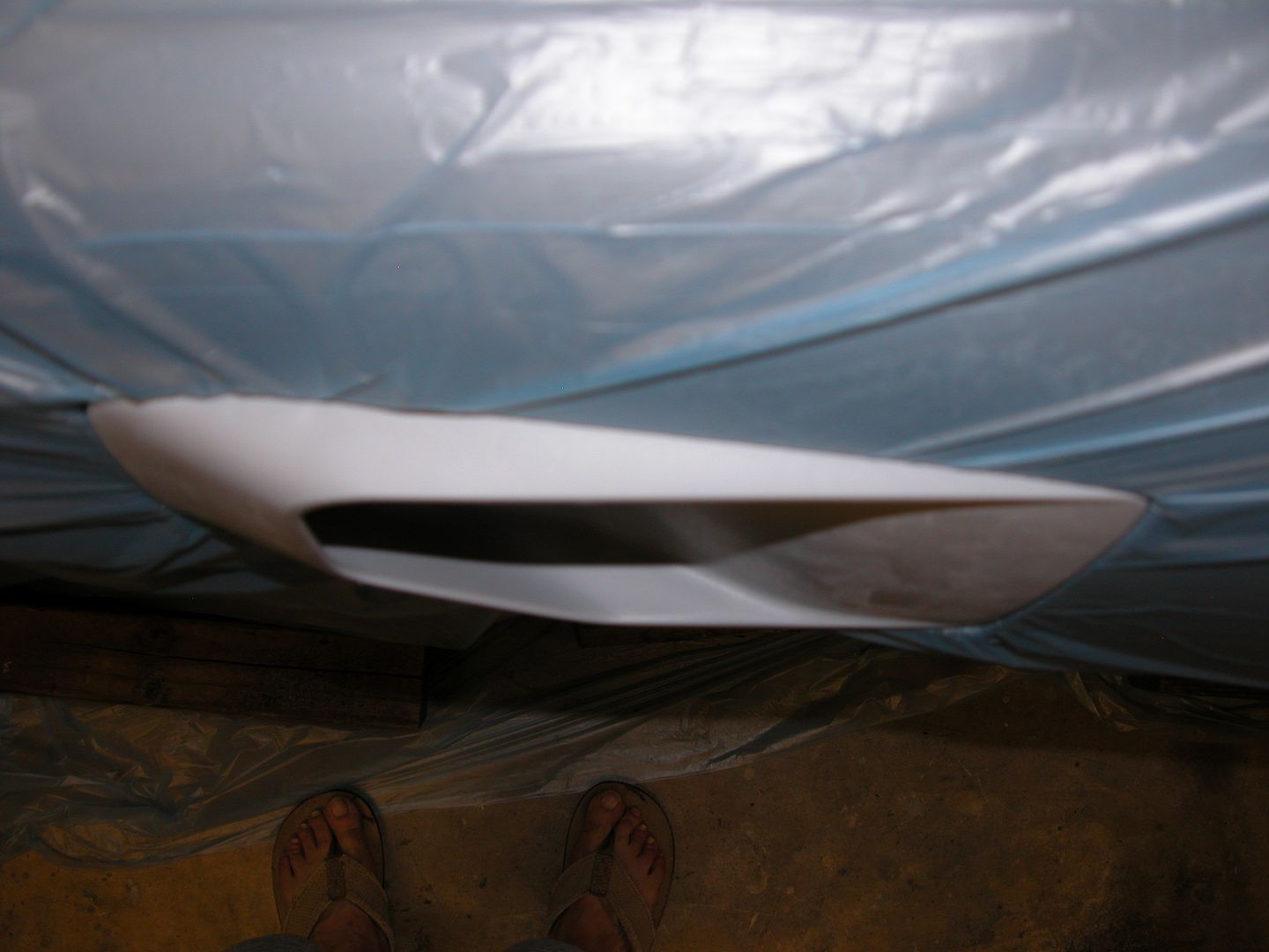 [/URL]
[URL=http://s240.photobucket.com/user/NOTATA/media/The%2014%20Car%20Performance%20Therapy/013_zpst24ch5dm.jpg.html] [/URL]
[URL=http://s240.photobucket.com/user/NOTATA/media/The%2014%20Car%20Performance%20Therapy/012_zpsrh4zmoby.jpg.html]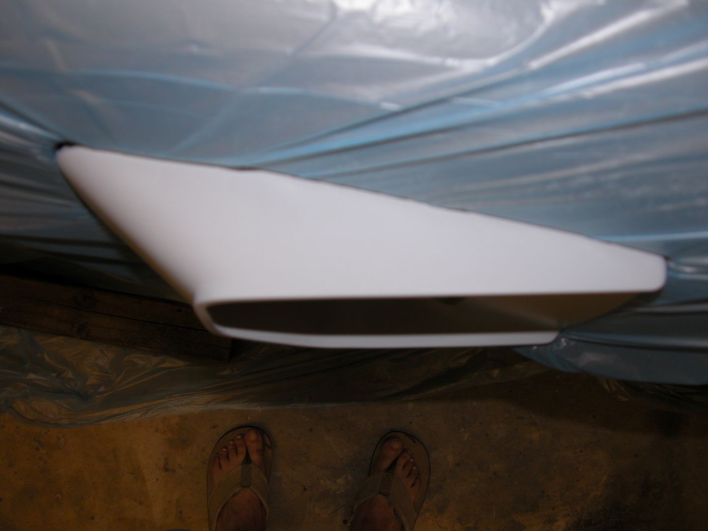 [/URL]
[URL=http://s240.photobucket.com/user/NOTATA/media/The%2014%20Car%20Performance%20Therapy/018_zpsywajddeh.jpg.html]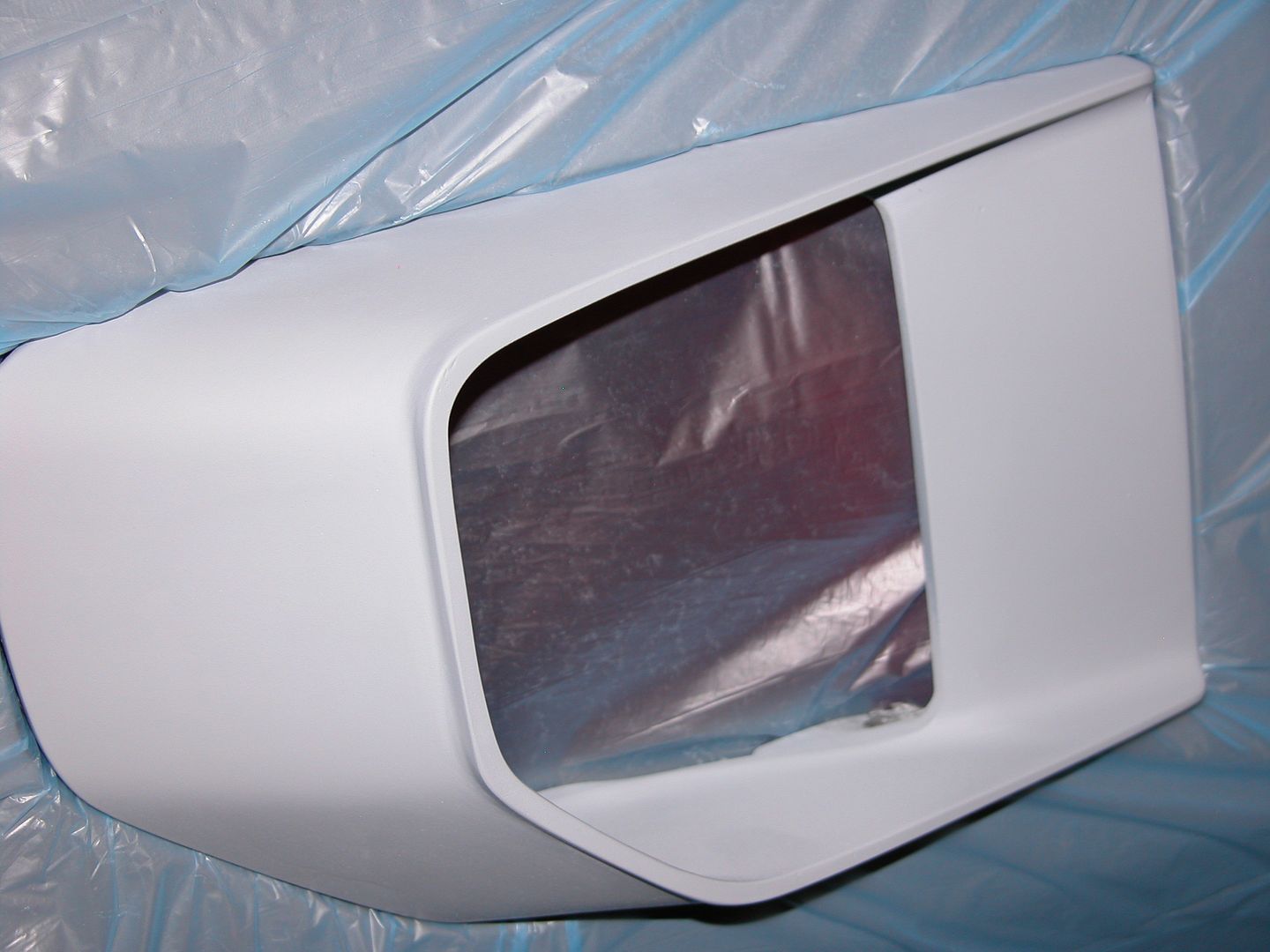 [/URL]
[URL=http://s240.photobucket.com/user/NOTATA/media/The%2014%20Car%20Performance%20Therapy/016_zpskcm6k7wu.jpg.html]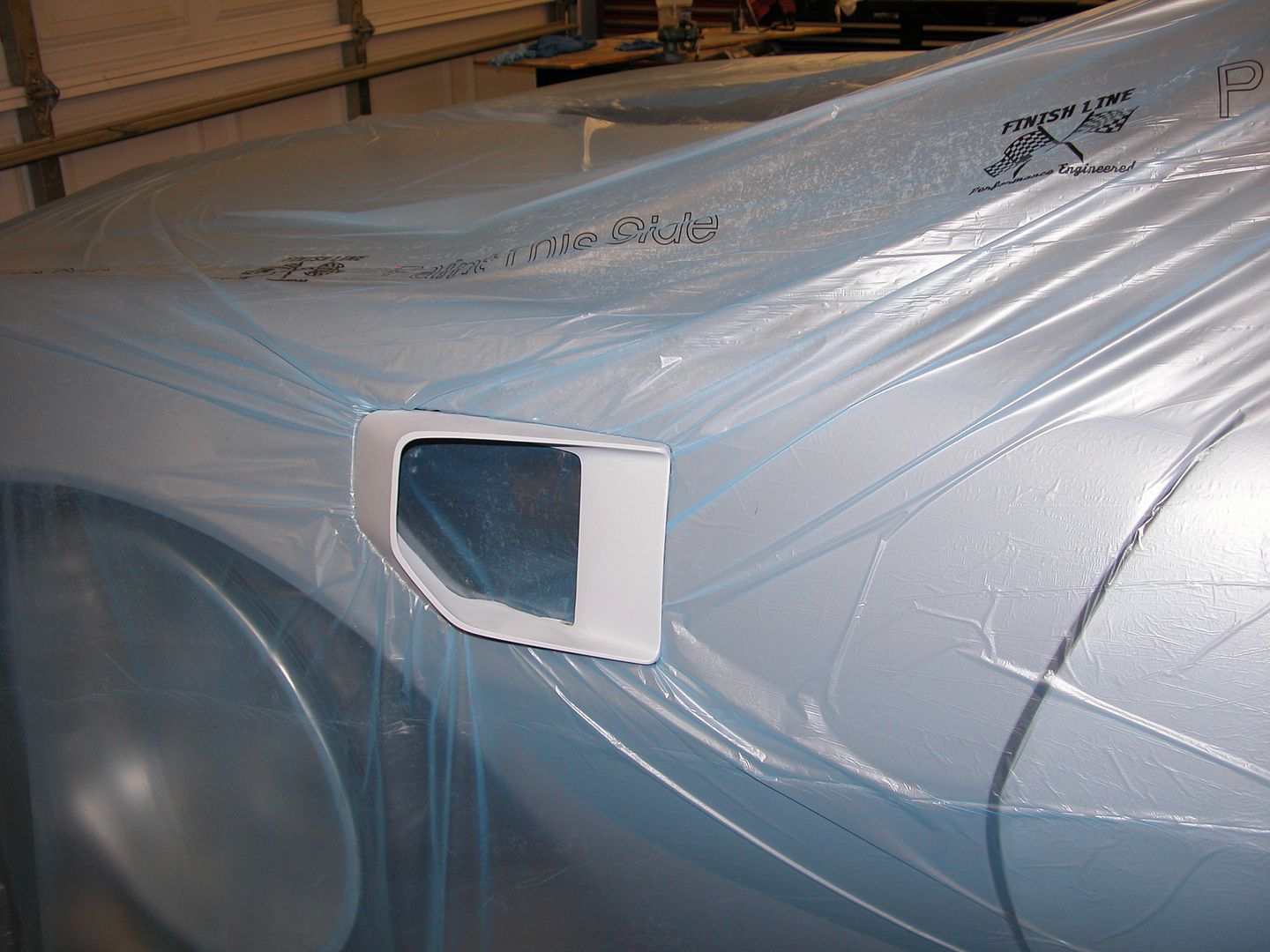 [/URL]

That is excellent work.
Thanks Nick!
Moving along with aerodynamic modifications I'm currently working on the front end treatment.
The splitter/tray/air dam combination I've got in mind is a bit unusual from those I've seen on other cars.
A. Hinged to allow the splitter to be pushed up if I hit corner curbing or something. Splitter could rise till it hits the stock air dam. I've never whacked the stock air dam and I'll probably only loose maybe 1/2" ground clearance.
B. Two piece splitter/tray so I can have various splitters that stick out more or less with the biggest reaching out as far as the leading edge of the bumper and out as wide as the wickers on the wheel flares.
C. Height adjustable so I can use for street, LSR, Drag strip, road course, or open road with various height air dam extensions.
D. Various air dam extensions that will fold up if the splitter gets pushed up. Probably three versions, small for drag race & street , medium for road tracks, and a deep air dam extension with minimal ground clearance for LSR with no splitter but supported from behind by the tray section.
E. Breakaway provisions so if something bad happens, damage to the car would be minimal and hopefully confined to the splash pan and stock air dam/wheel flares.
F. Cheap/replaceable using as many pieces of scraps left from other projects and junk people gave me as I can. I gathered all the stuff I've been collecting and figured I could make something out of it even if just a prototype. It'll get the scraps out of my way and hopefully save me a few bucks.
While today lots of folks use CAD I still use DIG (Draw In Garage) for projects like this. Here's the basic concept drawing. The tray section the various splitters will be attached to has a smaller footprint than the stock air dam/wheel flare section.

[URL=http://s240.photobucket.com/user/NOTATA/media/The%2014%20Car%20Performance%20Therapy/010_zpsxpirxxyt.jpg.html]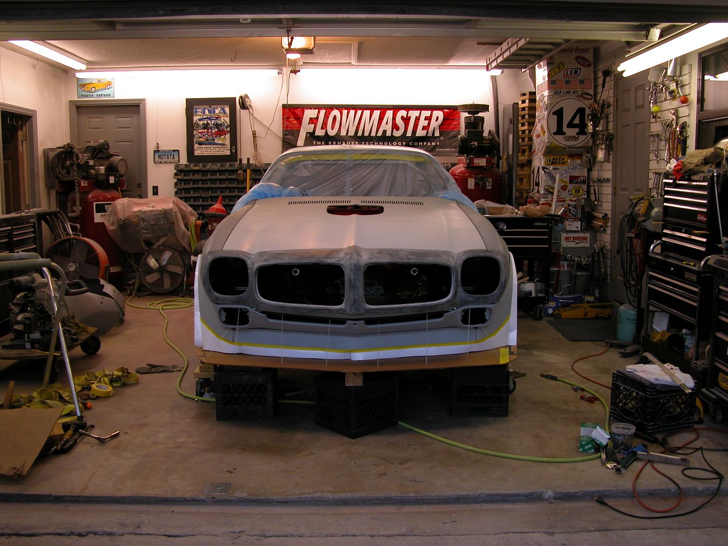 [/URL]
I have a buddy who did a similar splitter that would fold up. Rather than the standard struts that are usually used to locate it, he used aircraft cable. Plenty strong to deal with downforce, doesn't restrict upward movement.
DILYSI Dave wrote: I have a buddy who did a similar splitter that would fold up. Rather than the standard struts that are usually used to locate it, he used aircraft cable. Plenty strong to deal with downforce, doesn't restrict upward movement.
I guess that's kind of along the same lines as what I'm doing. Do you know where I could find any pics of what he did? Maybe he's got a better mousetrap? Here's where I'm at in pic below. I'll post more about it when I finish final assembly of it. Hardboard and PVC uprights in pics are just for mock up.
[URL=http://s240.photobucket.com/user/NOTATA/media/The%2014%20Car%20Performance%20Therapy/013_zpsqonzbgbm.jpg.html]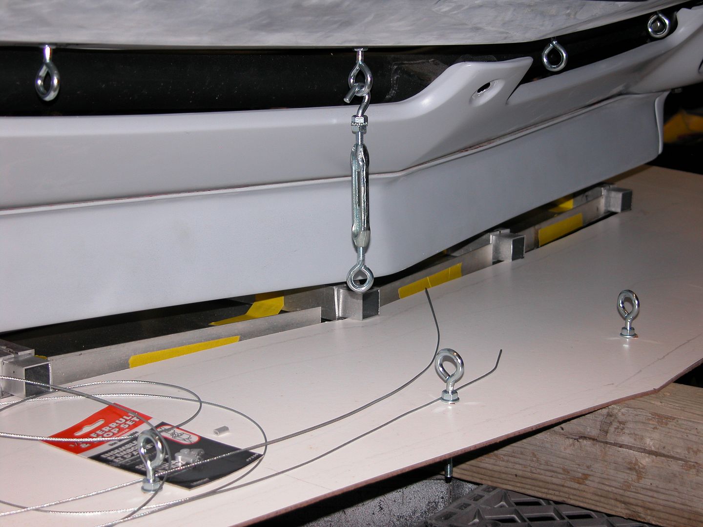 [/URL]
[URL=http://s240.photobucket.com/user/NOTATA/media/The%2014%20Car%20Performance%20Therapy/010_zpsvl8r0t1d.jpg.html]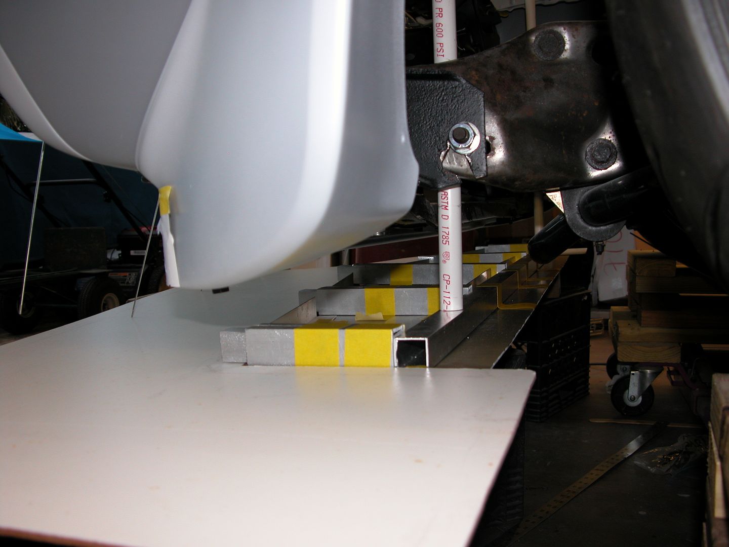 [/URL]
I've gotten ahead of my progress posts so I've got to catch up. Below are pics of the splitter/air dam combinations I'll be testing. Not sure if there'll be any issues with using cable supports which might allow the splitter to oscillate or bounce. If there are issues I'll install solid splitter supports.
The contraption in it's current configuration adds about 27 lbs to the nose of the car. This includes a lot of hardware weight I'll eliminate if it works as planned. The splitter easily supports my full wieght with just 2 of the cables in place. The hinging ability works and so in theory might save me from wrecking it. Front sections of various lengths can be slid into place in just a couple minutes. I started making plastic pieces to mate the original air dam and wheel flares with the splitter and will finish them when I determine the exact heights I'll try the splitter at once the car is assembled and on the ground with full weight. 3/8" plywood is being used for testing the front sections and I may use a different material later if everything functions as I'd like once road tested.
[URL=http://s240.photobucket.com/user/NOTATA/media/The%2014%20Car%20Performance%20Therapy/001_zpsirxstnu6.jpg.html]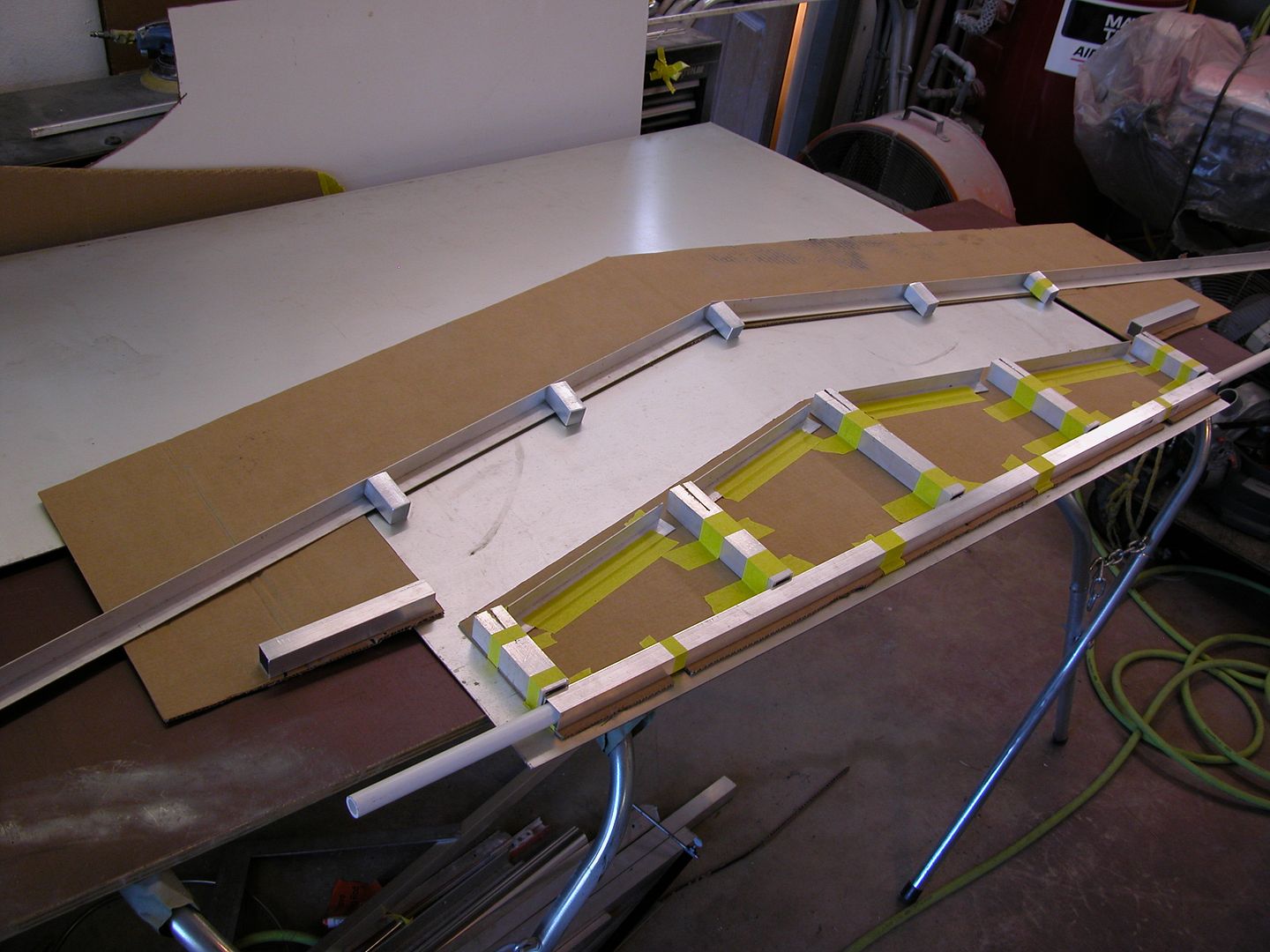 [/URL]
[URL=http://s240.photobucket.com/user/NOTATA/media/The%2014%20Car%20Performance%20Therapy/008_zpsgsc65mzj.jpg.html]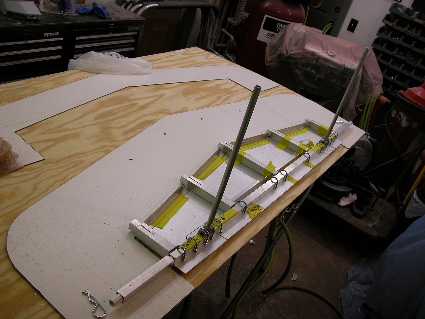 [/URL]
[URL=http://s240.photobucket.com/user/NOTATA/media/The%2014%20Car%20Performance%20Therapy/004_zpsksroqlgy.jpg.html]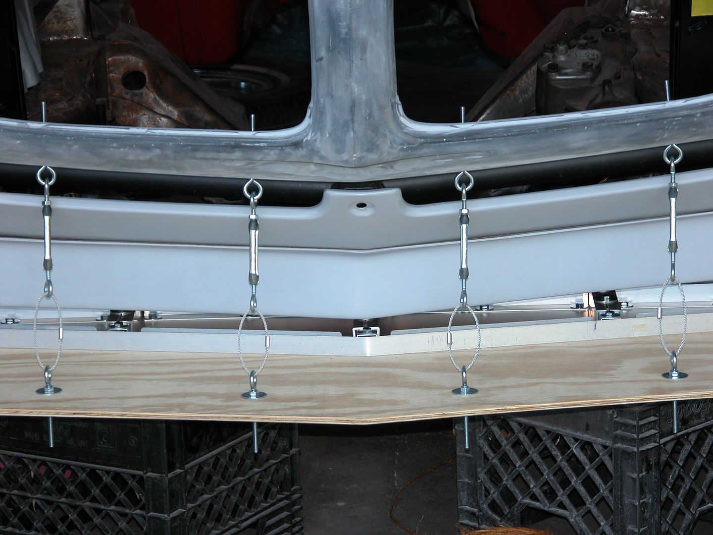 [/URL]
[URL=http://s240.photobucket.com/user/NOTATA/media/The%2014%20Car%20Performance%20Therapy/007_zps91ms5mvr.jpg.html]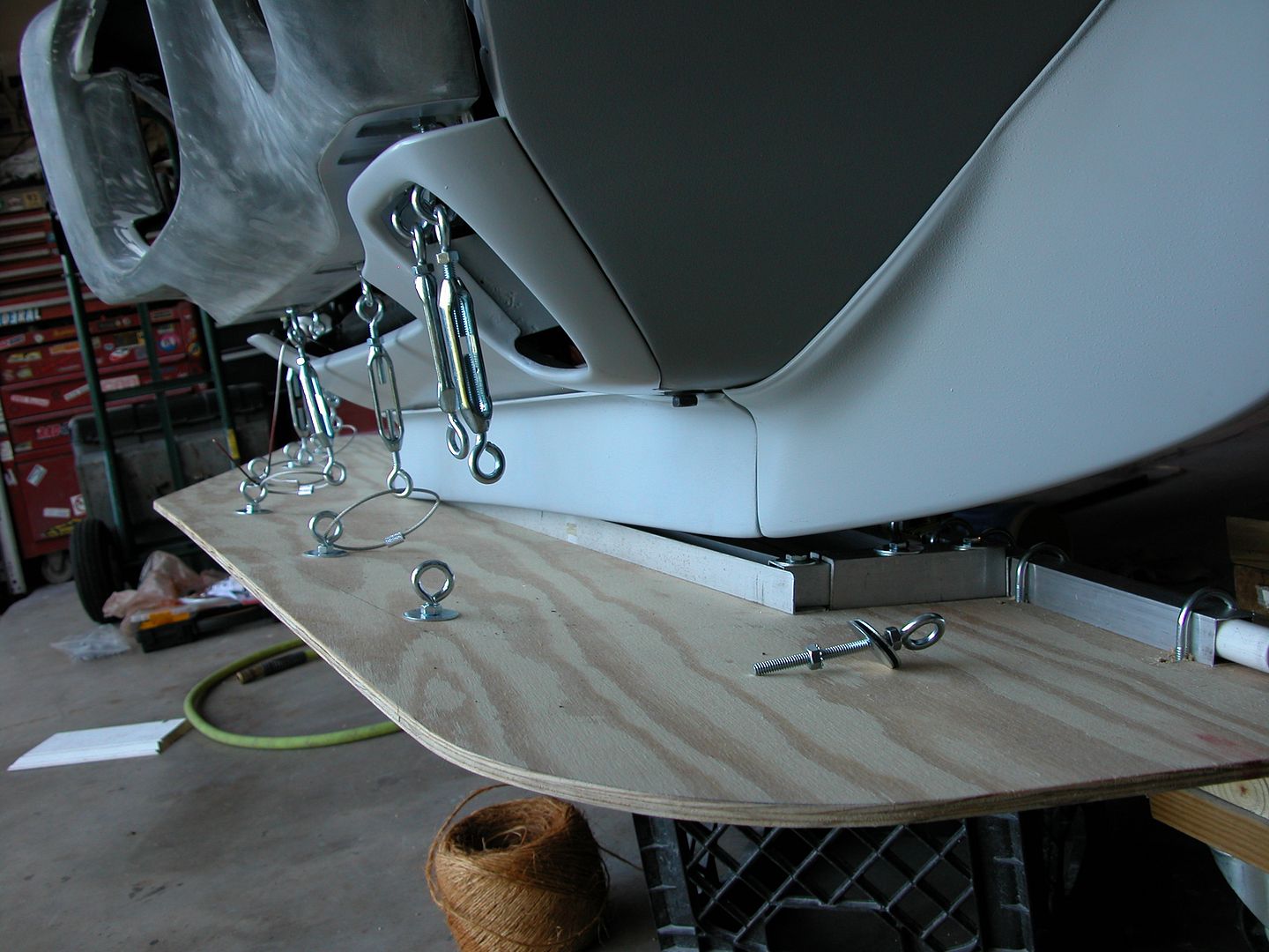 [/URL]
[URL=http://s240.photobucket.com/user/NOTATA/media/The%2014%20Car%20Performance%20Therapy/002_zpsxyfgvtln.jpg.html]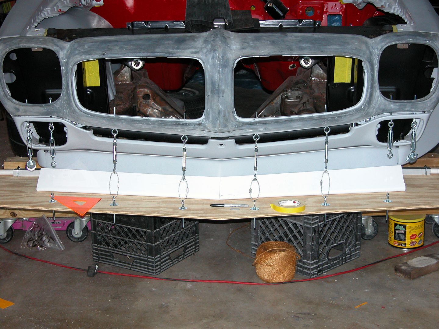 [/URL]
[URL=http://s240.photobucket.com/user/NOTATA/media/The%2014%20Car%20Performance%20Therapy/004_zpsnqctt6dr.jpg.html]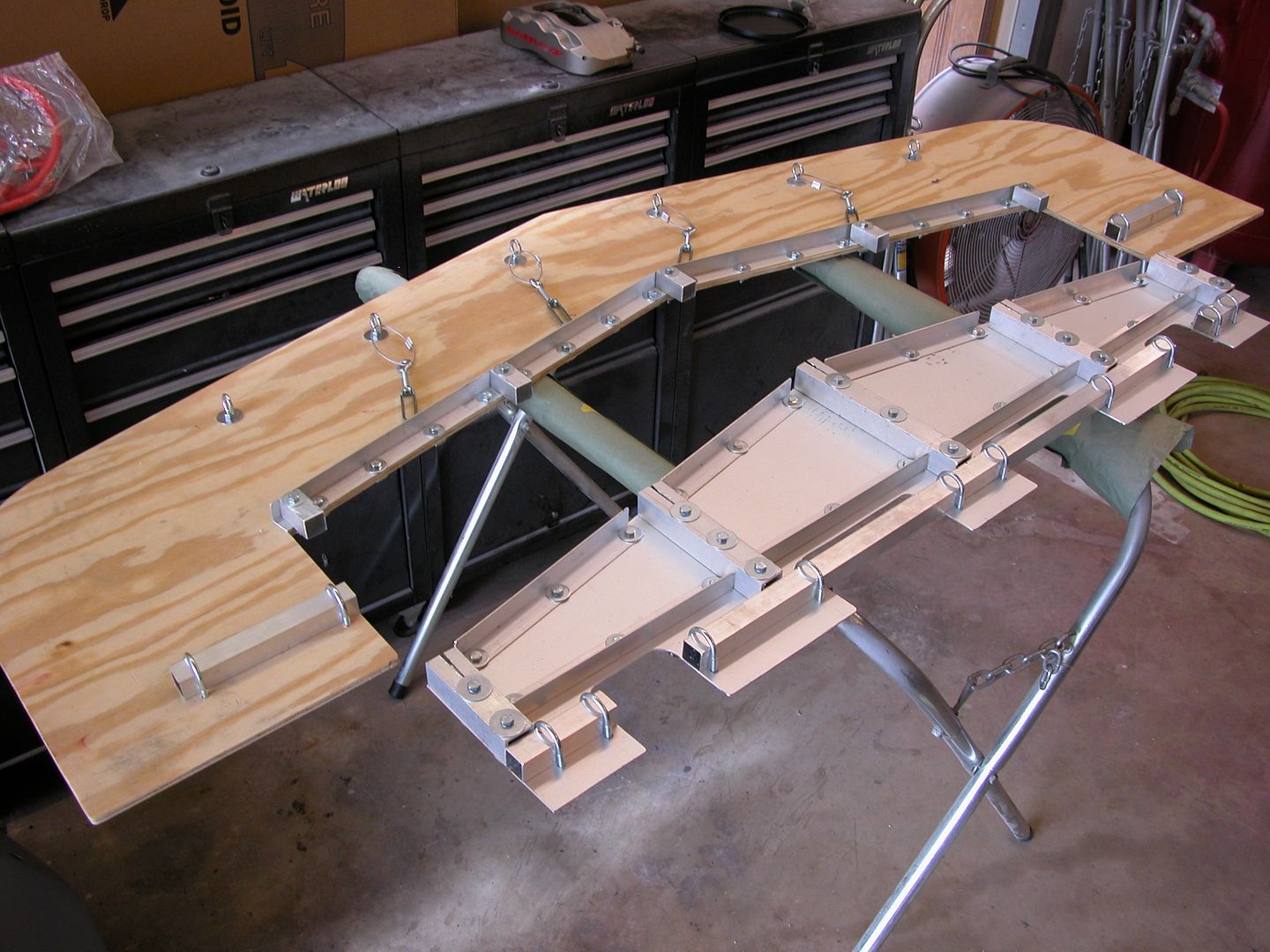 [/URL]
holy E36 M3. Today I learned that this car is still a thing.
golly!!!!
EricM wrote: holy E36 M3. Today I learned that this car is still a thing. golly!!!!
Oh ya, it's still "A THING!" alright. I've been working away on it but so many different aspects at the same time. So I waited to post until I could show some projects in their entirety. Like this brake duct project.
Continuing to catch up on posting progress I'll move on to the front brake duct cooling system.
The Baer brakes are large by huge 14" rotors with 6 piston calipers. The rotors are the curved vane type which are designed to move air from the rotor hat through the hollow vanes in the rotor to cool the rotor as long as it's turning. I want to have additional cooling ducts ta aid cooling for several reasons.
A. The aero changes I'm making will reduce the air exchange in the wheel wells. So that might contribute to the rotors, pads and calipers heating more than without the aero changes.
B. I'm running 285 front tires on 18" X 10" wheels that just barely clear the calipers. So the calipers and rotors are kind of shrouded by the wheels which might reduce cooling.
C. With the Yokohama AO 48 DOT R sticky tires I can brake harder during threshold braking before lock up than I would be able to with higher tread wear tires so more heat is generated.
D. Keeping the rotors and pads cooler should extend their life.
E The car is is stock bodied with no lightweight fiberglass or carbon fiber and propelled by an iron headed Pontiac engine so at 3500 lbs + it's no featherweight race car, yet I'll treat it like one on track.
Here's the basics of what I've done.
Remove the speed sensor mount to open up more space for a 3" brake duct hose.
Make backing plate for the rotor hat that has minimal clearance with a tube to attach the hose.
To attach the backing plate I used a threaded boss in the spindle (supplied by Baer with their package) and drilled then tapped two bolt holes in the caliper abutment so the backing plate has three bolts holding it.
Modified a couple dashboard vent ducts from mid 80's GM trucks so the 3" brake duct hose would fit on them. They're slightly too big for the duct hose stock so a few V cuts and they can be squeezed just enough to get the hoses on.
Mounted the duct opening vents in the core support up high right next to the radiator on each side. This is a high pressure area behind the grills which isn't affected by the bow wave at the very front of the bumper or air dam. I'd originally planned on using the park/turn signal openings however a discussion with Ron Sutton about the bow wave influence and the reduction of pressure on the splitter just below the signal opening caused me to change plans.
I've built everything using 3" 300 degree brake duct tubing. It's a tight fit by the outer tie rods and sway bar ends snaking a 3" tube in there with such wide wheels/tires. I checked turning radius, suspension travel considerations, and such but I may find that I need to downsize to 2" tubing. So I'm going to test with the 3" and if all's good make a prettier set of backing plates welded instead of riveted. If there's clearance issues I'll move down to 2" ducts and add inline fans.
Here's the pics!
Spindle with speed sensor mount in pic below.
[URL=http://s240.photobucket.com/user/NOTATA/media/The%2014%20Car%20Performance%20Therapy/001_zpsrjoqy6rx.jpg.html]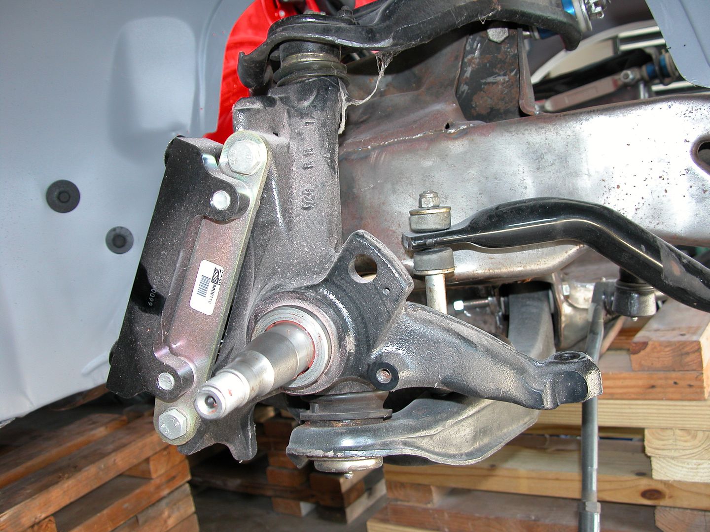 [/URL]
Speed sensor mount removed (but opposite spindle).
[URL=http://s240.photobucket.com/user/NOTATA/media/The%2014%20Car%20Performance%20Therapy/022_zpsnfvxbq5d.jpg.html]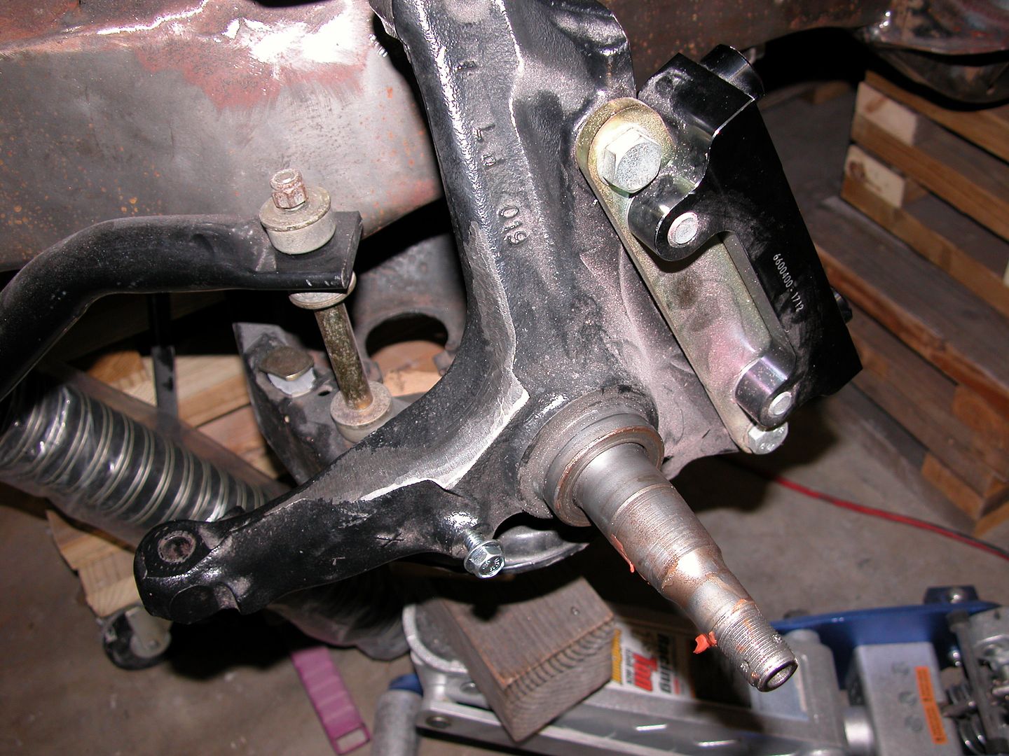 [/URL]
White line in pic below shows how much of the rotor hat is blocked by spindle arms, caliper brackets, and abutments.
[URL=http://s240.photobucket.com/user/NOTATA/media/The%2014%20Car%20Performance%20Therapy/013_zps1aslc5cq.jpg.html]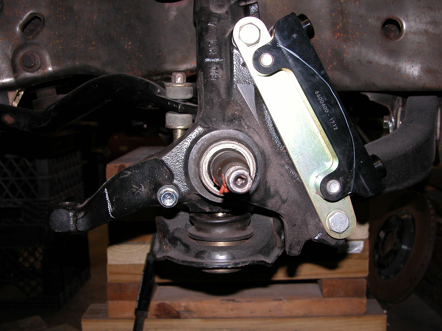 [/URL]
[URL=http://s240.photobucket.com/user/NOTATA/media/The%2014%20Car%20Performance%20Therapy/003_zps22ieiyqg.jpg.html]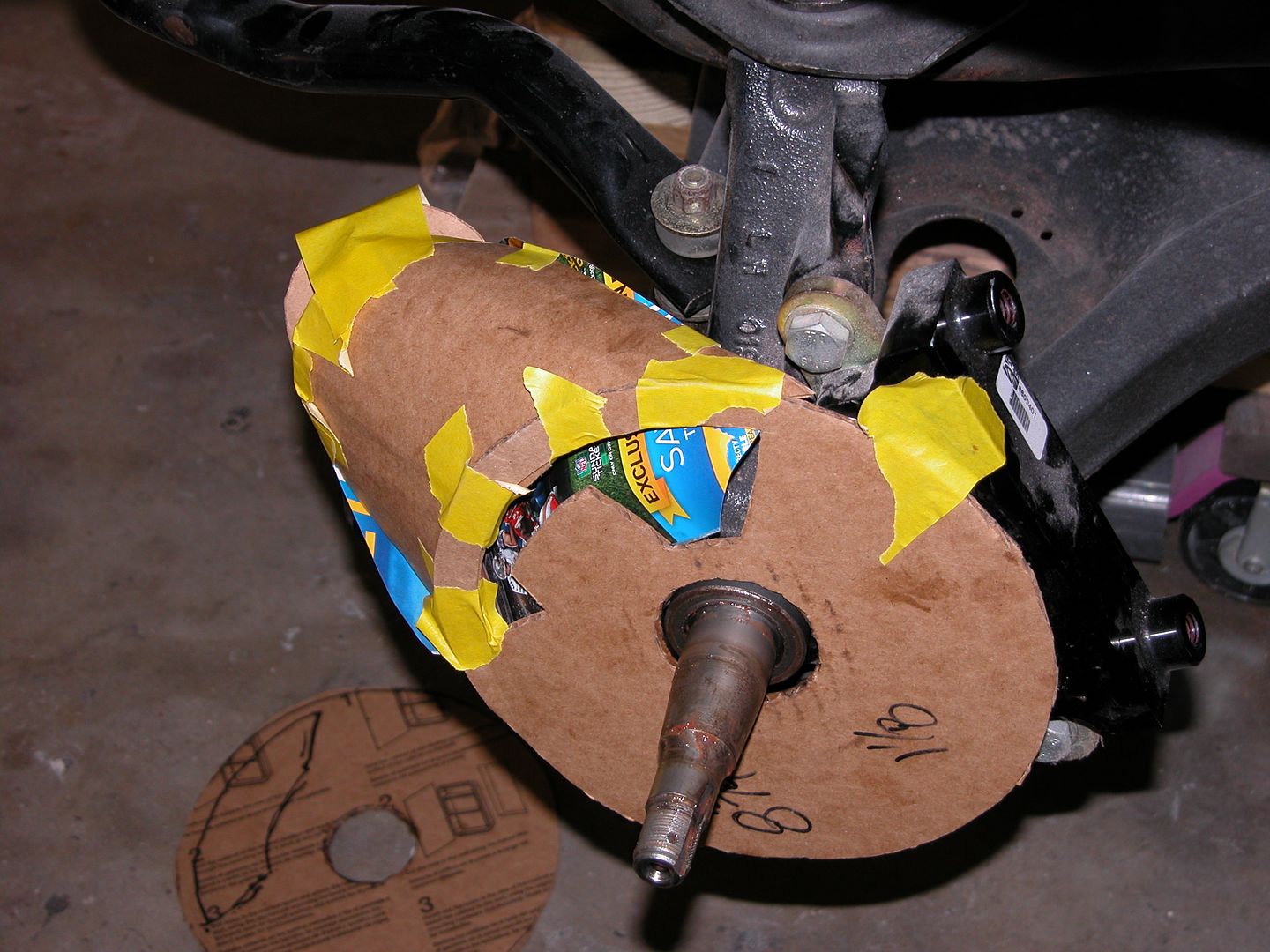 [/URL]
[URL=http://s240.photobucket.com/user/NOTATA/media/The%2014%20Car%20Performance%20Therapy/003_zpsakcacjs1.jpg.html]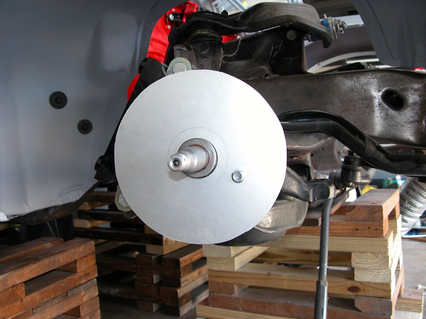 [/URL]
[URL=http://s240.photobucket.com/user/NOTATA/media/The%2014%20Car%20Performance%20Therapy/011_zpsoydfulit.jpg.html]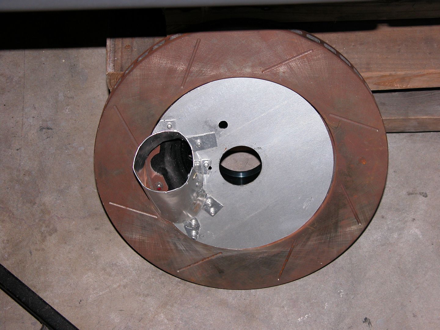 [/URL]
[URL=http://s240.photobucket.com/user/NOTATA/media/The%2014%20Car%20Performance%20Therapy/014_zpsks4vfsyb.jpg.html]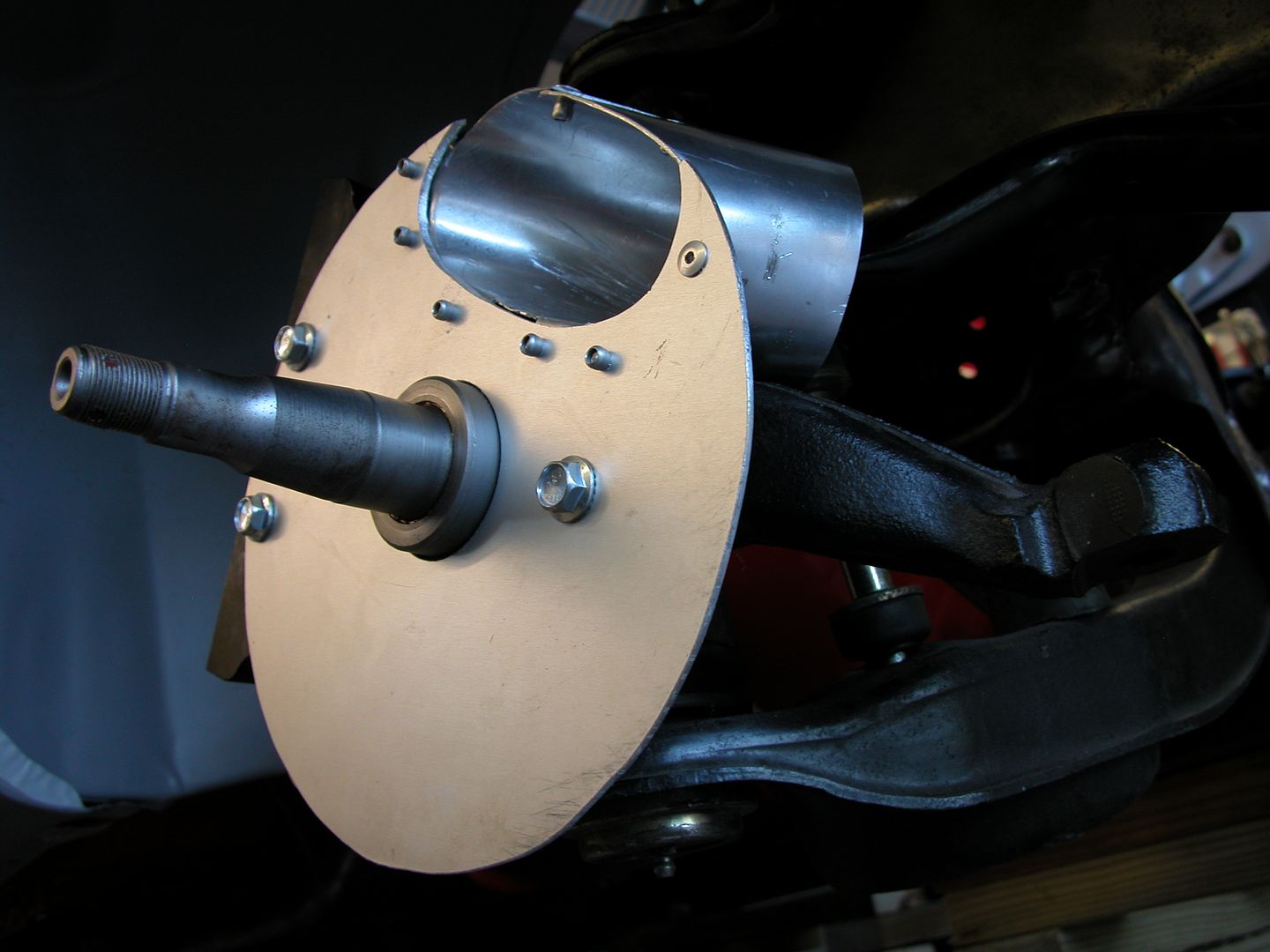 [/URL]
[URL=http://s240.photobucket.com/user/NOTATA/media/The%2014%20Car%20Performance%20Therapy/016_zps81sxtw1o.jpg.html]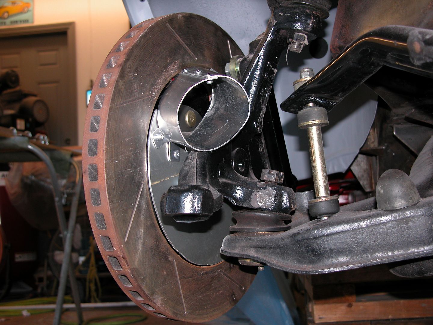 [/URL]
[URL=http://s240.photobucket.com/user/NOTATA/media/The%2014%20Car%20Performance%20Therapy/004_zpsaxq1s3fe.jpg.html]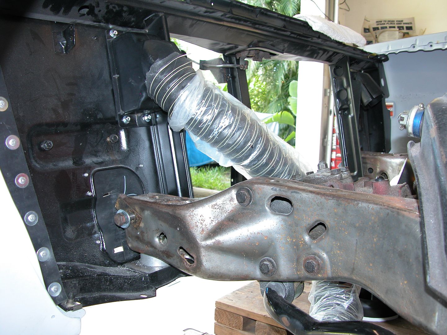 [/URL]
[URL=http://s240.photobucket.com/user/NOTATA/media/The%2014%20Car%20Performance%20Therapy/002_zpsky9bngkj.jpg.html]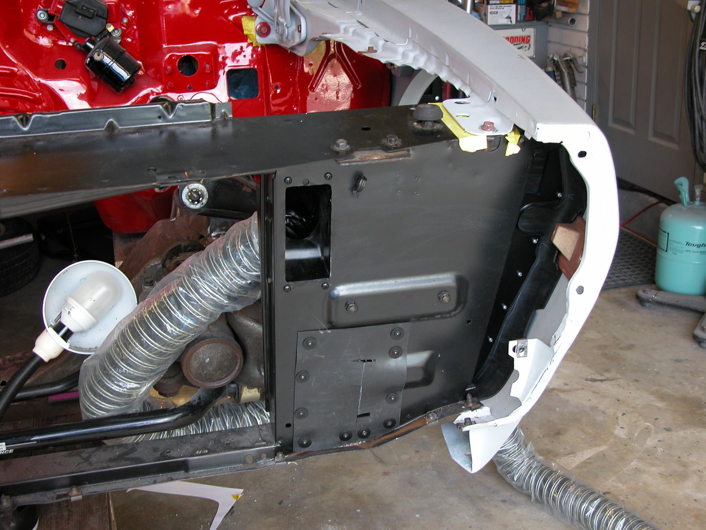 [/URL]
Looks great!
Sorry for the lack of response on your splitter pic request. Didn't see it until just now.

Thanks for all the writing on this thread. Sometimes I'm guilty of cruising for pictures and whenever I come across one that makes me scratch my head I just scroll back up and find a good, well though out explanation. Case in point. The location of the brake ducts. High pressure and avoiding the bow wave. Good stuff.

I love this thread. So many great ideas being documented and explained. Ill be using this thread for reference when I start diving deep into my own track cars.
Thanks for the great read!
Thanks! Always good to hear people like the thread! Onward with continuing to get the thread caught up to actual progress.
I wanted to seal off the openings on the top of the cowl where fresh air enters. This will increase air pressure on the top of the cowl so I'll get more down force in conjunction with a new hood to cowl seal which will be installed after final paint. I decided to use a reproduction screen I already had and modify it to seal off the openings. I used 3/32 EPDM rubber sheet and it's held in place with # 10 - 5/8"Phillips pan head screws and nylock nuts with 3/16" body washers to spread out the clamping force. The higher the air pressure, the tighter the seal will be. The car very rarely ever gets wet so I'm not concerned too much with drainage but if I'm on a trip and it rains I'll just pop the screen out.
Here's the pics!
[URL=http://s240.photobucket.com/user/NOTATA/media/The%2014%20Car%20Performance%20Therapy/005_zpsttzxlneu.jpg.html]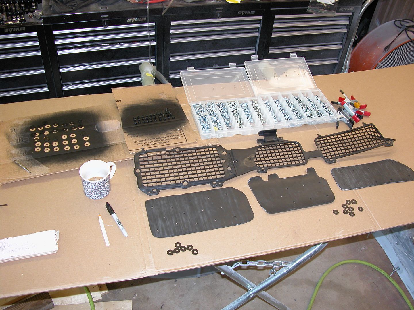 [/URL]
[URL=http://s240.photobucket.com/user/NOTATA/media/The%2014%20Car%20Performance%20Therapy/015_zpsdymqh7os.jpg.html]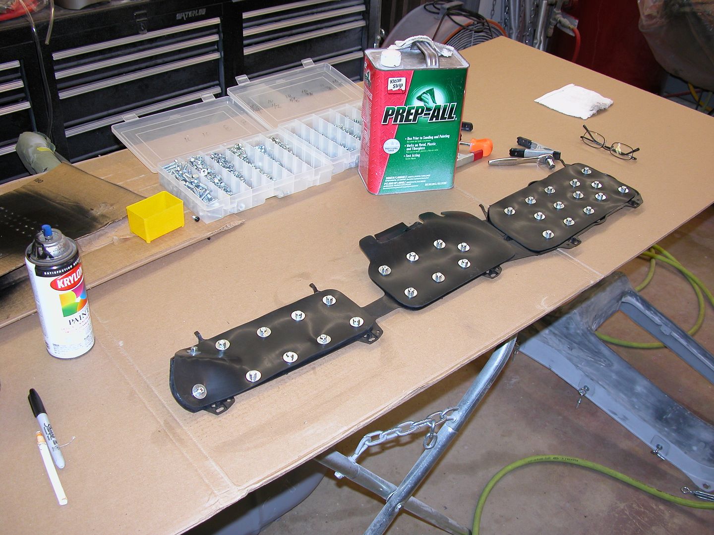 [/URL]
[URL=http://s240.photobucket.com/user/NOTATA/media/The%2014%20Car%20Performance%20Therapy/016_zpsaqwvw0ce.jpg.html]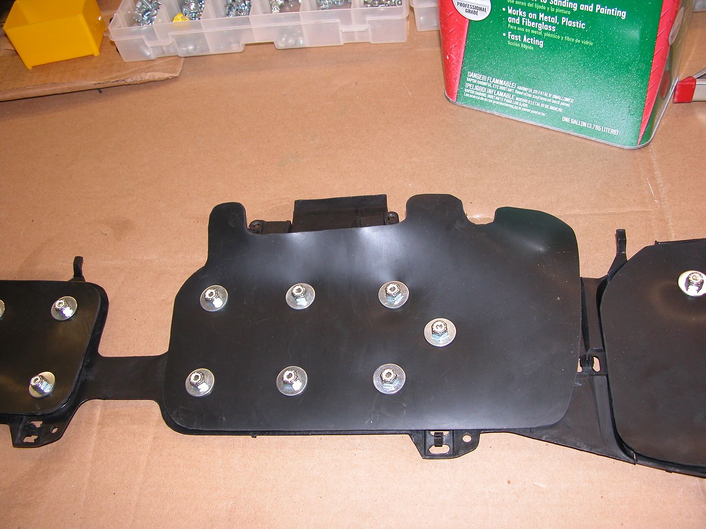 [/URL]
[URL=http://s240.photobucket.com/user/NOTATA/media/The%2014%20Car%20Performance%20Therapy/011_zpsebvhimkx.jpg.html]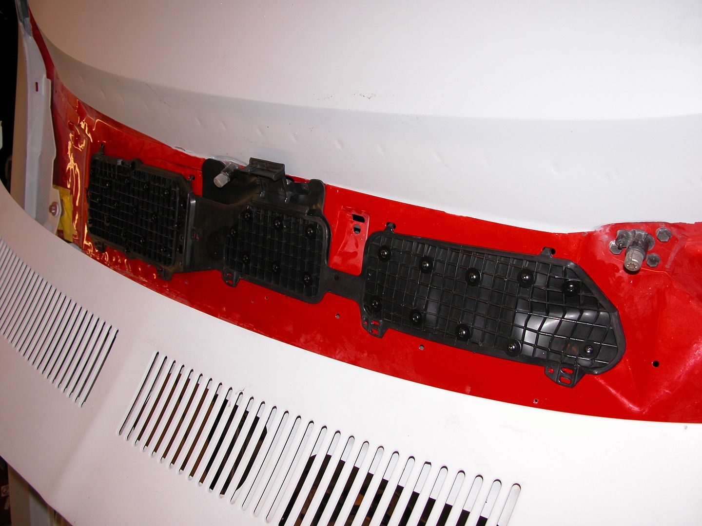 [/URL]
You'll need to log in to post.


