1 2 3 ... 5
Keith Tanner
Keith Tanner GRM+ Memberand MegaDork
2/26/21 9:52 a.m.

I like to learn by doing. I'll come up with a thing I want to do, then learn what I need to do to accomplish that. It can take me down some interesting roads and leave me with a collection of odd skills that are difficult to explain. I could start riffing on educational theory, but this is a car forum :)

The speedometer in the Targa Miata doesn't work. That's because an NA Miata has a mechanically driven speedometer and a T56 has an electrical sender. There are a few ways around this - retrofit the almost-but-not-quite-identically-shaped NB cluster, or drive a speedo cable using a motor in a "gerbil box" - but I've never implemented one.

Meanwhile, the advent of the open-wheel Tipo 186 monoposto kit got me thinking about how to emulate a chronometric tachometer - basically, a clockwork driven tach that only updates every second or so. You can see them in the opening sequence of Grand Prix, for example. Stack makes a tach that pretendes to be one of their old chronometric tachs up to 4000 or so, then it becomes a proper stepper-driven real tach for driving hard instead of hard parking.

Both of these got me thinking about using a stepper motor for gauges and how that would work. This would require learning some new and interesting skills. And then it snowballed.

This is the build thread for my analog race dash. At the time I'm starting this thread, it's not done. But I figured I'd invite you all along because the GRM brain trust has good ideas and a deep level of knowledge and hey, my wife just doesn't get excited enough when I tell her about my progress so I'm counting on all of you.

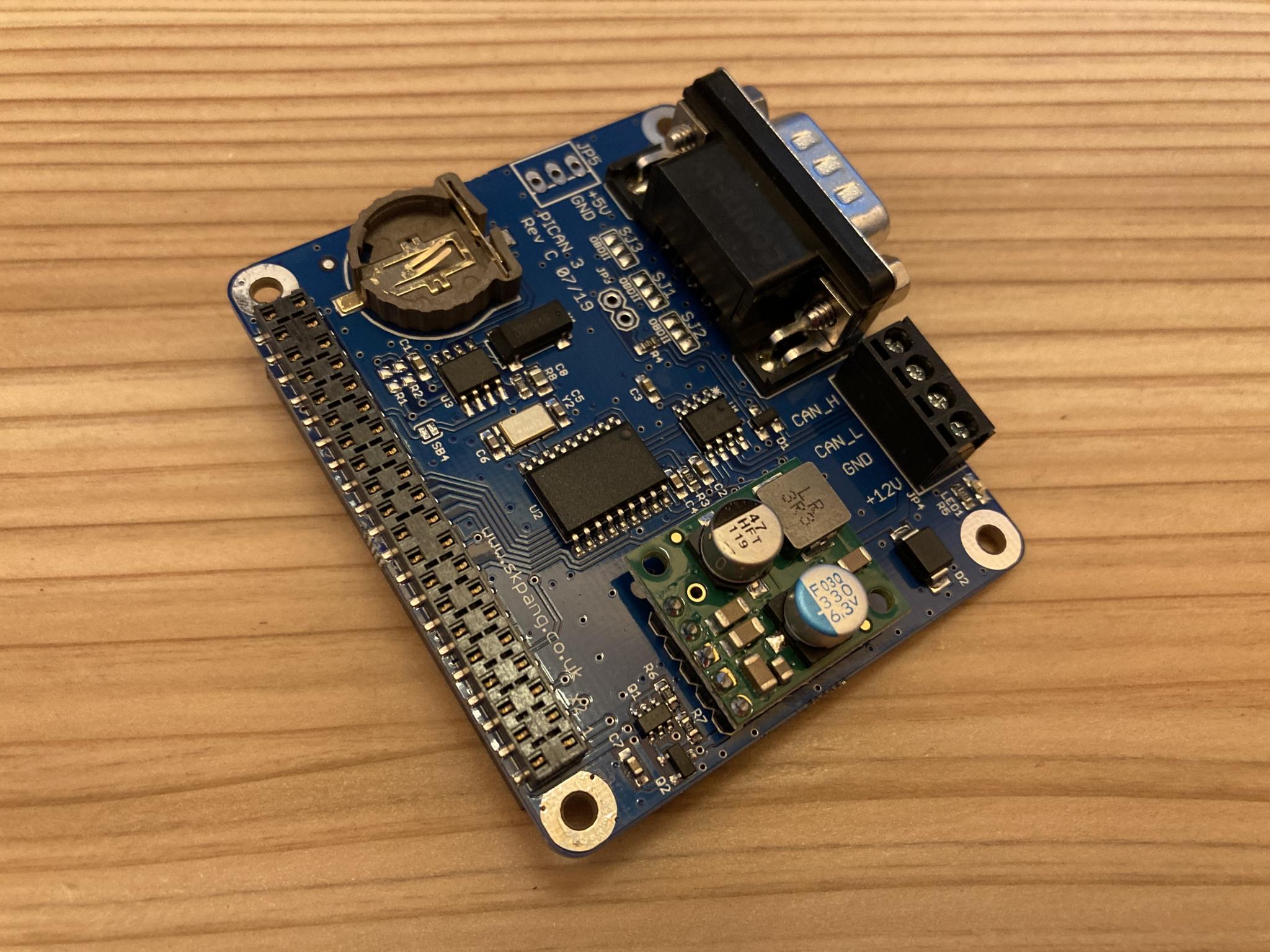
I decided from the start that I'd use a Pi to run the dash. Why Pi and not Arduino? Because a Pi is closely related to the grown-up computers I use on a regular basis and I have a certain level of familiarity with the platform. It also makes my new skills more transferrable. Besides, I can do a lot of stuff with a Pi. My race dash could double as a dash cam, for example. Or a music source. Or it could download a log of a drive when I park in the garage. Whatever. Pis bring a few of their own challenges but I'm cool with that.

So let's get started...

stafford1500
stafford1500 GRM+ Memberand Dork
2/26/21 9:59 a.m.

Anticipation, you've built some

Keith Tanner
Keith Tanner GRM+ Memberand MegaDork
2/26/21 10:01 a.m.

The first step was to figure out how to use stepper motors. I started with a Pi, some automotive stepper motors and a stepper motor hat (aka control board). I decided to use Python to run this because it's well documented and there are good libraries to use.

Steppers are weird, you can't just say "go to 90 degrees". You have to know how many steps they have, where you are and where you want to go. Then you tell it "step". Then "step". Then "step" until you get there. My stepper motor covers 315* of sweep and has 600 steps. So here's the pseudo code:

on startup, sweep the motor 600 steps clockwise and then 600 steps counter clockwise. This calibrates the motor so I know it's at zero. Everything is done via dead reckoning after this point.

Now I want to go to x rpm. I figure how many steps that is from 0, then tell the motor to "step" that many times. Then update my position in memory.

Time to go to y rpm. Figure out steps from zero, then find out how far that is from the last position I saved in memory, then step forward or backwards. 

Weird.

Anyhow, it wasn't too long before I had a way to tell the tach to show a certain RPM and it would swing over there. 

Why use a stepper instead of the "air core" gauges used by Mazda that just need specific voltages? Because I wanted to learn more about steppers. Maybe I'll expand this to air core in the future.

Jesse Ransom (FFS)
Jesse Ransom (FFS) GRM+ Memberand UltimaDork
2/26/21 10:02 a.m.

Awesome! Looking forward very much to following along.

EDIT: that was a fast next post. Already enjoying following along.

Keith Tanner
Keith Tanner GRM+ Memberand MegaDork
2/26/21 10:27 a.m.

There will be a few posts to get us up to today. I started working on this in December. And I just discovered that I have some pictures, which are always more fun.

Explaining the thought and development process helps me clarify my own thinking, so thanks for your patience.

Here's the stepper control hat. It's a pretty handy thing, they had some extra space on the board so it has extra 5v, 3.3v and ground spots as well as some basic prototyping area. This is designed to sit on top of the Pi so it has the same footprint. I'm using a Pi 3 A+ because of the form factor. The hat is actually on a Pi 4 in this pic in case you're a pi peeper.

Two steppers hooked up to a Pi - a Pi Zero in this case. Once cool thing about the Pi is that it basically runs off an SD card, so if you swap the card into a different Pi you can scale up your CPU and your power needs.

Here's a short video of the tach going through the calibration and then doing a very clumsy imitation of idling, a throttle blip and a run through the gears. This is going at full speed so I can make sure it's responsive enough - I had a little trouble with that at first as I learned.


pres589 (djronnebaum)
pres589 (djronnebaum) PowerDork
2/26/21 10:53 a.m.

Is it hard, you think, to get the right amount of hysteresis into the system to not have the tech become a bounce-fest?

Keith Tanner
Keith Tanner GRM+ Memberand MegaDork
2/26/21 10:59 a.m.
pres589 (djronnebaum) said:

Is it hard, you think, to get the right amount of hysteresis into the system to not have the tech become a bounce-fest?

I think that's a function of how often the tach is updated. With 600 steps in the stepper and a 6600 rpm redline, each step is 11 rpm so that gives a little protection against jitter. Given that the tach is updated every 12.5ms (spoiler alert), I think it will be smooth. But experimentation will tell.

TVR Scott (Forum Supporter)
TVR Scott (Forum Supporter) GRM+ Memberand SuperDork
2/26/21 11:05 a.m.

I've got to do something similar.  I'll be interested in what you do here.

Keith Tanner
Keith Tanner GRM+ Memberand MegaDork
2/26/21 11:11 a.m.

What I'm doing here is developing the tools I'll use for this setup. How to actually use them will come once I have a better handle on my capabilities.

Next, LED control.

Wait, what?

I'm a big fan of sequential LED tachs like you see on F1 cars. You can see the one in the Targa Miata in this completely gratuitously embedded video.


I'd been looking for a reason to use some of the new LED arrays, so I decided to incorporate some. I picked up a 3" ring of APA102 LEDs, figuring that would sit nicely behind the tach needle. So then it was time to figure out how to control it. I didn't take too many pictures of this, but here's the backside of the LED array as I learn how to solder SMD capacitors.

These LEDs are basically networked. You send a series of bits down the data line along with a clock signal down the clock line. The LEDs keep a few bytes for themselves and pass rest of the signal down the line, so for this 60 LED array you basically say:
LISTEN TO ME
RGB value xxx, brightness x (LED 1 takes this one)
RGB value xxx, brightness x (LED 2 takes this one)
....
OKAY I'M DONE

It's almost but not quite the SPI protocol, so you can use the SPI bus built into the Pi along with the standard Python SPI library which makes it easy. But it's not quite the SPI protocol. This will become important. 

I decided I wanted a few different things for this LED ring to do:
- show rpm with different colors for different ranges (like my Revlight)
- have the brightness of the tach increase with RPM
- have a peak indicator
- have a variable redline that would change according to coolant temp (like an E39 M5)
- go into "freakout mode" if something goes out of range

I programmed and tested and played and came up with some options. Really, it's computer science 101 but I'm almost completely self-taught in this stuff so it's good to go back to basics because I tend to bump into holes in my skillset. Also, because the Pi is a little more limited in horsepower than full size computers it rewards efficient code, and I like working to build the cleanest code I can. The programming equivalent of good mechanical engineering.

I also have some "LED transparent" acrylic that looks matte black until you light something up behind it. I figured that would be a good gauge face. When I tested, it looked good. Here it is showing a bit of the temperature sensitive redline (blue) and indicating roughly 6000 rpm. I didn't have the brightness working quite right here.

I have some individual LEDs I could use as well as some display screens, but I think the ring will be a good start.

Keith Tanner
Keith Tanner GRM+ Memberand MegaDork
2/26/21 11:37 a.m.

Now, getting info from the car. I originally was going to read the ignition pulses and figure out the frequency and move the steppers and that dragged me down some paths I wasn't ready to work on yet. But the Targa Miata runs a GM PCM, which provides quite a bit of information via CAN and I know some of this stuff from our ND V8 work. I have spent a lot of time in the CAN world.

So let's hook the Pi up to CAN. For this, I went to a PICAN3, which is a hat that can send/receive CAN signals and also has an onboard power supply to run the Pi. This is convenient for in-car use.

Note that I'm planning to simply listen in on the chatter on the network instead of a generic OBD-II plug-in style. When an OBD-II scanner is plugged in, it requests data (GIVE ME ENGINE RPM!) and the PCM will respond (ENGINE RPM IS 5500!). But these responses are a low priority as they're intended for diagnosis and are inherently a little laggy.

The broadcast data is sent on a regular schedule so it's better to use. However, it is unique to each manufacturer which is why you don't see it used in things like a ScanGauge. These CAN protocols are not always public as we found with the ND Miatas, even contacts inside Mazda USA were unable to help. But in the case of GM, it is available in the Platform to Powertrain Electrical Interface Specification, aka GMW8762. 300 pages of dry info, but it tells you that Vehicle Speed Average Driven (aka ground speed) is found in message 3E9, 15 bits long starting on bit 6 of byte 0. Also that you multiply that number by 0.0156 to get speed in km. It's a LOT easier to look that up than it is to reverse engineer it, thank you GM. And no thanks Mazda.

So the next step was to plug this into the car and learn how to filter, read and work with the messages. This was fairly familiar territory, so it wasn't long before I had it displaying RPM on my laptop - I'm doing all this work "headless", which means the Pi doesn't have a screen of its own and I'm working from the command line a lot of the time.

By the way, the GM PCM broadcasts the engine RPM every 12.5 milliseconds. Lower priority data such as engine coolant temp could be every 500 ms.

Woo!

Keith Tanner
Keith Tanner GRM+ Memberand MegaDork
2/26/21 11:48 a.m.

But then I tried to hook up the LED ring - for packaging reasons, this was easier than getting the stepper motors working immediately. And I ran into an immediate problem.

The CAN hat uses SPI to communicate with the Pi and SPI is designed to allow for multiple devices on the same bus. But the CAN piece is literally hard-coded to use a certain bus. It's actually in the circuit board. And the LEDs use an SPI-type interface that doesn't allow for the use of different buses or slaves. Had either one of them been given any flexibility, it would have been okay. But no, both of them were quite stubbon. It was kind of entertaining, the LEDs would jitter around as they tried to interpret the data being passed from the CAN hat to the Pi but it wasn't useful.

Eventually, I had to create a separate channel to run the LED and "bit bang" the data - that means creating the bits and the clock signal manually by toggling pins on and off. That was an interesting piece of education. Basically, it works like this:

1101 is:
data pin goes high (voltage is turned on)
clock tick (clock pin goes high then low, aka voltage is turned on then off)
data pin goes high (stays high, really)
clock tick
data pin goes low
clock tick
data pin goes high
clock tick 

etc.

 With that done, this happened.

Here it is in action. The white dot is a peak indicator - it shows the maximum RPM value hit within the last 500 ms, which I feel might be useful when you're making sure you hit your shift points. And it was fun to code.


Keith Tanner
Keith Tanner GRM+ Memberand MegaDork
2/26/21 12:02 p.m.

Now it's time to bring the steppers back into play. This makes for a fairly solid chunk of hardware. It's still in prototype mode and I'll build a case for it later.

Here's a simulation of how the tach should work. It's running slow in this video which I would love to claim is to make it clear to see, but really it was a programming problem at that point.


How fast can it move? Fast enough that the slightly loose fit of the Miata tach needle on the non-Miata stepper motor causes the needle to slip on the spindle. 


And the real test - in the car. I have the peak indicator turned off at this point and I need to determine if there's a programming problem or if the needle slipped, but I'm pretty happy with this. We have a functioning physical and LED tach.


Keith Tanner
Keith Tanner GRM+ Memberand MegaDork
2/26/21 12:11 p.m.

So that's where I am now. I have the following capabilities:

- read and react to CAN signals
- display various info on an LED ring
- control the needle of an analog gauge

So what do I do with it? My current thought is to give the dash the following capabilities, but I am open to suggestions. Keep in mind that I can put a second LED ring behind the speedo as well, and it's possible to put a couple of concentric rings back there.

The current plan is:

- put the two main gauges in a normal Miata gauge cluster and leave the stock coolant temp, oil pressure and fuel sensor as-is
- tach as shown, with the peak indicator. 
- speedo as normal speedo, but actually working unlike what I have in the car now
- LED ring behind the speedo to work as a warning for out of range numbers (low oil pressure, high coolant temp, MIL, ????)
- maybe use the speedo LEDs to show current coolant temp?
- make the LEDs optional so it looks like a normal dash most of the time
- maybe put a small display in between the main dials

What would you do with these capabilities and the processing power now on board? The Pi can take a camera input, it can output HDMI video and regular stereo audio, it can connect to wireless networks or be a wireless access point, it can do most things a full computer can do.

Jesse Ransom (FFS)
Jesse Ransom (FFS) GRM+ Memberand UltimaDork
2/26/21 12:18 p.m.

Neat!

If it *hasn't* slipped, I wonder whether it's a matter of the stepper losing steps. I'm not terribly familiar with this stuff, but got a little education from This Old Tony's last update on CNCifying his old MAHO mill; specifically the distinction between steppers and servos, and the former's lack of feedback on whether it's achieved the steps it was told to.

I wouldn't think you'd have the CNC problem of actually encountering enough physical resistance that the stepper would fail to move through a commanded step, but if for some reason it gets to where it's out of sync, is there a good way to add a position marker that tells it regularly when it's at some specific point so errors in step-counting don't pile up?

Insta-edit to insert an apology for suggesting fixes for problems that don't exist.

pres589 (djronnebaum)
pres589 (djronnebaum) PowerDork
2/26/21 12:22 p.m.

This is super cool.  

Keith Tanner
Keith Tanner GRM+ Memberand MegaDork
2/26/21 12:47 p.m.
Jesse Ransom (FFS) said:

Neat!

If it *hasn't* slipped, I wonder whether it's a matter of the stepper losing steps. I'm not terribly familiar with this stuff, but got a little education from This Old Tony's last update on CNCifying his old MAHO mill; specifically the distinction between steppers and servos, and the former's lack of feedback on whether it's achieved the steps it was told to.

I wouldn't think you'd have the CNC problem of actually encountering enough physical resistance that the stepper would fail to move through a commanded step, but if for some reason it gets to where it's out of sync, is there a good way to add a position marker that tells it regularly when it's at some specific point so errors in step-counting don't pile up?

Insta-edit to insert an apology for suggesting fixes for problems that don't exist.

It may be skipping steps - I think that happens when I try to drive it at maximum speed, you can actually hear it. But that needle is a little loose, so I think what I'll do is a few test runs followed by a calibration so I can ensure the needle is staying in place. I've found that some of my needles fit more tightly than others so I have options there. These automotive grade steppers don't have a lot of torque and they came with quite a short needle, maybe it's struggling to whip that long thing around. 

Or maybe I have a programming error slipping in :)

I could potentially use a microswitch on the needle to tell when it gets to a certain point, but in regular operation it won't visit the extremes in travel so I'm not sure that will help. Step 1 is to diagnose the problem, which will be fun.

You speak in a strange new language I only sort of understand. I can honestly say I'm smarter than before I opened this thread. Thank You, and carry on.

Keith Tanner
Keith Tanner GRM+ Memberand MegaDork
2/26/21 1:53 p.m.

I learned most of what I know by asking questions of people who already knew - so if I can help, ask questions. That may illustrate things I got wrong or understand better after I attempt to explain, so we both benefit :)

APEowner
APEowner GRM+ Memberand Dork
2/26/21 2:52 p.m.

Cool project! 

I've been toying with doing an LED tach in my Formula Ford.  The cockpit is so small that there's really only room for one critical gauge.  Right now it's occupied by the tach but I'd really like to be able to see the Tracmate display while I'm driving.  I'm thinking about putting the Tracmate centered where the tach is now and putting an LED bar graph tach on the steering wheel.


paddygarcia
paddygarcia GRM+ Memberand New Reader
2/26/21 6:32 p.m.

Very cool project!

Keith Tanner
Keith Tanner GRM+ Memberand MegaDork
2/26/21 7:33 p.m.

I'm going to keep playing with the steppers to see if I can keep them from skipping - if that's indeed what is happening. I may have to source a different motor if I persist in using long needles on rapidly moving gauges. Free-revving in neutral is a worst case scenario, so as long as I can keep up with that I'm good.

I'm not building my own circuit boards from scratch, so building a reflowing oven isn't necessary...yet. I'm getting away with a soldering iron and a magnifying lens. I just had to add a capacitor to the LED ring to make sure it could deal with rapid spikes in power demand - ie, lighting up the whole ring in a flash.

I actually get the speed signal for the rally computer already in the car from a modified ABS ring. But it also has a speed input into the PCM from the transmission so I just need to pull that out of the CAN messages. No need to count pulses, once you're into the network a bunch of stuff gets much simpler!

Keith Tanner
Keith Tanner GRM+ Memberand MegaDork
2/26/21 9:02 p.m.

Did a little experimentation, I think it's skipping even though I'm using the "high torque" method of driving them. Reading up on the causes, one of them is potentially a power problem. Okay, the hat I'm using should be able to deliver lots of power - but I'm going to separate the LED power supply from the stepper motor just to make sure the hungry LEDs aren't causing problems. I'm also going to solder wires straight to the stepper motor poles instead of relying on a breadboard just in case I don't have a solid connection.

I also looked up the part number. Turns out this motor is used in a bunch of Silverados, etc. So it certainly should be up to the job. And that might be a good source of needles. Anyone got a 2003-06 Silverado/Tahoe/etc gauge cluster they don't need?

nocones
nocones GRM+ Memberand UberDork
2/26/21 9:22 p.m.

In reply to Keith Tanner :

Isn't that the generation of silverado dash that has issues with stepper motors eating dashboard modules?

(This is based on my ownership of a 2008 e3500 and the research I did when it's dash was acting wonky.  That was one failure mode it could have been but it turned out to be a 5v problem in the com bus caused by the Throttle body)

Keith Tanner
Keith Tanner GRM+ Memberand MegaDork
2/26/21 9:32 p.m.

Let's just say that replacement units are freely available due to high demand. But I don't need to to last 100,000 miles, so I'm hoping they'll last for a few years. I've ordered a few more just in case I'm doing all this testing with a bum unit - they're only a couple of bucks each. 

obsolete
obsolete GRM+ Memberand Reader
3/1/21 10:24 a.m.

Eager for updates on this. Really cool project.

1 2 3 ... 5

You'll need to log in to post.

Our Preferred Partners
xwWiqXDGD1KgS5aqED6hWx8GFkfDFbli7OMbOsmWTsWqHBIklDqgkRvJN35aIYkj