1 2 3 4 5
burdickjp
burdickjp GRM+ Memberand Reader
1/30/20 8:13 p.m.

Some interesting notes as I pull the engine down:

The upper water neck and thermostat are built into the intake manifold. The EGR is built into the exhaust manifold, back of the cylinder head, and intake manifold.

The turbocharger is truly tiny. I'm hoping to do some modifications to this one and fit it to the first iteration of the engine.

The intake ports are rather narrow with respect to the valves. This isn't a very good picture of it. I'll try to get some good lights and a macro lens together to get better port pictures. One thing this does show is that the gasket is a very good match to the head, but the intake manifold is atrociously out of line with the ports.

Recon1342
Recon1342 HalfDork
1/30/20 9:28 p.m.

In reply to burdickjp :

That turbo is tiny! I could probably hook it up to the AIR line on my 360 and run it...

burdickjp
burdickjp GRM+ Memberand Reader
2/2/20 8:07 p.m.

I got the engine torn down this weekend. I took some more crappy phone pictures while going through it. Once I get everything cleaned up I'll take some better pictures and put together a proper write up.

Considering that this is a 657 cc engine and it's made by Suzuki, I was expecting things to resemble a motorcycle engine design-wise. It does not.

The camshafts on this engine is timing belt driven. Here on the front of the engine we can see that the water pump is driven by the same belt and the back of the impeller housing is cast into the block, similar to a Honda B or D series engine.

There is no valve cover to this engine. The camshafts are captive in cam boxes which bolt to the top of the engine.

Here's the camshafts chilling out in their boxes. The shafts slide into these boxes from the flywheel side. Plates are then bolted on which hold any thrust loads. The way these are constructed means cam lobes must fit through the bearing journals on the boxes. This would be a limit to the cam profile.

Here's where those cam boxes bolt to. Rockers sit over those valve stems, pivoting on those hydraulic lash adjusters. This geometry means there's a minimum base circle  for which this mechanism will operate. Between this and the cam box journals is the maximum lobe lift.


The valve springs are rather large in diameter for this valve size. There should be generous room for whatever is necessary to rev this thing to the moon.

The combustion chambers are rather conventional. There's squish pads all the way around. I'm not a fan of heads which push the exhaust valves to the edge of the chamber like this. I prefer them to be closer together, maximizing clearance around the valve curtain.

The block is cast iron. It's a color I haven't seen before.

The block casting seems to be of a very high quality, with very little casting flash and some interesting geometry around the bores. I'll still be doing some grinding to clean up what flash is there and smooth some sharp corners.

burdickjp
burdickjp GRM+ Memberand Reader
2/10/20 7:10 p.m.

I dropped the block, head, and crank off at a shop for cleaning. When they come back I'll start casting the chambers and ports in silicone.

I'm putting together a setup for measuring the cam profile. I need to know the lift at the valve and the lift at the cam. The rocker has a rounded profile that the cam acts against, and a rounded section that acts against the valve.

I'm trying to put together a method of measuring the geometry of the rocker on my surface plate with a height gage. This will allow me to model the cam profile in CAD and determine the limits of the cam profile this rocker arrangement will allow.

ill_climber
ill_climber New Reader
2/10/20 11:24 p.m.

I can see this getting interesting. Carry on!

burdickjp
burdickjp GRM+ Memberand Reader
2/12/20 8:25 p.m.

Alright!

I put together a setup on my surface plate this evening to measure the valve rocker ratio. Let's talk about it.

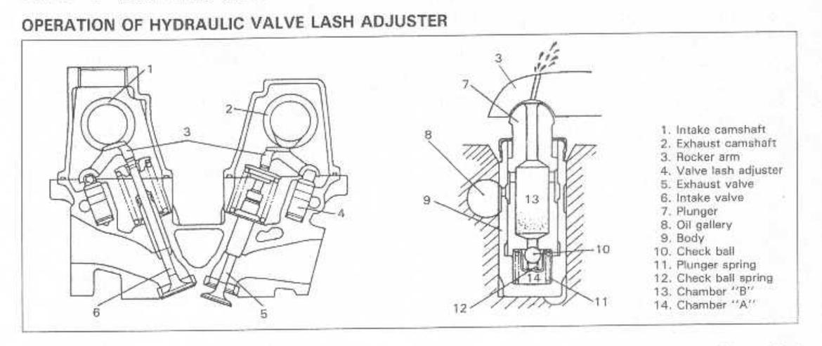
Here's a snip from the factory service manual. You can see that the lash adjuster and valve sit in parallel bores in the cylinder head. Also, when the valve is closed the tips are nearly level.

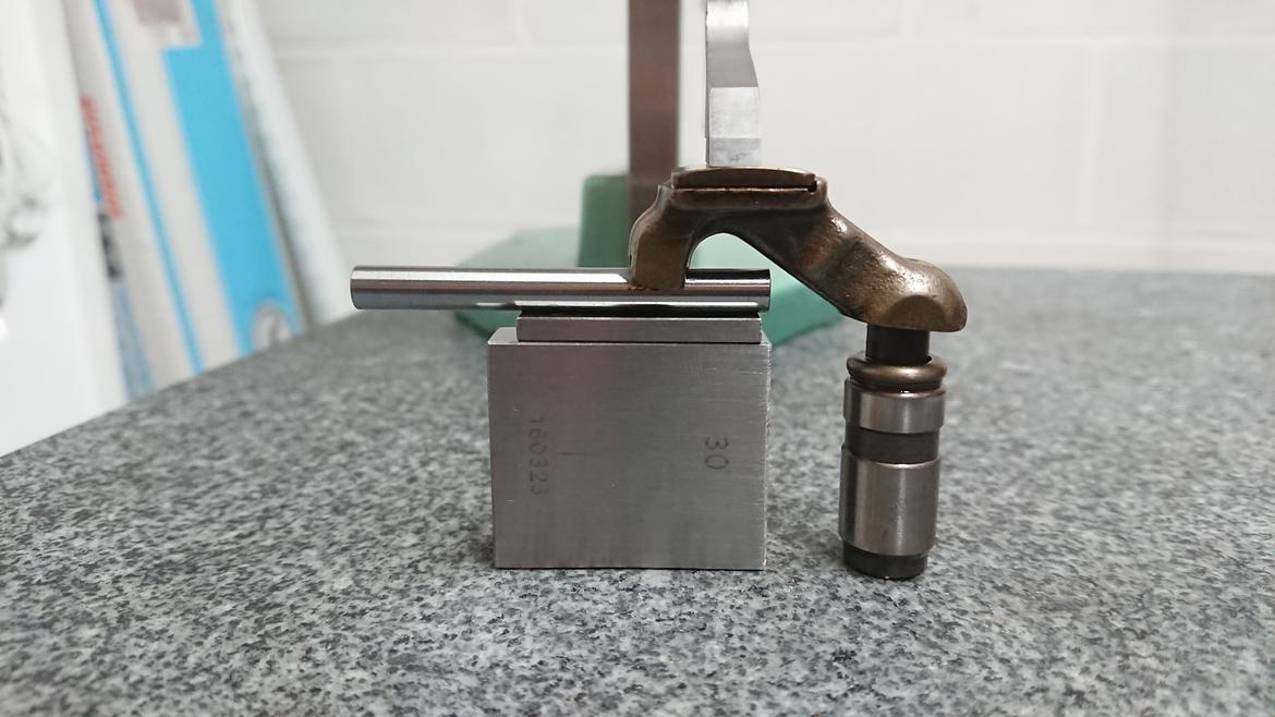
On the right is the lash adjuster. On the left are a stack up of gage blocks. My gage blocks are wider than the round pad that the valve rests on, so I'm using a 5.5 mm gage pin. The pad is round in profile, so this creates a point contact.

I lower the height gage down onto the cam pad. The pad is round, so this creates a line contact. With the lash adjuster resting flat, the whole configuration is well constrained. I read the height gage, rinse, and repeat. As the height of the gage stack changes the highest point on the cam pad moves from one side to the other. You can see this by where the line contact of the height gage is on the cam pad. At the smallest amount of valve lift the highest point is closest to the valve side. At the largest amount of valve lift the highest point of contact is closest to the valve adjuster.

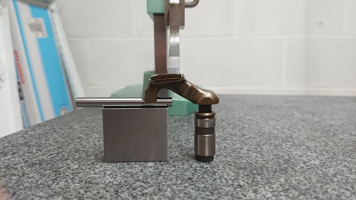
This means that the valve lift ratio is smallest at lower lifts and highest at larger lifts. I calculated the rocker ratio by finding the difference in height gage readings. At lowest valve lift the rocker ratio is very nearly 1:1. At highest valve lift the ratio is nearly 2:1.

The camshaft has a 26 mm base circle and is 30 mm nose-to-heel. That's 4 mm of cam lift, which seems tiny, but it's 8 mm of valve lift! That's better!

Would we be able to do better?

The way that the camshafts fit in the cam box means that the the cam lobes must fit through the bearing journals:

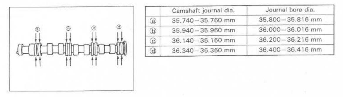
The lobes to the left of journal bore b must fit through b. That bore is 36 mm in diameter at its smallest. 36/2 = 16. We can have a cam lobe with a nose radius of 16 mm. If we keep the same base circle of 26 mm we have a nose-to-heel dimension of 31 mm. 31 - 26 is 5 mm. That'd be 10 mm of valve lift. We can gain 2 mm of valve lift if we can weld the cam lobes, keeping the base circle the same! If we can reduce the base circle we could go even bigger!

I would need to find the limit of the lash adjuster to know how small I can make the base circle.

Next on the list of tasks is measuring cam lift and valve lift. This will confirm my rocker ratio measurements and help determine what my next cam profile will be. Then I can shop around with cam grinders to see who can help me weld up and grind a set of camshafts.

I'm also considering cutting up a lash adjuster to see about replacing the hydraulic action with some kind of internal shim setup.

burdickjp
burdickjp GRM+ Memberand Reader
2/13/20 7:08 p.m.

Block, head, and crankshaft came back from the cleaner this evening.

I hade some silicone RTV casting compound on the shelf. It's pretty old and my shop is pretty cold, so it didn't mix well. I've ordered more for the exhaust port and combustion chamber.

I did some quick crank measurements. Not yet ready for doing real measurements, but I want to know if there's any room for polishing or even regrinding.

The main journals are 44 mm nominal, so I made a 44 mm gage block stack and zeroed my micrometer off of it and measure the mains. Then make a 38 mm stack and measure the crankpins.

Looking good there!

The crank has single oiling holes on the crankpins. This isn't uncommon, but isn't as sophisticated as, for example, a 4A-G crank, which has cross-pin oiling. The main bearings are 360 degree grooved, though.

Intake ports have a definite sharp corner transitioning from the bowl to the short-side radius but there's a good, gradual, and easy to blend short-side radius. There's only the valve seat angle and a top angle. The chambers have a pronounced "eyebrow" between valve seats. Bowls could use a lot of blending. Even so, I'm very excited to sink my carbides into it.

The exhaust side isn't very different. An exception is that the exhaust port face is actually pointed down. The face isn't normal to the cross-section of the port, so I'll be correcting this when I construct my exhaust manifold. I guess I'll have to CNC a flange! Oh, darn!

Recon1342
Recon1342 HalfDork
2/13/20 9:49 p.m.

In reply to burdickjp :

I love the thought process you're going through with this. It seems as if you're  taking a go-kart and turning it up to 11, and those are my kind of shenanigans.

There is a very real part of me that wants to hot-rod a Chrysler Flathead six for the exact same reasons...

burdickjp
burdickjp GRM+ Memberand Reader
2/14/20 9:07 p.m.

If you were looking at that casting mold and thinking "That's never going to work" you were right. I now know that if it's well expired and the shop is too cold then it isn't going to work.


I spent some time tonight trying to dig it out of the port. It's going to take a long time. The good news is new silicone is on the way from TAP Plastics.

burdickjp
burdickjp GRM+ Memberand Reader
2/21/20 9:45 a.m.


I had a friend grab a scan with a Hexagon arm last night.

burdickjp
burdickjp GRM+ Memberand Reader
2/22/20 9:38 p.m.

This weekend I pulled the scans into Rhino and started extracting geometry.

Also, my new engine and transmission showed up, so I will be putting them in the car to get it on the road ASAP.

burdickjp
burdickjp GRM+ Memberand Reader
2/24/20 1:14 p.m.

Got the engine and transmission bolted together and bolted into the car. Now it's hoses, lines, wires, and tubes. Then we're on the road!

clutchsmoke
clutchsmoke UltraDork
2/24/20 1:38 p.m.

It's always good to have a spare around in case the high performance endeavors decrease reliability somewhat. 

Excellent work so far!

burdickjp
burdickjp GRM+ Memberand Reader
2/25/20 11:56 a.m.
clutchsmoke said:

It's always good to have a spare around in case the high performance endeavors decrease reliability somewhat. 

Excellent work so far!

Playing with engines is my idea of fun. Cars are the facilitator to playing with engines.
So I tend to have 3 engines for my project cars:

One in the car.

One on a stand, ready to go in.

One in the process of development.

burdickjp
burdickjp GRM+ Memberand Reader
3/25/20 5:28 p.m.

IT RUNS!

But I can't get it titled and plated because the county clerk's office is closed until the pandemic cools down.

Kenny_S2K
Kenny_S2K New Reader
3/26/20 8:15 a.m.

I need to get mine up and running again, have 95% of it ready so I can drop the engine, then I am going to carefully inspect and replace every rubber hose and connection so that I don't have to mess with it in a long long time.

burdickjp
burdickjp GRM+ Memberand Reader
3/31/20 8:59 a.m.

I've been taking it for clandestine rolls around the block.
I can't plate it right now because that office is closed.


It needs an alignment, for sure. My shop isn't flat enough for that so I either build leveling stands or take it somewhere flat.

Glanced at this thread before, but now I'm following with serious interest! Ordered my EA21R today, should be here later this year! Really excited right now, and glad to see another Cappuccino in here. I've heard various things regarding how different the K6A is...I know for sure it is alloy block and chain-driven cams. Some sources indicate most everything else is shared with the EA11R, but I'm taking that with a grain of salt-shaker at the moment.

burdickjp
burdickjp GRM+ Memberand Reader
1/10/21 8:16 p.m.
ae86andkp61 (Forum Supporter) said:

Glanced at this thread before, but now I'm following with serious interest! Ordered my EA21R today, should be here later this year! Really excited right now, and glad to see another Cappuccino in here. I've heard various things regarding how different the K6A is...I know for sure it is alloy block and chain-driven cams. Some sources indicate most everything else is shared with the EA11R, but I'm taking that with a grain of salt-shaker at the moment.

I want to dig into a K6A as soon as I can put my hands on one! You can look at the Suzuki parts catalog via megazip.net to see what is shared between the EA11R and EA21R.

For my EA11R I had trouble getting the DIYAutoTune DIYPNP to go anywhere. It wouldn't even fit in the glove box.

So I put together a PCB to fit in the stock ECU enclosure. I'm doing a production run of 10 of them as soon as I am finished with it: https://www.keisport.us/pnp/


In reply to burdickjp :

Sweet; this is awesome! I think I've been following these developments on Faceballs, which really isn't my preferred platform, but with so few of these cars in the country, beggars  can't be choosers.

My own project has landed and I need to get the failed brakes functional before I can do anything engine-wise!

As I get around to digging into the K6A at some point in the future, I'll keep you up-to-date.

burdickjp
burdickjp GRM+ Memberand Reader
1/11/21 8:41 a.m.

In reply to ae86andkp61 (Forum Supporter) :

Yes, please make the brakes work before you do anything else.

There's 0 things I like about Facebook. I miss when every car had a dedicated forum.

burdickjp
burdickjp GRM+ Memberand Reader
7/19/21 8:52 p.m.

5 board spins later, I've reached a production-ready PNP ECU board!


My datalogs were showing that my car was running out of boost lower in RPM than on of the PNP's beta tester, who had a full exhaust. I needed a down pipe.

I put some gaskets and flanges on my flat-bed scanner with a scale, and then I grabbed a spare catalytic converter and got a 3D scan.


I drew up the flanges based on the flat-bed scans and then position them in space based on the 3D scan.


AutoDesk Fusion 360 has a feature called "joints" which allows me to position weldments in space with relation to each other.


Here's the down pipe within the bounds of the OEM cat.


Here's a design for an elbow for that down pipe. I'm planning on machining this from billet.


I like printing pieces for the sake of thinking up fixturing, setups, and machining operations.


The pipe fits on my 3d printer. So I printy-printed it!

In reply to burdickjp :

Hubba hubba! smileyheart <insert eyes bugging out of head and tongue unrolling out across the floor here>

Any chance on a small production batch for one or two of the rest of us? Where do I send my money?

burdickjp
burdickjp GRM+ Memberand Reader
7/20/21 8:40 a.m.

In reply to ae86andkp61 (Forum Supporter) :

Are you asking about the down pipe or the ECU?

In reply to burdickjp :

The down pipe. Mine is an EA21R, so the ECU won't work.

1 2 3 4 5

You'll need to log in to post.

Our Preferred Partners
tWZFhJ5OIouzhvIUJWdYGLXLvrGzuZkCHT0vzu9CAXYyy8Jzoeg5bqkj5lJcWWVr