The ones on my V8 track Miata only have 6 screws, although that's an 11" vs 11.75" rotor. The actual fasteners I'm using are the ones that Wilwood includes with these rotors in their various big brake kits. The only two-piece rotors I've handled that have a different attachment style were basically a collar and bolt, and not any bigger in cross section. So that's where the trust comes from. I'm trying to avoid reinventing this portion of the design, just implementing what I have seen work.
I can also safety wire them for racecar cred, but that's a different thing :)
In reply to Keith Tanner :
Fair enough. I know you wouldn't charge headlong into something like this without a good bit of thought.
Questions make me think about things, so questions are good.
Looks like I have a new VW friend who is going to drop off a spindle for me to play with on his way through town on Friday. We have a mutual acquaintance so we're already buddies. In fact, this picture of three transmissions are mine, our mutual acquaintance and my new friend :)

Keith Tanner said:
As for test fitting, I'm hunting for a spare early Vanagon front upright. Turns out a friend tossed a set in the garbage two weeks ago, and all the ones on eBay are $225. Still looking...
There's death, taxes, and this. Sometimes I'm the one looking, sometimes I'm the friend. It's enough to make a guy become a parts hoarder...
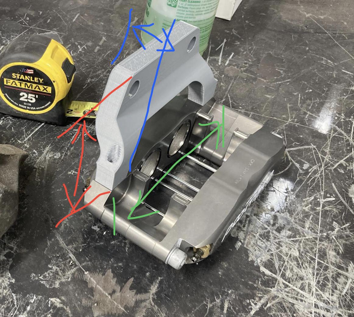
I only have my phone, so excuse my crappy edit. What are the red/green/blue dimensions aprox.?
I'll get you a whole model to play with if you want :)
54mm high (red) x 172 mm (green) x 36mm (blue). That's going to be fairly close.
In freedom units, that's roughly 2 1/8" x 6 3/4" x 1.5".
In reply to Keith Tanner :
Yes, please. 
I corrected the dimensions, I gave you the height of the one that was too high :) Model will be incoming soon, although there's a lot of fine-tuning to do before it gets turned into metal. If I get that spindle this week, that'll let me narrow it down quickly.
This version passes the eyeball test. It appears to put the caliper in the right ballpark.

A friendly Vanagon owner stopped by yesterday and left a spindle behind. Fitment tests can begin!
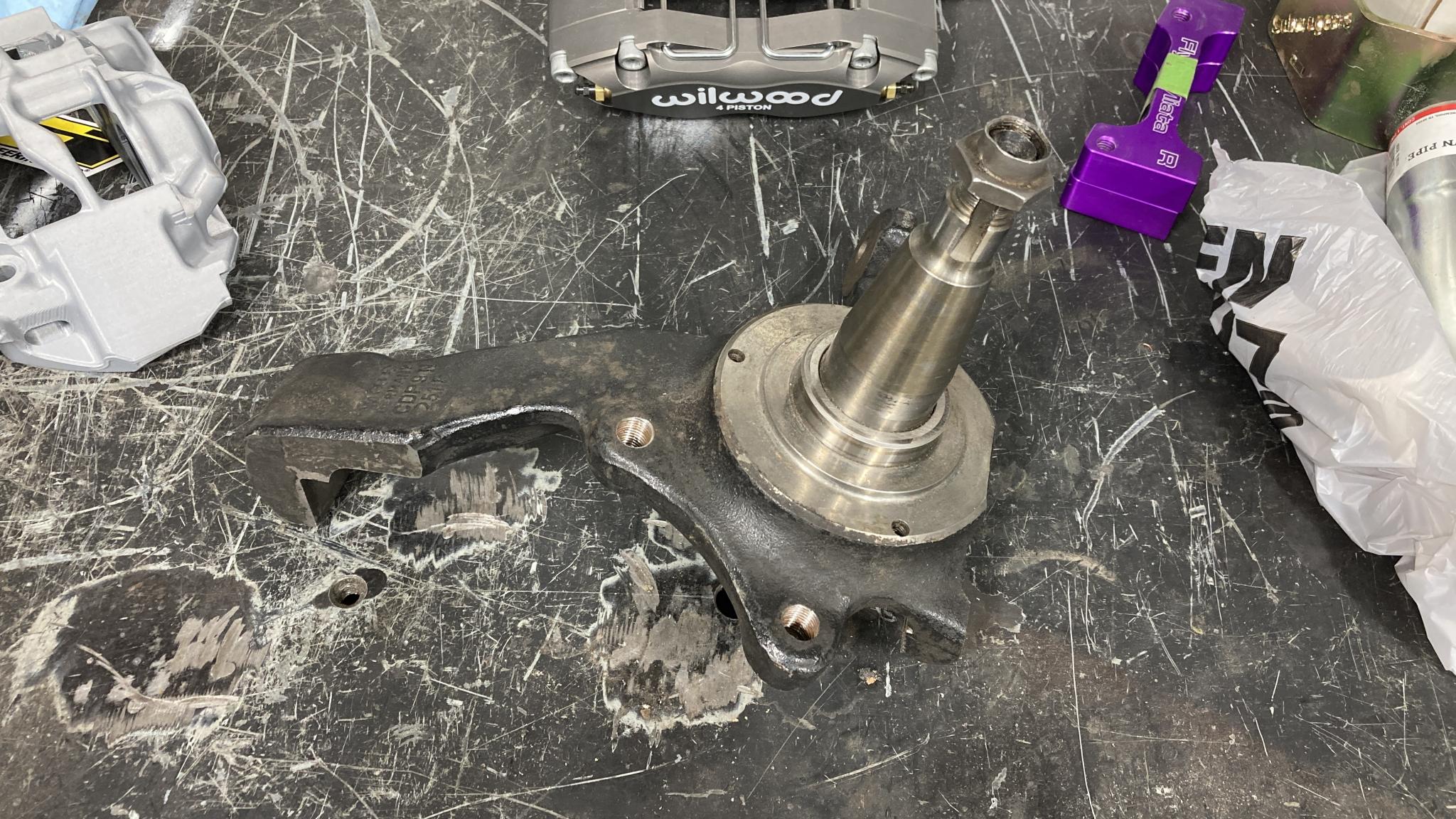
Well poop. I suspected this might happen. It's not just the bracket, the caliper makes contact.
Let's hear it for free CAD software and cheap 3D printers. Rotated the caliper 10 degrees around the center of the rotor (sure am glad I used that as the center of my model!) and this was on the print bed this morning. FYI, the equipment being used for this is a 10-year-old Macbook, Fusion360 and a $175 Ender 3 printer. This would have been a whole lot more difficult 20 years ago.
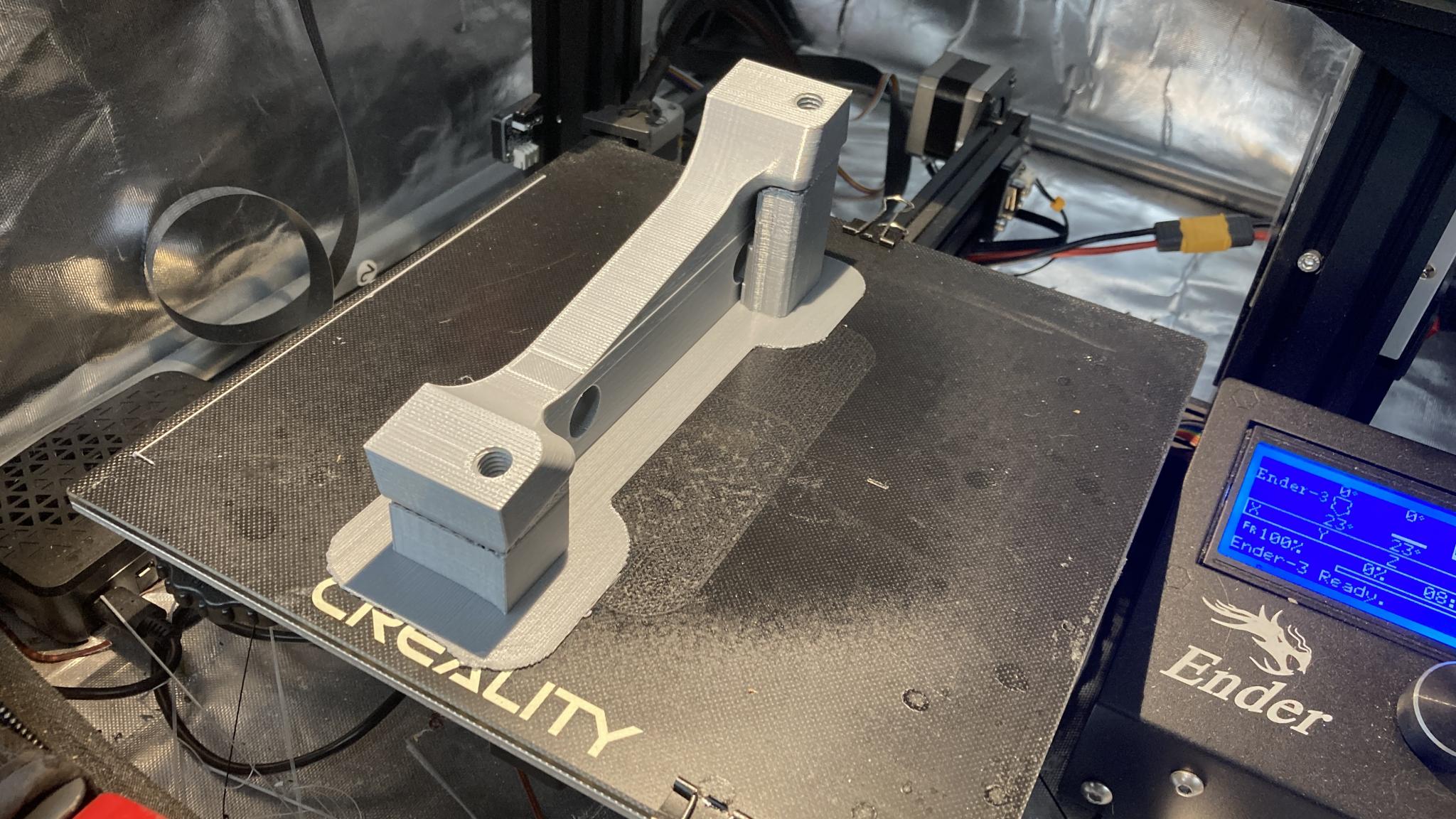
I printed threads into the bracket, but they work better if you chase them with a rethreading tool.
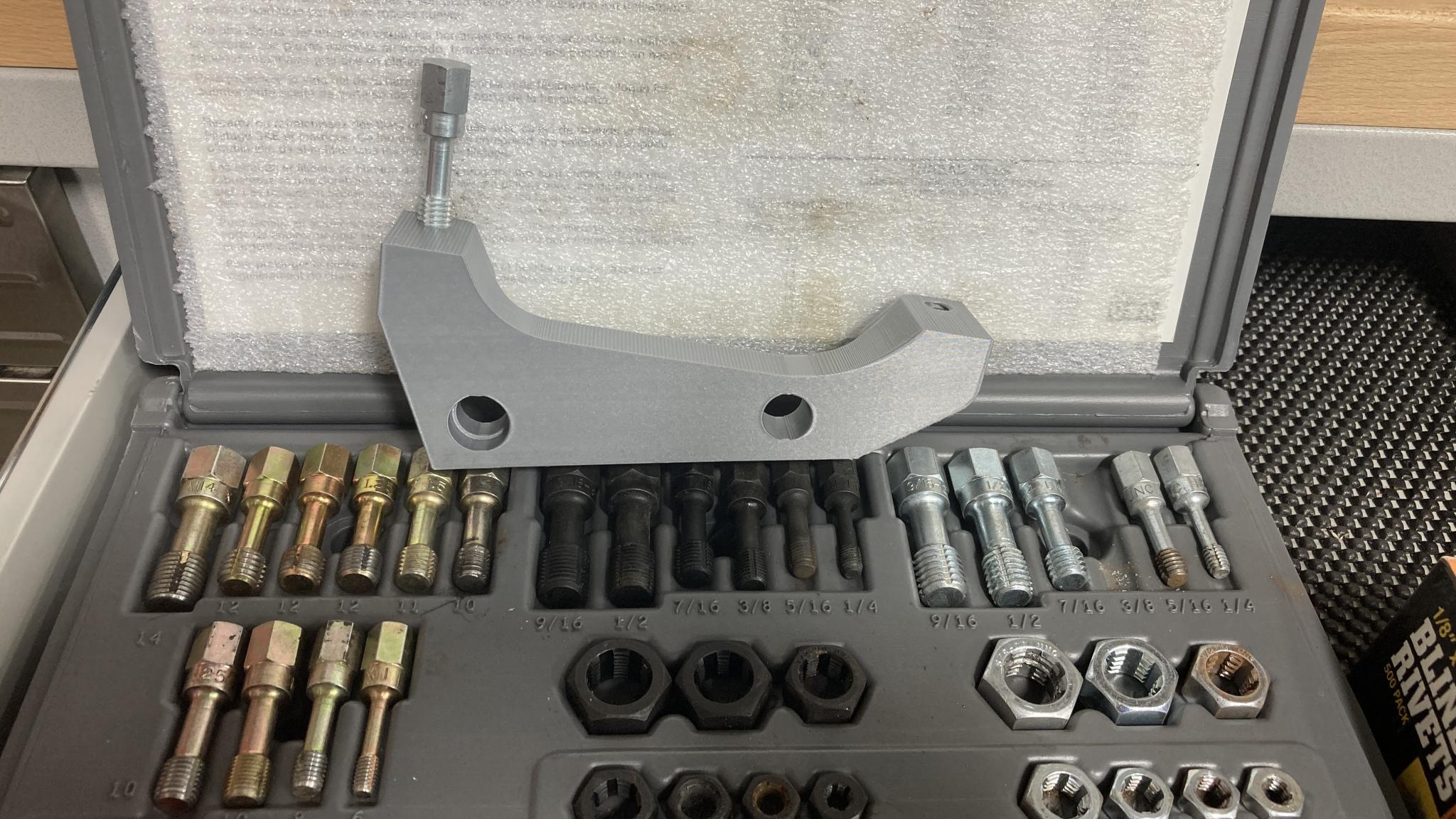
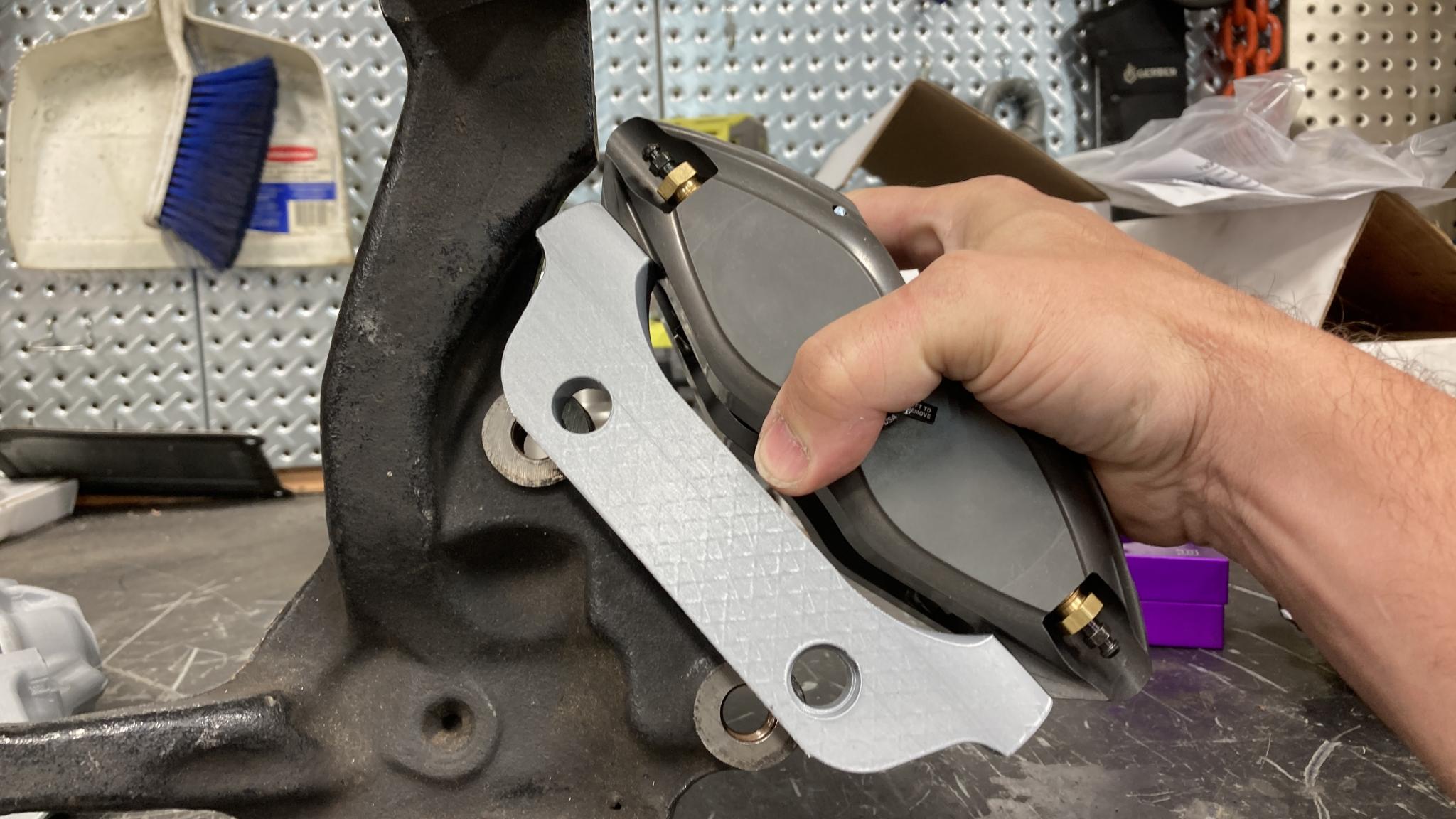
And voila. Nice fit!
Now I just have to put some wheel bearings into those rotors and make sure I got the caliper positioning correct. That won't be for a few days as I won't be in the shop over the weekend. But I want to see now!
One interesting thing I got from the friendly Vanagon spindle delivery person - apparently the later spindles that are used for all the cool brake kits are basically the same, but the caliper mounts on the outer side of the flange instead of the inner. You can machine the flange on an early van flat and down to 18mm thickness and thus bolt on the other big brake kits.
18mm is the offset from the mounting plane to my caliper bolt centerline (CORRECTION it is not, never mind) Does that mean this kit would work on a later Vanagon if you just switch the brackets side to side? Now THAT is interesting. Maybe not, it might not clear the rotor. But I'll take another look after this weekend.
In reply to AngryCorvair (Forum Supporter) :
The only two piece rotors I have played with had the rotors floating on the hub adaptor, so the rotors could expand radially with heat without pulling the cold hub outwards.
So they were not attached at all, in a fasteners under tension sense!
What is the stress on eight 1/4" bolts versus the two 12mm bolts holding the caliper on? Or the single stud at the ball joint...
I share your concerns, which is probably why everything I make is far overbuilt, but practice says it works just fine.
In reply to Pete. (l33t FS) :
Oh, c'mon. They are 5/16's ... no one in their right mind would use 1/4" bolts 
In reply to Keith Tanner :
Looking good.
One thing that I forgot to ask after looking at the model. Why does one of the bolt holes that attach the bracket to the spindle have a counterbore? Is there a pin that locates it?
Slippery got concerned that he'd built me a suicide machine as well and did some crude FEA. He came out comfortable with it, I'm not enough of a real engineer to be able to interpret everything he provided.
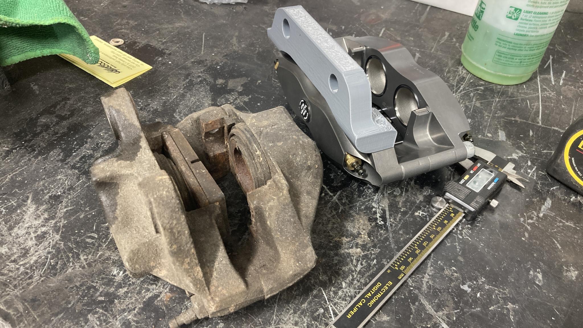
The rotor bolts are 5/16-18 Grade 8, for anyone who wants to do mathing. And yes, there are only two 3/8" bolts holding the caliper to the bracket. That's the biggest bolt that will go through the hole in the caliper. Again, I'm working off "this has worked for high horsepower Miatas on sticky tires and these are race calipers" for comfort level. I'll be sure to use good bolts, of course.
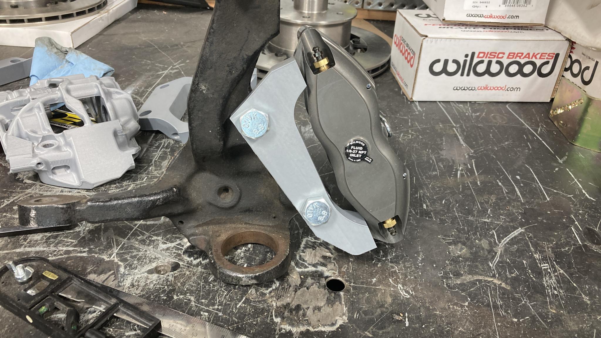
For those who want to visualize the stresses on my bracket, that's a right side spindle so the caliper is being pulled upwards in both the pictures above. Rotor goes clockwise in this pic.
Slippery said:
In reply to Keith Tanner :
Looking good.
One thing that I forgot to ask after looking at the model. Why does one of the bolt holes that attach the bracket to the spindle have a counterbore? Is there a pin that locates it?
IIRC one of the factory bolts has a shoulder on it. It's a feature that's on the stock calipers so I copied it. I'll take another look at my existing brake setup before I finalize the design but someone parked a CRX on my lift and took apart its brake system - it never ends. I'm going to use the factory caliper-to-spindle mounting bolts which are 14mm diameter in case anyone's still looking at this. The current hardware is just "hold this in place while I check that it fits" specification.
I'm not even sure I have the counterbore on the correct hole at the moment, I had to reverse my model when I discovered I was designing a left side bracket for a right side spindle :)
I appreciate the analysis that went in to this project. Brakes are the Wu-Tang Clan of car parts.
The project continues. This is an interesting counterpoint with how I did the first variation of this brake kit - this one's all being done with 3D design and a printer to check fitment.
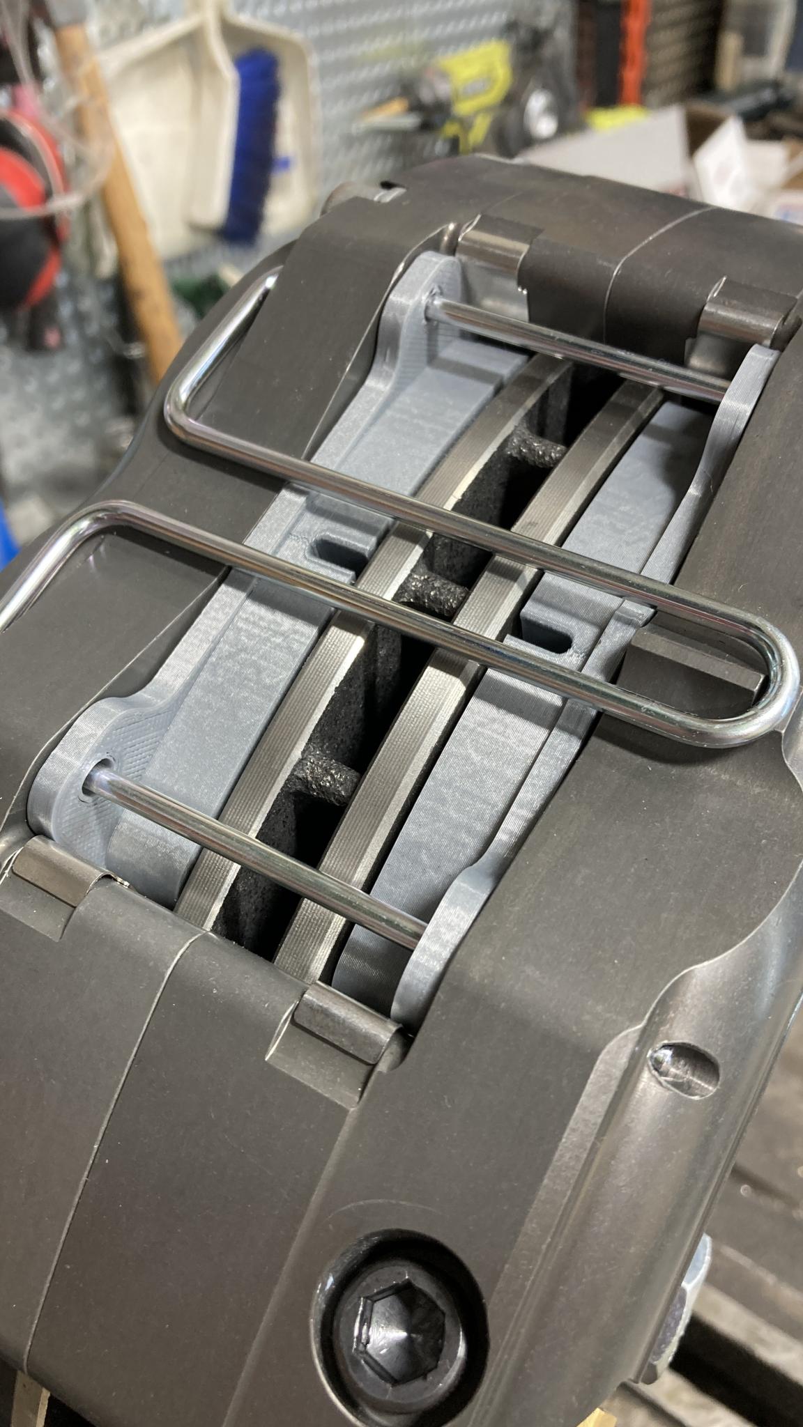
I pressed some bearing races into my new hubs and did some final fine-tuning of fit. But to truly check fit, I needed some brake pads. Problem, the only vehicle I own that uses these specific pads (Wilwood Dynapro 4-piston) is the VW, and it's using that set. So I printed some up from the model that Wilwood thoughtfully provided. There are so many trolling options here.
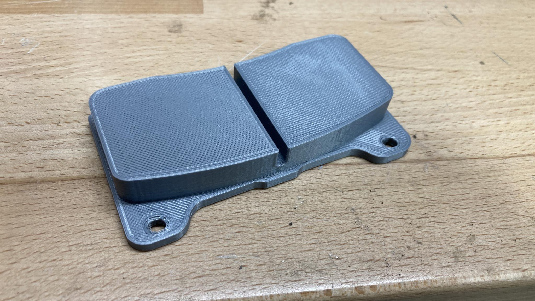
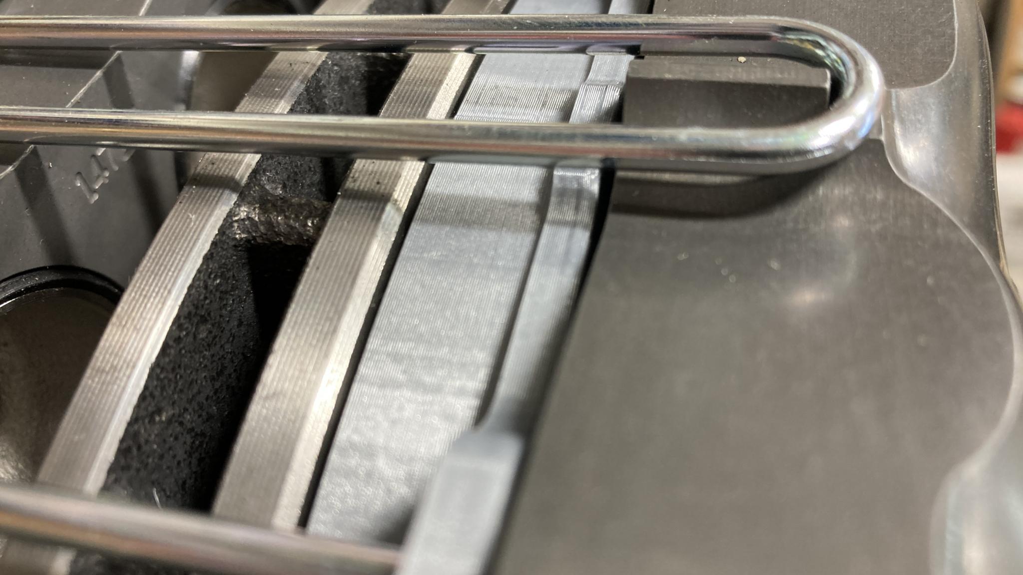
There's a chamfer on the rotor. I'd kinda like to have the pads level with the full surface of the rotor and not overlapping that chamfer, but I'm getting awfully close to rotor/caliper contact. The Wilwood mounting diagrams show the OD of the rotor should be level with the OD of the friction material, and that's right where I am. I'll do some measurements (this was quickly assembled with no time to do more checking) but I don't think I can move the caliper in by 1 mm, which is what would be required. Not the end of the world, it'll work fine.
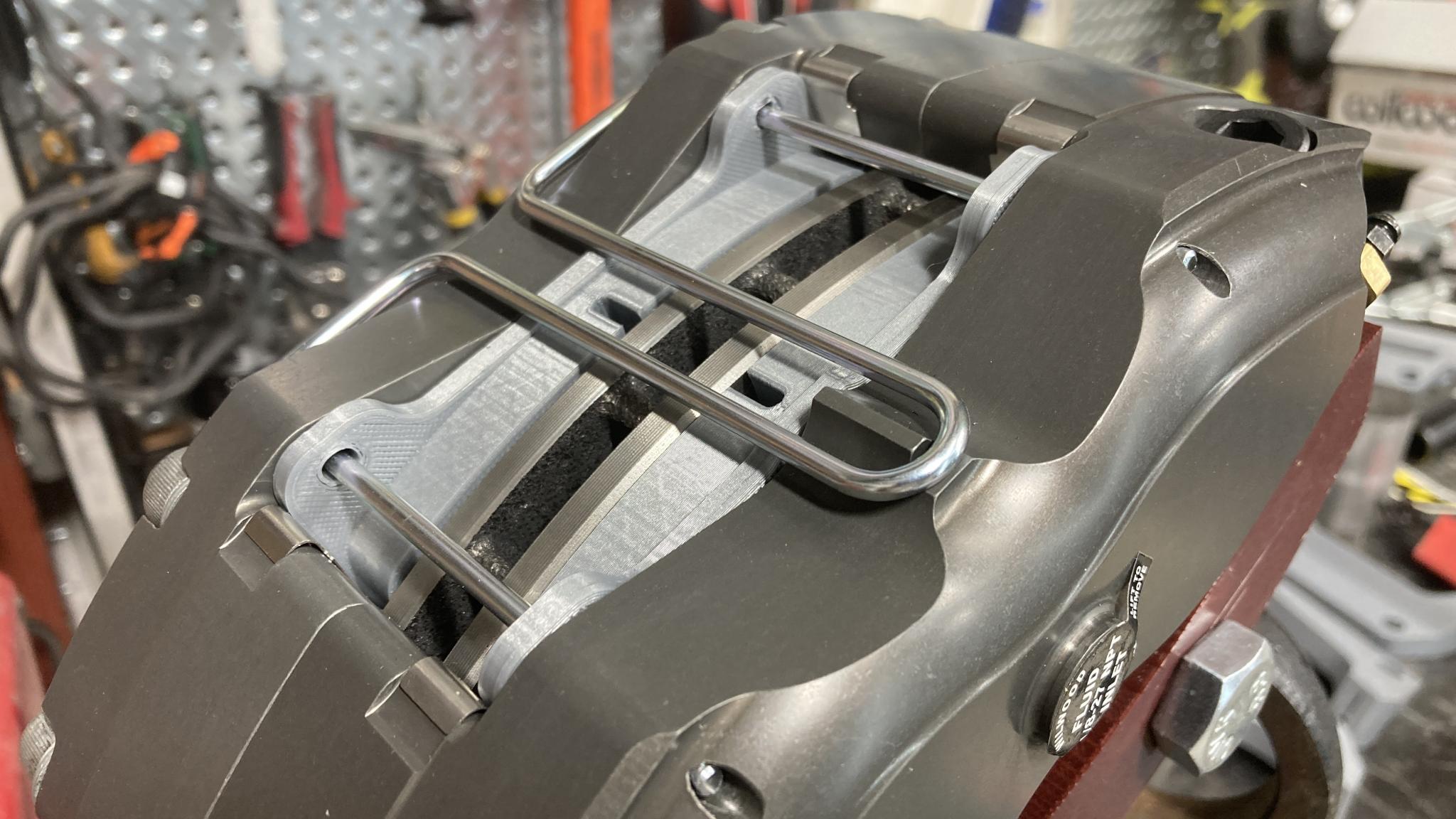
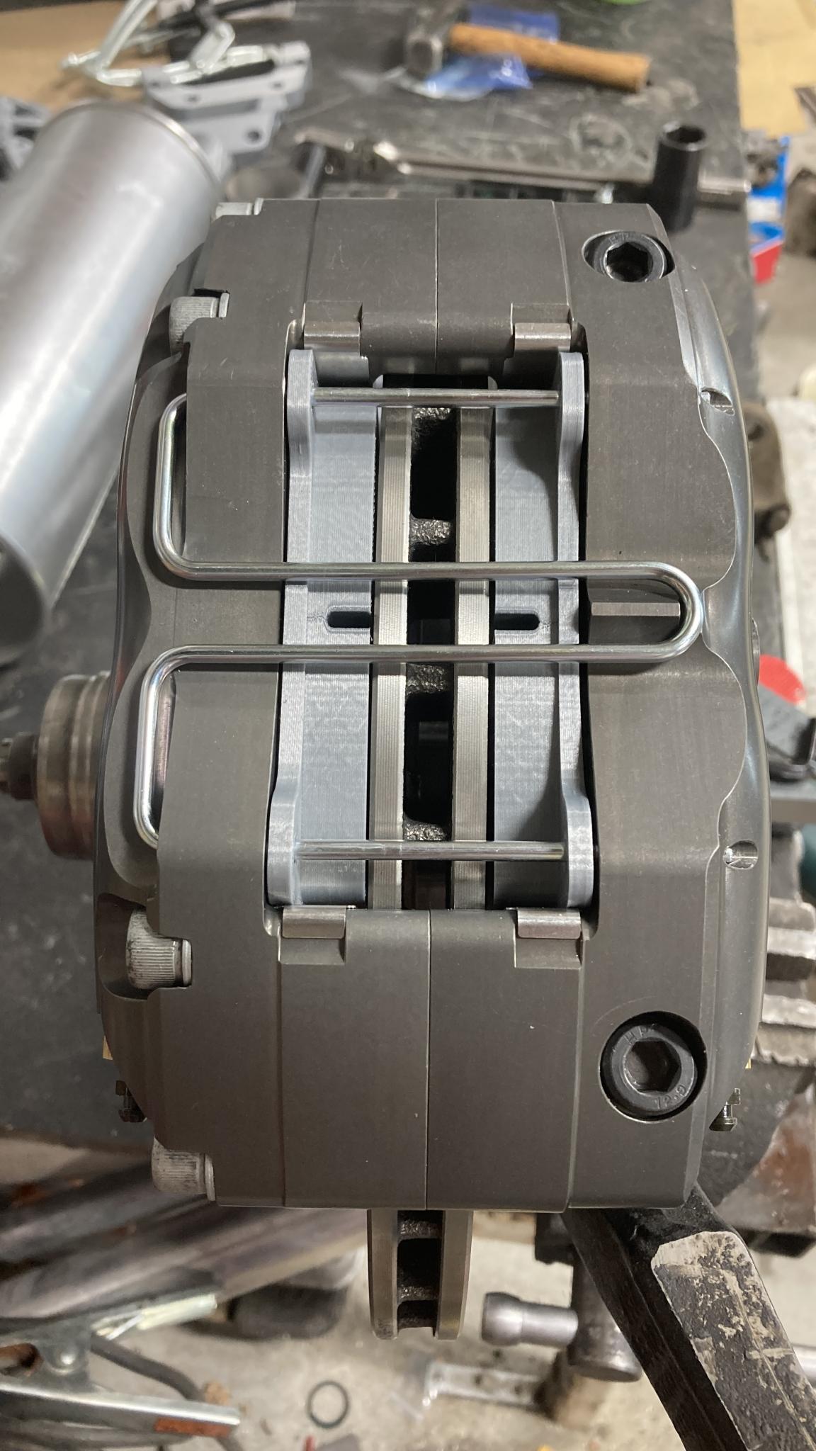
Lateral placement looks good. The rotor spins freely with no scuffing on the "pads".
I'll do some measurement checking to make sure the printed bracket matches the drawings and do a quick sanity check that I haven't forgotten something lurking in the wheel well, then it will be time to turn this into metal. We're getting close!
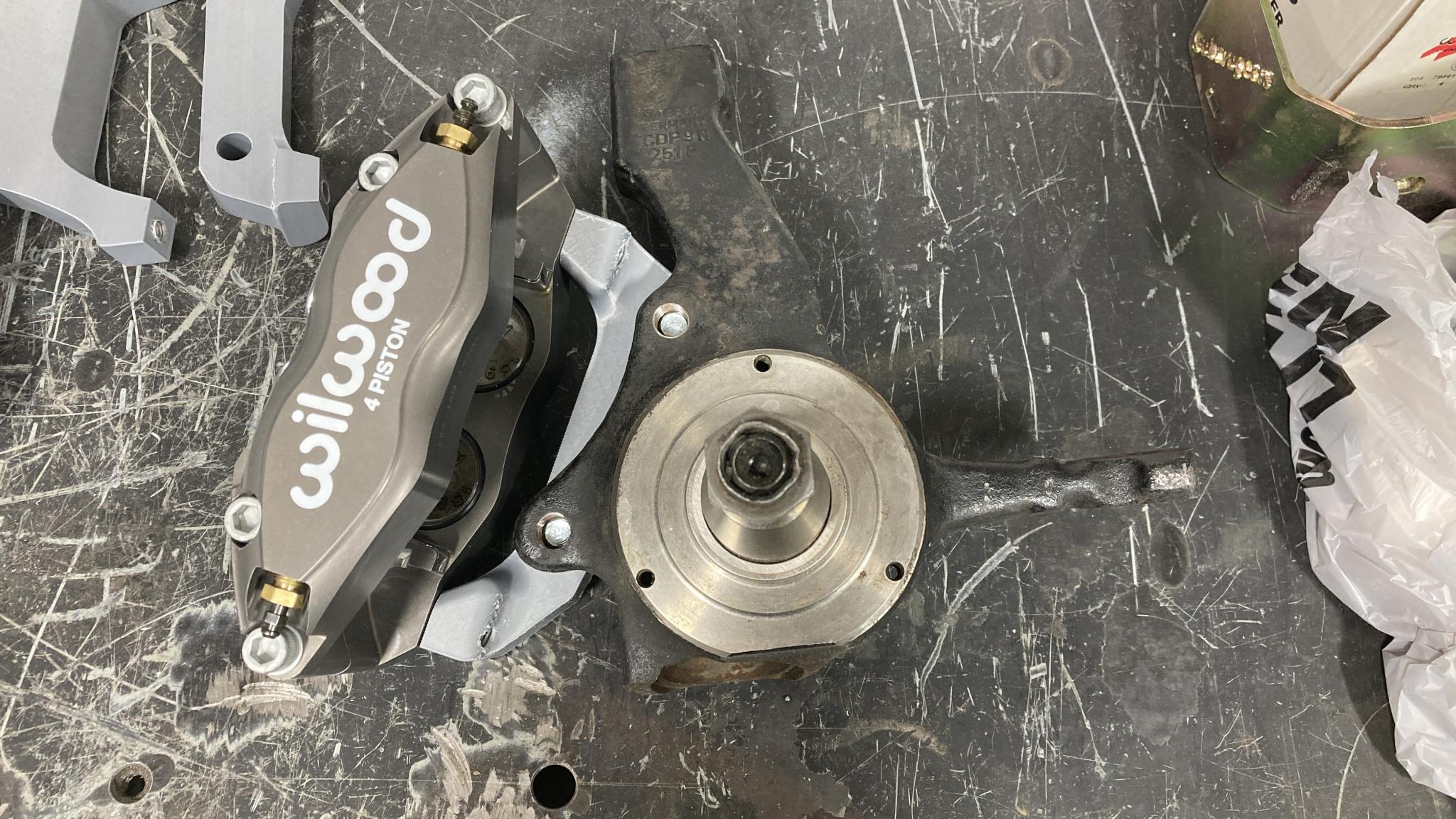
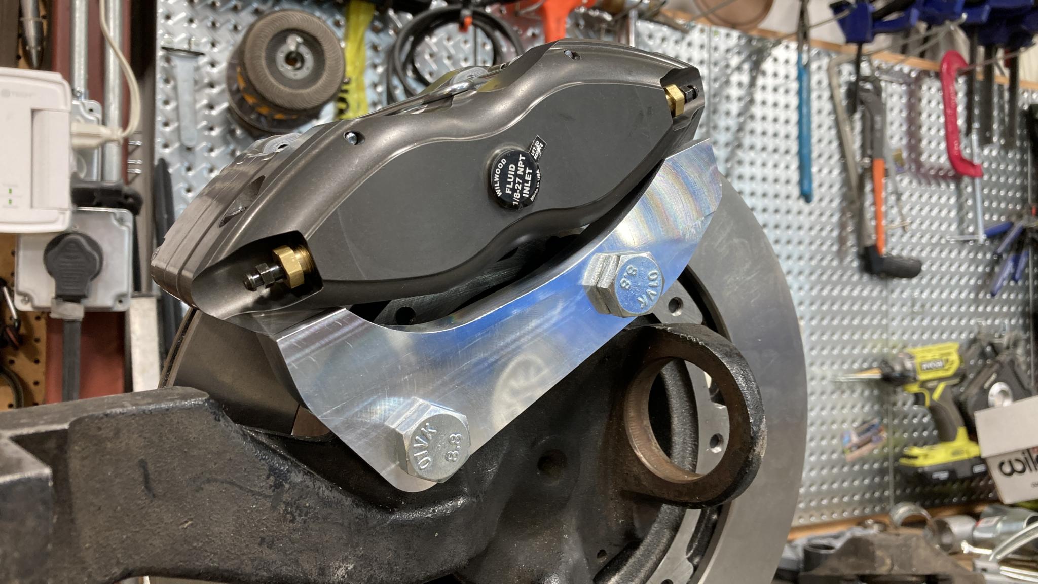
For those trying to visualize how this mounts, that big cast ring you can see is the bottom ball joint, so the top of the caliper is to the left of the picture.
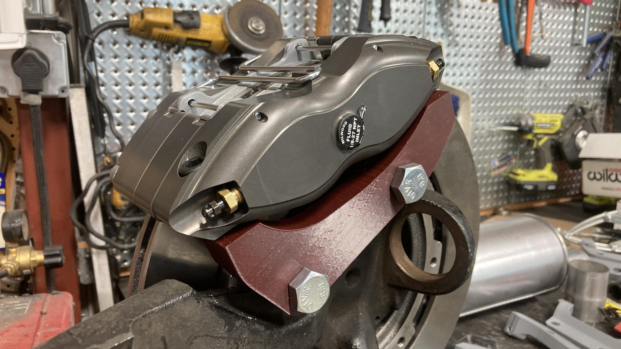
I pulled the van into the shop yesterday and did a test fit on a spindle on the car. Also checked the printed prototype for dimensional accuracy. It's all good to go. About the only thing that showed up is that the caliper could be rotated around 5 degrees closer to the original position. The current location may require a slight snip to a heat shield, maybe 1/2" or so. Of course, I don't recall if I'd modified that heat shield already. The current positioning also gives lots of room for bleeding, more than my first version that's on the van right now. So it will stay where it is.
I also pulled an actual brake pad from the van and used it to check the caliper location. Looks like I'm bang on. There's a bit of vertical movement available (a mm or so) in the printed pads that's less obvious in the real one. Also, the fit is very slightly looser in the real pad, when I measured my print it is 0.6mm too wide so it was just a little sticky in the caliper and didn't settle quite all the way in until I gave it a nice push. Here it is fully seated.
I could tweak on that bracket a bit to make it more aesthetically pleasing, but I think it's time to let it go and send the model to Slippery. To the best of my limited ability, it's going to be fairly easy to machine with only one change of setup required to make it on a vertical mill. Kinda hard to avoid that one change when the two sets of holes have to be in different planes. I could be wrong :)
I sent the models off to Slippery with the understanding that this was a "when I can get the chance" process. He got the machining done after a break for Real Life, sent me some sexy bracket pictures, and shipped them off. Whence the tracking for the package disappeared after it left Denver.
Nothin'. Until this afternoon, when I walked out the front door and a package was sitting there. The mystery is solved - a damaged box led to the disappearance of the barcode and thus the tracking, but a conscientious, anonymous USPS employee made sure the parts arrived!
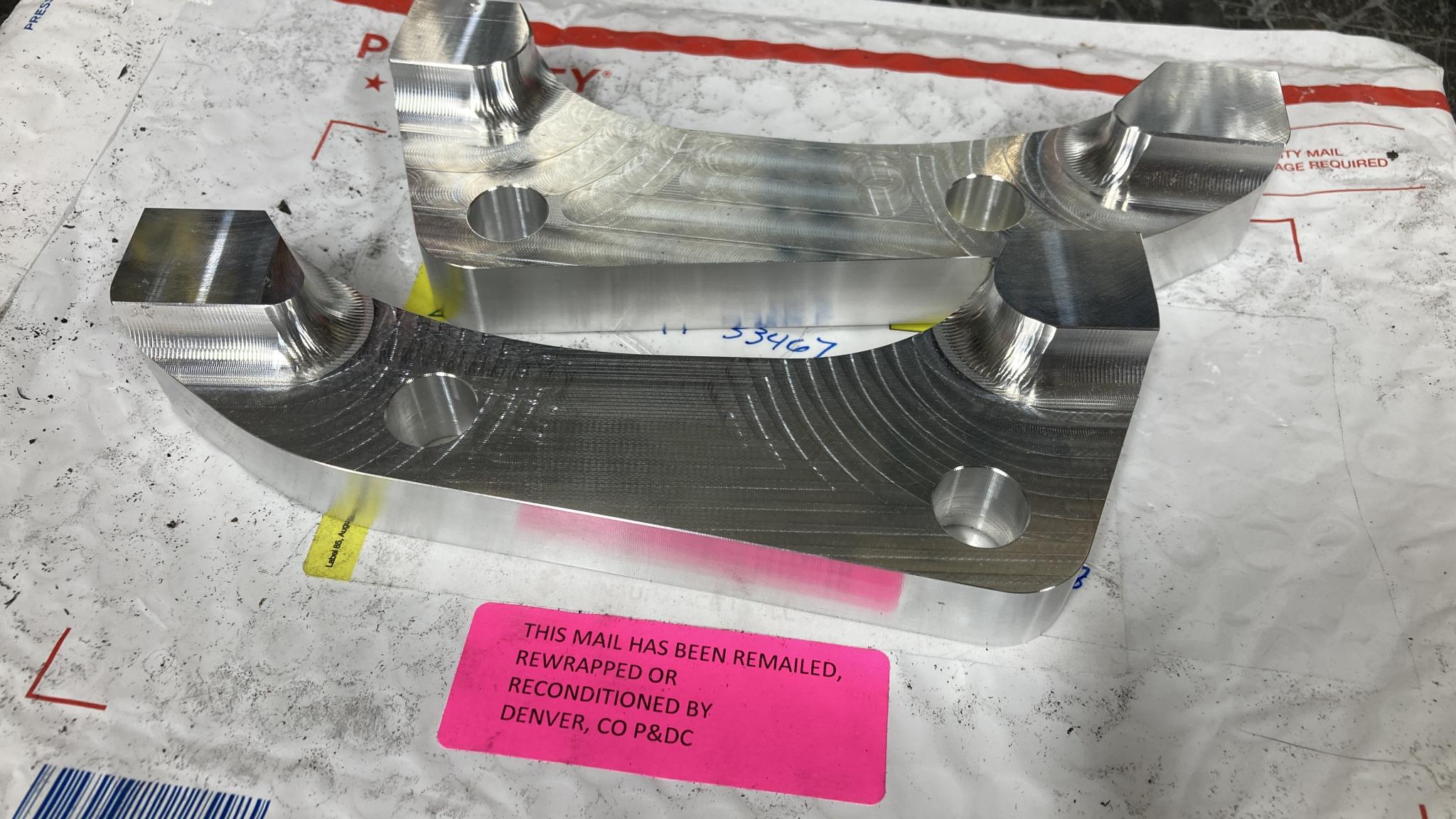
But more importantly, look at those sexy aluminum things. I have to say that even after checking my model with the 3D printer, I was more than a little nervous that I'd screwed something up. I mean, a screwed up print is no big deal but a screwed up machined bracket is. And since I'd been basing my model fine-tuning on those prints...gulp.
Test fit...good. All holes appear to be perfectly placed. I also have new hardware of the correct length for the application. I decided not to reuse the factory bolts because they're nearly 40 years old and I'm not sure where I put them :) The new ones are 8.8 grade because McMaster doesn't stock a 10.9 in a 14x1.5mm size. If my math is right, they each have a shear strength of nearly 16,000 lbf.
Test fit 2...perfect. The print of the model was accurate, and the model was accurate! We have a winner! Major props to Slippery for making this happen.
Now I just have to get the new hubs loaded up with bearings and bring the van in for the swap. It should be pretty quick to install.
Glad it all worked out and USPS finally delivered them!
Just make sure you use real pads and not those 3D printed ones!!!
I expect the PLA brake pads will have excellent material transfer and will work at their best from cold. Not recommended for track use.
In reply to Keith Tanner :
Now that sounds like a Garage 54 experiment.
Seeing the rapid prototyping here with the 3d printer is so cool. What a boon for you to be able to do so.
And slippery's machining is **chef's kiss**
I've mentioned it before, but the tools at my end are:
Macbook pro from 2012
Free subscription to Fusion360
$175 Ender3 printer
It's rather amazing. We have hit some sort of checkpoint for the future.
When I did the first version of this, I didn't have the printer and didn't feel like dealing with 3D modeling so I just fabricated with many reworks and fooling around. This was much easier and cleaner and I have more confidence in the end result. Plus, if we wanted, it would be straightforward to make more!
I would heartily recommend Dr. Slippery's Machine-While-U-Wait service :)
I'm sure that this has already been thought of, but what changes are being planned for the brake booster/fluid setup to go along with all of the shiny goodness?


