Got a decent couple hours in the garage tonight. AK1 sorted salvaged wires by color / tracer / diameter:

and I hacked up the C4 battery mount to fit an existing space. The starting point:

after cutting as close to level with mounting bosses as I could manage:

and temporarily bolted in, so I can figure out how to support the front of it:

C4 battery fits well. Location sucks for polar moment, but it's perfect for drag launch. Maybe it'll get relocated later. For now, good enough is.

Did a little CAD work on battery tray support last night:

and of course I got a dimension wrong, so it doesn't fit. V2 tonight.
checked measurements, adjusted template, transferred to scrap steel book shelf, trimmed and bent:

In free space:

And test-fit in its new home:

I'm not mad at that.
I need dimple dies. This part is screaming for a couple of 1-1/2" dimple-died holes.
In reply to Carl Heideman :
If somebody had my lawn edged because they thought the neighborhood looked unkempt, I would immediately fill my front yard with projects and let the grass grow for a couple of months... because I'm a spiteful bastard.
From whiskey-dick:

to wedding-dick:

thanks to a tech tip right here on GRM. I rounded the business end of an old chisel, supported the bracket with a block of wood, and gave it a few smacks. The bending stiffness is increased because the "dart" moves material into the plane that reacts the bending forces, like a wee shelf bracket. I think the formula is something like
bending stiffness = 1/12 * b * h^3
So increasing the amount of material in the "h" direction (perpendicular to the force the tab supports) makes a big difference.
edit: that might be a beam stiffness formula, I don't remember. Anyway, the concept is the same. If you want a support to be stiff, put material in the planes that react the applied forces.

A while back when the Aerodynamics sub was new, I started a thread about cooling this car. Since that time, I've made an almost-complete plan for cooling. Front-mount C4 rad with C4 fans:

Ducted to feed air from below front valence:

With a central air duct / console to provide combustion air to the engine and cooling air to the engine bay. Executing that plan affects a lot of other stuff, so I've been bouncing around between tasks as I try to integrate everything as logically as I can. The air duct impacts firewall shape, inlet air filter shape and location, shifter location, fuse block location, and wiring harness routing. Location of battery box impacts firewall shape. Exhaust config limits ECM packaging options. Etc.
In that other thread, Stafford1500 said
... header bags ...
which I assume aren't really bags, but I need to know more. I have a vision of HVAC ducts off the center console, directing air at the primary tubes, but not really surrounding them. I also have a decklid from an early Vair from which I will steal the louvers for MonZora.
and because I haven't shown any progress pix lately, just know that I'm still working on making sense of the wiring.

My brain was bouncing around between a bunch of topics tonight. Started with engine compartment close-outs and battery location:


then moved on to the center tunnel and how to separate combustion air from cooling air, and how to direct cooling air at headers. Artist's partial rendition:

I totally forgot how to draw in 3d.
I also kinda figured out where to package the C4 coolant reservoir. I know how high and how far to the side. Still gotta figure out the fore/aft.
You're a budding MC Escher with that sketch. Double-reverse perspective!

OjaiM5
HalfDork
8/12/22 5:53 p.m.
I like the drawing it is really good! Just remember that your two vanishing points will be on the same horizon
In reply to OjaiM5 :
I don't think I ever knew that. I was trying to have the one on the right a good bit higher than the left. I was sitting on the floor next to the car trying to draw what I saw and it just wasn't working. Then I remembered 10th grade art class and the vanishing point idea. Even with the right side VP much higher than the left, it really helped a lot.
Had to install the passenger seat so I could plot out the dimensions of the central air duct:

bought a 20' stick of 3/4" x 18ga square tube to start mocking up the firewall and engine cover, and started taking dimensions and rethinking a couple details of how it's going to go together and come apart:

also trying to figure out how to package the C5 air filter, since I already have it. I think it's just too dang big, which leads me to a question I have not yet googled: what's the formula for engine air filter area vs engine size and RPM?
AngryCorvair (Forum Supporter) said:
...which leads me to a question I have not yet googled: what's the formula for engine air filter area vs engine size and RPM?
Buy whichever one fits the space you have available. Seriously.
My drag'n'drive buddy uses a tiny K&N meant for a 1.0L Peugeot, or some other equally ridiculous thing, in a polycarb scoop. N/A small block car that was running 8.90's at the time; forgot to pull the filter and still ran a 9.06
Roof snorkel. Definitely roof snorkel.

Crude dimple die idea if it's not worth investing in a set because you won't use them enough.
In this case I used a handle for a large threading die as the outer diameter of the dimple with some masking tape on it to protect the side to be seen when part was installed and keep the handle in one position. An impact socket for the small diameter with a piece of aluminum to beat on so I wouldn't be banging directly on the socket. And then used a BFH as a persuasion device (press is optional). Some metal bumping may be required to form the panel or flatten it after dimpling depending on size and depth of dimple. And yes, I sand blasted the piece before installation & epoxy primer.
[URL=https://app.photobucket.com/u/NOTATA/a/6b6f76c0-5830-42f9-94b2-3399d5fddd0f/p/f071c12b-c542-41f7-a7f9-183b5abc4268]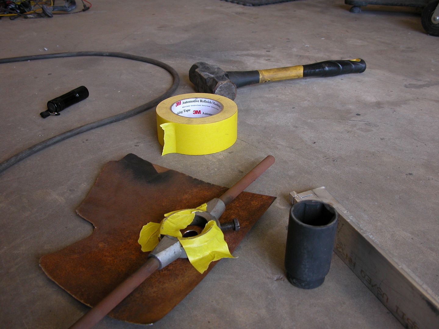 [/URL]
[URL=https://app.photobucket.com/u/NOTATA/a/6b6f76c0-5830-42f9-94b2-3399d5fddd0f/p/383ca23d-d3ae-45b3-a24d-2e11f0d8a308]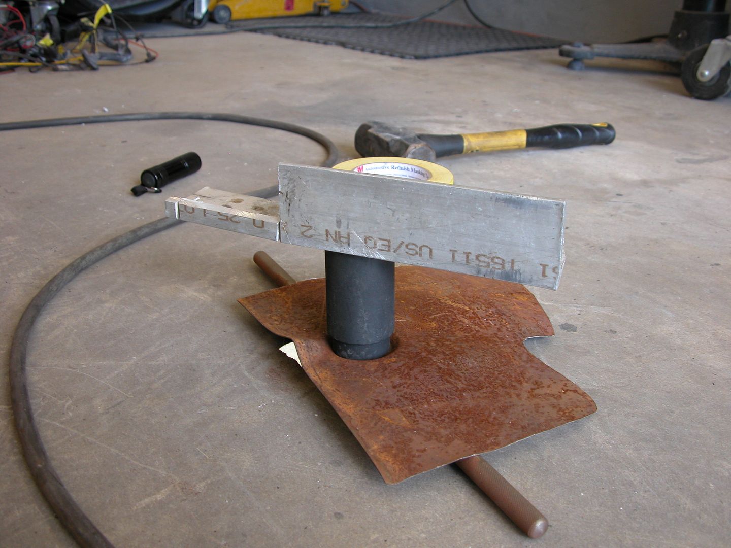 [/URL]
[URL=https://app.photobucket.com/u/NOTATA/a/6b6f76c0-5830-42f9-94b2-3399d5fddd0f/p/36f26aa3-c366-40ac-a8e2-24fc2f68d5fd] [/URL]
[URL=https://app.photobucket.com/u/NOTATA/a/6b6f76c0-5830-42f9-94b2-3399d5fddd0f/p/f90e43f5-2e2a-4a92-9a71-7058c291e1c7] [/URL]
Have you considered mounting the air intake under the floor rather than all the way up front? I wouldn't expect you''ll be fording rivers.
Also IIRC you can get a smooth rubber piece in the HD plumbing section to replace the corrugated one that weighs less and has better flow.
NOT A TA said:
Have you considered mounting the air intake under the floor rather than all the way up front?
No, I hadn't. But now you've got me thinking that I might be setting myself up with inlet air deficiency at the starting line. The cross-section of my duct is 3x the area of my throttle blades, so I was thinking I shouldn't see any restriction.
Also IIRC you can get a smooth rubber piece in the HD plumbing section to replace the corrugated one that weighs less and has better flow.
I will look into that, thanks!
I spent a lot of time thinking today before I got into my CAD work. I didn't figure out every detail of the engine box, but I did figure out a lot of it. I started with the front panel, which will hide the coolant hoses and separate cooling air from combustion air:

with the seats at maximum rear travel, and as reclined as C4 seats can go, there's still a gap to this panel:

From there, I stood and stared from every angle, trying to decide where to go next and how to get there. So I went out and started measuring the bookshelves and filing cabinets I've scrounged for this job, and I realized that the shelves have mounting flanges already built in! I will have to do a good bit of cut and paste, but it's gonna work out really well. So I made a template, took some dimensions, and laid out my cut lines on a shelf:

I allowed about 1/2" overlap so I can drill one panel and rosette them together. They're currently held in place with a clamp and a couple of magnets.

the plywood under the battery is just there to protect their package space. With the shelf flanges facing away from the engine, I can join the panels with sheetmetal screws or, if I'm feeling really special, riv-nuts. Also, the flanges provide a good space for sound and heat insulation. This car is going to be a lot nicer to drive than the Crown conversion I ran 20 years ago.
I really hope I can be there when this thing runs at challenge. Pretty sure I'll be able to save enough for the trip by 2027. Still, I can criticize the pace but I can't criticize the work. Keep it up.
Any chance the intake could be installed 180*? Putting the throttle body on the back?
i doubt it...
so what about just running a 90* bend to the right and taking air from a hole you'd cut in the door or from the rear fender??
jfryjfry said:
Any chance the intake could be installed 180*? Putting the throttle body on the back?
i doubt it...
so what about just running a 90* bend to the right and taking air from a hole you'd cut in the door or from the rear fender??
I wondered about this option as well having done it before. Not sure if it can be done on all LS though.
[URL=https://app.photobucket.com/u/NOTATA/a/9431e992-e7d7-4375-ab32-667aefbfe51c/p/8d1bce53-f282-4318-9c3f-a5e9ec62935a]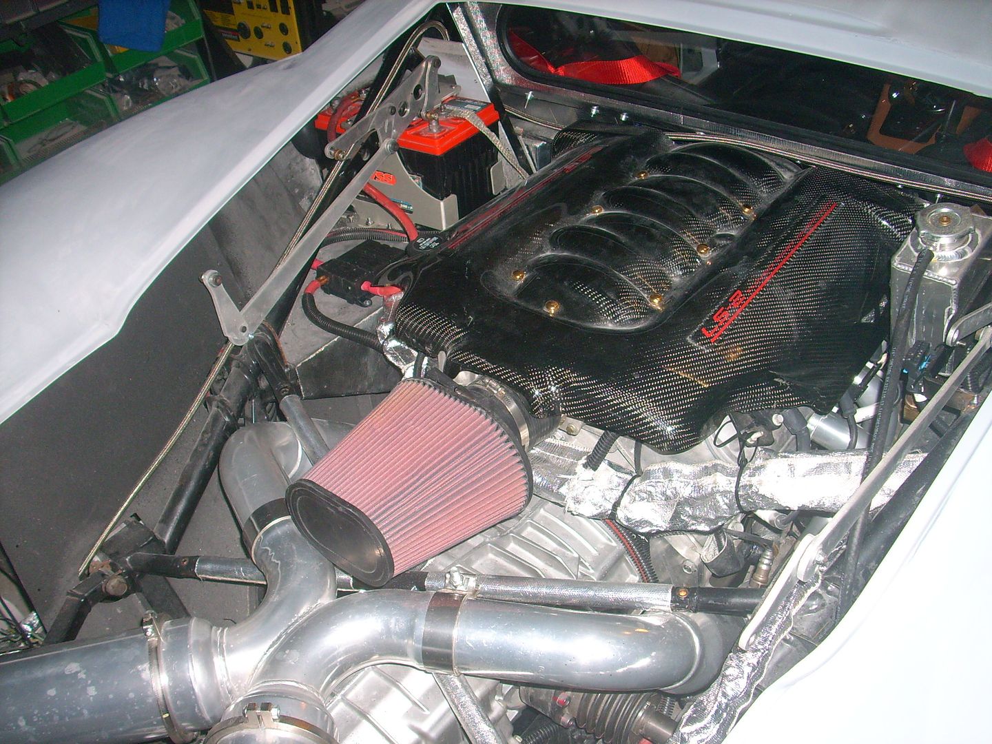 [/URL]
In reply to jfryjfry and NOT A TA :
nope, not possible without major fab work on the LT1. also, not cutting holes in the outer body.

wawazat
SuperDork
8/15/22 1:21 p.m.
Backwards S shape from throttle body up to inner roof mounted air filter housing with intake holes or NACA duct in plastic rear window?
wawazat
SuperDork
8/15/22 1:22 p.m.
Oh-make it a Z shape for Zora!
Is the air filter not allowed to just be right there on the throttle body between the seats? Otherwise I like the idea of a 90deg turn to the passenger or driver side. Factory air box housed in that same compartment as the battery or something.
In reply to maschinenbau :
I imagine a speaker grill between the seats that emits the most glorious sounds.
Though sealing it as part of a firewall will be challenging but not impossible. Backfires would be exciting..


