


If I'm underway and the throttle somehow pins open (which can happen with a 15' long 35 year old mechanical cable as well)
reply to Keith Tanner :
I have had this happen in a 911 with mechanical linkage. Your drive by wire sounds brilliant.

If I'm underway and the throttle somehow pins open (which can happen with a 15' long 35 year old mechanical cable as well)
reply to Keith Tanner :
I have had this happen in a 911 with mechanical linkage. Your drive by wire sounds brilliant.
another thought...
you can have a proteus board printed by JLC and only populate the board with the Chips needed for the ETB and the Pedal...
its all open source, so you can " manufacture" it yourself...
that way the hardware will be all set up for you, and the software would be just a matter of running the Autotune on the ETB
and the Pedal.
my memory is ... you would only need the black 23 pin connector (ETB)... and the White 35 pin connector (Pedal ) ... so you can leave off the black 35 pin connector... save money that way...

From what little I've read, CAN is generally considered not fault-tolerant enough or real-time enough for drive-by-wire applications. I find this strange, because in aircraft we're perfectly happy to put autopilots and their servos on a CAN bus... with a ton of other devices. So I'm sure it could work fine, but it'd be interesting to know if the typical CAN bus implementation we use on aircraft is significantly different from the automotive implementations? It does seem like aircraft are going to be a lot more tolerant of laggy control input than a car, but it looks like even a heavy loaded CAN bus ought to be responsive enough for the few bits of data you need to send for throttle position requests. I guess what you really care about is the worst-case scenario with network collisions, and it may be the case that's non-deterministic with CAN?

billstewartx, I think you're overestimating my need to invent this right down to the circuit board. I'm happy using off-the-shelf microprocessors with integrated power management and easy-to-access GPIOs.
Berck, that's an interesting point. I've seen dynamic stability control systems running on high speed CAN, with enough fault checking to tell if you've put a gateway in the system that reads and forwards the messages. It seems that a throttle position on a 160-ish hp engine would be just fine as real-time. But you're right that every system I've worked with has tied the pedal directly to the ECU, which then puts the TPS out on the network in case anyone else wants it. The GM PCMs transmit it every 12.5 ms, which seems fast enough for my purposes. I'll post some interesting info from the GM docs in another post.
Since it would be a dedicated bus just for one-way communication of the requested throttle position, collisions are unlikely to be an issue but I'd have to do some sort of error checking to make sure it hadn't been too long since the last message arrived - meaning a broken CAN circuit.
The CAN hardware architecture would be to have one microcontroller (an Adafruit Feather M4, which is what's running the dashboard in my track car) at the pedal reading the two sensors and determining the requested position. That would be sent via CAN to a second microcontroller which would command the position using closed loop control from the two sensors in the throttle body. Right now, I have a single Feather RP2040 doing both jobs and its cycle time is faster than its ability to send readouts to a terminal. Alternately, the pedal controller could simply broadcast the value of each of the throttle sensors, and comparing that information at the throttle body controller would add in a bit of error checking. That's probably a better choice.
The overall advantage is that only two wires would have to run the length of the van and it's easier to protect digital signals from interference than a pair of 0-3v analog signals. Plus it would allow me to use some of my CAN chops and learn what I don't know :) It would also allow for more flexibility in the future for other weird applications, a pedal module and a module that knows what to do with it.
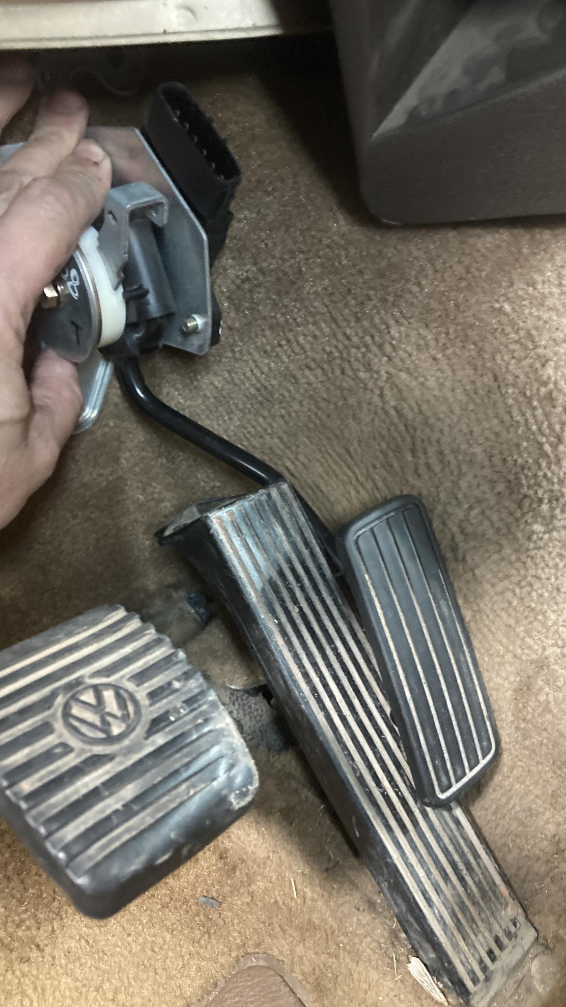
I did take the chance to test-fit the pedal today while working on the transmission swap. I think it's going to work well as-is, but if it doesn't there are some good modification options with the steel arm on the pedal.
For those who are interested, here's some info on what GM specifies for the broadcast throttle position in GMW8762.
4.2.3.250.1 Powertrain Interface Definition. Throttle Position is transmitted by the Powertrain ECM. It represents a throttle position sensor interpretation, after scaling, zeroing, diagnosis, and failsofting and does include cruise control effects.
0% shall represent the near closed bore position at which the engine will often stall. An idle or coast or 0% Driver Intent state will be represented by a value between 0.5% and 20 to 40% depending upon engine temperature (fast idle) and application (throttle body design criteria). 100% shall represent full available power airflow, but full available power may or may not be provided.
This parameter will reflect all controls and functions, which use the throttle as an actuator: This parameter can significantly vary during a shift without the driver or cruise requesting a change:
Driver intent functions (e.g., driver depressing the accelerator pedal, mode switches, and other parameters as well as filtering, cruise control).
If driver intent is interpreted to be an acceleration or axle torque request, then this parameter shall include the functions (e.g., mass, gear ratio) required to produce the desired axle torque or acceleration.
Any control function requesting the opening or closing of the throttle to increase/decrease engine output torque (e.g., traction control, drag control, all torque management, vehicle speed governing/limiting and engine speed governing/limiting).
Throttle adjustment for engine combustion efficiency torque losses (e.g., due to EGR, Air-fuel ratio, and certain spark retards).
Throttle adjustment to compensate for engine, transmission or vehicle friction, accessory loads, and torque swaps (e.g., gear losses, idle friction, a/c compensation, individual cylinder deactivation/shutoff).
Throttle adjustment to compensate for air density (e.g., altitude, temperature).
In all cases:
It is not an indication of actual power or acceleration.
It does not include the effects of spark retard or cylinder shutoff or other non-throttle control torque reductions.
Powertrain shall capture and then calculate this parameter at a nominal rate between 10 and 20 ms with a variation of ±2.5% and transmit every new calculation and only new calculations at the same capture/calculation rate ± 20%. By doing such, receivers of this parameter can calculate the rate of change of this parameter with an accuracy of ± 2.5%. The actual nominal rate must be defined in supplier specific section. Need to determine acceptable variation. This 5% value is a guess.
This parameter will always represent the actual throttle output of the engine during failure mode operation. This is a result of the security strategy to limit driver intent (and resulting actual torque) to approximately 0 to 20 to 40% throttle position, depending on application.
When both of the throttle sensors fail, the ETC system will disable the throttle motor and the actual Throttle Position will be between 20 and 40%, depending upon application and some part-to-part tolerance. At the same time ETC will cause torque management to reduce the torque to that desired by the ETC system based upon other inputs. Usually, the torque will vary with the accelerator Pedal Position between idle (Pedal = 0%) and the Maximum Authority (approximately 88 km/h (55 mph) steady state road load). When this is occurring, this parameter is failsofted to the throttle position that would provide the maximum torque as the ETC torque management system is providing. It will vary between approximately 0% and 20% to 40% throttle position, depending on application. Since this parameter still represents throttle fairly accurately, Throttle Actual Position Validity = “Valid” and Reduced Power Indication On is “True”. Cruise control, traction control and drag control are disabled. Any functions (such as kickdown shifts) that still require a 0 to 100% driver intent accelerator pedal position indication will not operate properly and must look at Accelerator Actual Position.
clownkiller said:If I'm underway and the throttle somehow pins open (which can happen with a 15' long 35 year old mechanical cable as well)
reply to Keith Tanner :
I have had this happen in a 911 with mechanical linkage. Your drive by wire sounds brilliant.
My favorite failure mode of a mechanical linkage involves broken motor mounts. Things can get weird.
If it's a dedicated CAN bus, I think you have exactly nothing to worry about. The link-lost failsafe is probably reasonable (I'd make it a value that's huge for a computer but small for a human (something like 0.5s) because you really don't want to ever trip over it), but as you've pointed out, a stuck throttle in this thing is unlikely to be a major issue. I was also going to say that no one requires redundancy for a throttle cable, but I remembered my Vee is required to have 2 throttle return springs:)
Compared to dual analog signals, I'd guess the CAN bus with digital signals and failsafes is probably a cleaner more-reliable option. Not that the 0-3V across 15' is a bad solution either. Theoretically, the throttle response is slower, but practically I think that's a non-issue:)
Thinking a bit more about the aircraft thing--in the aircraft that I know that move autopilot data over CAN bus, the failsafe is rods and cables from the human to the control surfaces. You don't have that in DBW application--but you're also just talking about throttle input. I think I'd feel a lot differently about this if you were putting steering or braking data over CAN.
I wandered down the CAN-based path last night. Got it coded up, soldered up a little interface for the new pedal, added a little special sauce...and then it kept throwing errors. One sensor was pinned open while the other was reporting 0.
Finally, after much checking and rechecking of wiring diagrams and tests of pins, I came to the conclusion that the throttle pedal had some bad sensors in it. This was the pedal I'd chosen as my ideal one, so that was a little frustrating. Luckily, beside the one that clownkiller had provided, I had a spare that I'd purchased on eBay from Lithuania (!). Man, if only we had functional pick and pulls around here, this would be a lot easier. I tested the Lithuanian pedal and it was good. Did I kill the other one somehow? Had the car gone to the junkyard with a bum pedal? Who knows.
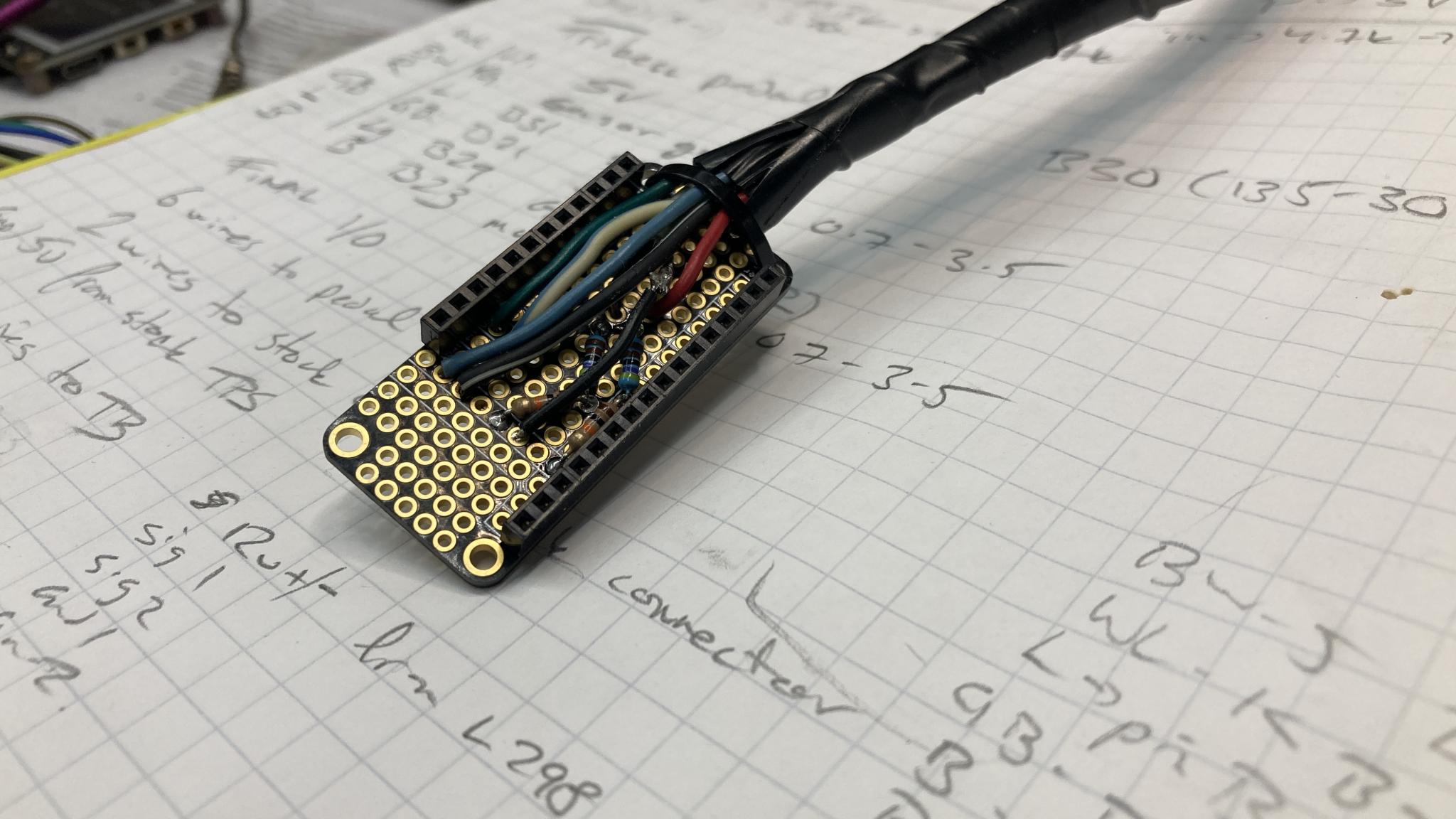
Here's the little interface. I'm building these in the "Feather" footprint from Adafruit. It's a couple of dollars more than trying to engineer the whole PCB from scratch (maybe not at these volumes) but it's nice and flexible and modular.
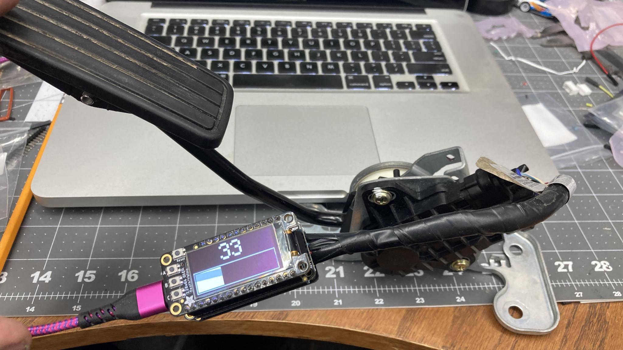
The pedal microcontroller. This is checking the sensors in the pedal and converting them to CAN signals. At the moment, it's sending the average of the two but I might change it to send both. That will act as a secondary check against a transmission problem. I also added the small screen to make troubleshooting easier when it's in the van - in early days, if I have a failure, I can check to see which of the microcontrollers is having a problem. I expect I won't need them forever, in which case I'll just pop the displays off and use them somewhere else. But it sure makes testing easy.

Very nice project!
Wouldn't it make sense to include the possibility of adding a cruise control with clutch and brake switches, and running enough wires from the pedal controller to the Throttle controller to have the option in the future?
Since the two controllers are going to be communicating by CAN, I have all the wires I need. If I wanted to add something like cruise, I'd just have to add inputs to the pedal controller and send data via the network.
I'm really liking the CAN setup if only for the modular aspect. It makes the wiring much neater if only because I just got rid of four extra wires that need to feed into the throttle controller. But it also makes the logical breakdown of the process more obvious.
Still playing with this :) I built a CAN receiver for the throttle plate and added a screen to it as well. I've got it working pretty well most of the time, with the occasional excursion into a flapping throttle pedal as the control loop loses the plot on very slow throttle movements. It also doesn't quite perfectly reach the target throttle position much of the time, so I started to think about adding a time factor and realized I was gradually reinventing PID as discussed earlier. So I grabbed an open source PID controller and started playing with that. Better, although I've still got some experimentation to do in order to get the behavior I want. This is fun.

FWIW, the first generation of GM drive by wire had a separate throttle module that communicated via CAN with the PCM.
It has been a short while but I believe the TAC handled the inputs/outputs from the accelerator pedal and throttle body, but the PCM did most of the work of telling the TAC what to do.
Oh, interesting. I used the (current) GM CAN messages, I might have to see if my pedal will actually communicate with an early GM pedal. Any idea what the year range is?
I realized this morning I need to add a timer to the CAN receiver so it goes into error mode and closes the throttle if it's been too long since a message has arrived. Easy enough but important.

Keith Tanner said:
I've adopted this 'screen-on-everything' idea. Both the parking brake module and TCM spoofer I'm working on I added them. So much easier to verify functionality. Plus, even though it's hidden it's cool so sometimes see "Parking Brake: Engaged" or "Gear: 3 Park Engaged: No"
I think those TAC modules were all on the first DBW LS stuff. Still Gen3 though. Like mid-late 00's? The blue/green PCMs?
In reply to Keith Tanner :
Could not tell you a specific year range, but it was the 24x crank signal era. When GM went from a PCM to a separate ECM and TCM at about the same time they switched to 58x, they made the drive by wire controls internal and not on a TAC.
Of course there are outliers, I think one year of GTO was a mishmash. I think another rule of thumb is three bolt throttle bodies with two connectors used a TAC.
Spent some time playing with the PID settings and I'm getting closer to a happy place. The biggest problem seems to be getting the system to respond to small variations in pedal position in the midrange. Say, moving from 50% to 55%. That's what you're doing to maintain a constant speed at cruise, of course. The throttle plate doesn't seem to like to do very small, slow movements. If I make it respond more aggressively so it's more capable of those small movements, it gets into over-the-top behavior on rapid movements. I do wonder just how accurately it needs to track - is the difference between 50 and 55% throttle plate that noticeable? How fast do you realistically move the throttle in the real world? I was partially using my calibration cycle to test, but that's 0%-100% for 2 seconds - 0% with no steps in between, which means you'd have to move the pedal to WOT in under 12.5 ms.
It's been interesting.
Getting closer. I started over and ended up with very different numbers, but much better control on both big and small movements.
I've also added a bit of code to set the throttle motor duty cycle to 0 if the pedal is at zero - normally it would close the throttle plate and sit with the duty cycle at a neutral level where the plate will neither open nor close. Setting it to 0 is a bit of a failsafe to force it closed with the spring in case the PID model starts getting things wrong. If I cut the throttle, the plate will close no matter what the controller is thinking.
I also implemented an error mode where the throttle controller shuts down if it's been more than a second since the last CAN message. Since they're supposed to arrive 80 times a second, that should be lots of time. You'll have to reboot the controller (aka turn the car off and on again) to get it to work again. I considered having it just close the throttle until the next message appears, but in the case of an intermittent connection that could get a little...jerky. Especially since the driver's reaction to an unexpected closed throttle will be to pin the pedal. 0-100-0-100-0 sounds like whiplash.
You'll need to log in to post.


