1 2 3 4 5 ... 8
WondrousBread
WondrousBread New Reader
4/22/22 1:22 p.m.

I was able to find some more time to work on my Rx7. The work was done piece-meal over the past few weeks when I had time between exams, so apologies if this update is a bit scattered.

There were two issues (broadly speaking) that I wanted to deal with. First was the steering issue, since that is a safety concern. Basically it was heavy in a few spots at idle, but then at speed it was a bit reluctant to return to center without correction and had a very slight loose spot in the middle. I knew that the adjustment on the steering rack for the yoke support was a bit fiddly, but couldn’t find anything wrong with it. Then I read something interesting in the Series 4 training manual about how the rack yoke support had been “changed to a ball-bearing type”. I didn’t remember any ball bearing on mine. So I pulled it out:


The top is the adjustment bolt and lock nut. The little spring fits in the cup on the left, and the cup rides against the steering rack. This way you can adjust the tension using the bolt and then lock it with the ring. I turned over the cup piece to look at the rack side, and I didn’t see a ball-bearing. But then I cleaned away the grease…


Aha! So that was why it went from too loose to too tight with no in-between. The ball-bearing must have gotten lost when I rebuilt the rack. The local Mazda dealership doesn’t list a part number for this piece (the ball-bearing or the yoke itself). He was kind enough to make some calls for me and find that the part is completely NLA. So it’s time for a DIY solution.

I measured and found the ball-bearing to be about 5mm in size. I found you can order ball bearings on eBay for like $2 a bag, so I ordered 5mm and the size just above and just below:


From China to my doorstep in less than two weeks… What a time to be alive; this sort of thing would have been a real hassle just a few years ago.

5mm fits and is the closest, although if I could find 5.1mm or 5.2mm it might be better. 5.5mm is the next size up that I have, and is too big. I have plenty of leftovers, so if anyone needs ball-bearings, let me know and they’re yours…


It’s a pretty good fit. Certainly good enough to use. I added some extra grease to the rack and pinion through the yoke adjustment opening:


I just kept adding grease and carefully packing it down underneath the rack, and it kept taking more. A bit unusual since I greased it thoroughly when I reassembled the rack, but oh well. I may take it back out soon and see if I can get more grease in there. Anyways, after putting yoke adjustment back together and tightening to the factory spec, it’s much better!

Still not quite perfect. I found that the idle dips when turning the wheel if accessories are on at the same time, so the ECUs idle system is not quite handling things like it should. This is causing a bit of heaviness at idle still, under certain conditions, but no more tough spots. And the steering at speed no longer has that loose spot in the center, but every so often it’s still a bit reluctant to return to me on it’s own. Going to have to play with the adjustment a bit further I think to sort that out. Either way, it’s certainly good enough to drive and enjoy :)


To be continued

WondrousBread
WondrousBread New Reader
4/22/22 1:23 p.m.

Continued:

Then I took care of a few small maintenance items, before moving to the next issue. An oil change is a good idea, since it’s been about a year and this is the first change for this engine. We have little oil change pit off our driveway that makes the job easy:


I just use conventional. I have no qualms running synthetic, but since rotary engines dilute oil with fuel so quickly you don’t really get to make use of the extended oil change interval, so IMO it’s a waste of money. On a turbo engine with higher oil temps, I would run it though. I like the Fram Gold-can filter, since testing I saw a few years ago put it at the top in terms of filtration.
Then my air filter. This was pretty clean when I started driving the car last year, but I’m glad I inspected it:


Over the winter the mouse decided to stow some leaves in here. Curiously, he also seems to have a fondness for push-pin fasteners…


Yikes! New filter to the rescue:


This one includes a nice mesh that will hopefully prevent rodent damage in the future. Won’t stop the little guy from living in there, but at least he can’t tear holes in it again. The colour is quite festive as well.

I also replaced the fuel filter. Lost the pictures, but you all know what a fuel filter looks like.
Then some spark plugs. Previous set was re-used from my previous engine, and weren’t really all that bad. But I wanted to address an issue I’ll talk about later, so it was a good idea to replace them anyways:


Got some nice new NGKs.


Leading in center, trailing on right. The trailings weren’t that bad, but the leadings are getting a bit worn.

To be continued.

WondrousBread
WondrousBread New Reader
4/22/22 1:24 p.m.

Continued:

And while all of the above was a good idea, none of it addressed the second issue I’m having. I am getting these small hesitations under load, at certain areas in the rev range. 3800rpm is a common issue because of the secondary injectors, but I’m getting it other places as well. My grounds are good, my plugs are good, plug wires, etc. The two things I thought could be suspect are the MAF sensor and the fuel pump. Now I’ve replaced both, but they could still be potential causes of the issue. As far as testing the MAF, I pulled it out when I had the airbox out for the filter change. Then I powered it on the bench and measured the output:


Borrowed the cable from an old Nortel linesman’s telephone I had around to convert the bench supply to alligator clips. Then clipped them to the ground and VCC of the MAF. I also removed the silicone-sealed cap on top of the MAF to look inside, but nothing seems unusual. Then to measure the sweep of the sensor, I needed an analog voltmeter to see if the reading was smooth or if it was jumping around. Luckily I’m well equipped in that department:


It moves smoothly from 4.5V at full closed to about .5V at full open. Which tells me the MAF is probably fine. So I reinstalled the cap with fresh silicone, and put it back in the car.

As for the fuel pump, I replaced it (including fresh wiring) a couple months after I got the car. This would have been 4-5 years ago now. Turns out when I went to inspect that 18 year old me and current me have different ideas of what constitutes acceptable wiring:


It’s more painful when you can’t blame the previous owner for the terrible work. This one’s on me. Luckily I had this connector around already, so I was able to refresh everything without waiting on parts:


I don’t have the crimping tool for these, so I crimped them manually and added some solder as insurance. Then popped them into a new connector:


Better. The harness side was in fine shape, but I replaced the connector anyways since I had the set. I also rewired the fuel pump awhile back, with a fresh 10 gauge power wire straight from the fuse panel and a relay on the original wiring. The harness side being good and the connector from the pump being fixed, it was time to look at the fuel pump flange:


Surface rust aside, I don’t trust that ground. The original ground looks like it broke off and the fastener was seized, and then I decided to ground it using one of the mounting bolts. Not the worst thing in principle. But just looking at this I can guarantee there is voltage drop across that ground.

So I took the assembly out of the tank and sprayed all the fuel out with carb cleaner. A torch made quick (albeit nerve-wracking) work of the stock ground tab and freed the stock fastener, and a wire wheel cleaned the rust off.

Then I cleaned a flat spot to add a second ground point:


Welding was a bit nerve-wracking too, since this was bathed in fuel just a few minutes prior. No drama though. I welded the first M6 nut on, then the bolt broke off inside it. I’m assuming it warped from the heat. So then I welded the second nut on top of the first nut, and this one threaded in fine. Then I split the ground wire and crimped new ring terminals, so now it uses the stock ground point as well as the new one. This gives me some redundancy. Some dielectric grease helps keep them protected. I measured zero ohms between the negative terminal on the pump and the spade in the connector, so we’re good to go.

I also re-flowed the solder joints on the other connections on the pump and added fresh marine heat-shrink tubing:


This is like the regular stuff, except it includes a water sealing adhesive on the inside of the tubing. Great stuff and not much more expensive than regular. The fresh foam is there just because the original stuff perished from age. Forgive the lighting, most of this was done past 10 at night.

And well, there is no apparent difference to the hesitations. At least I know the pump is not the culprit.
As far as what could be causing the hesitations, I’m out of ideas. I’ve checked, rebuilt, or replaced literally every part of this car. I could look around for another MAF, but since this one checks out I highly doubt that’s the culprit. Basically it would just be throwing parts at the problem. Everything is adjusted as per the FSM, all the grounds are good, all the maintenance items are good. I’m kind of out of options. I’m just going to live with it for now while I think about possible causes, since it isn’t a safety issue. But it certainly is annoying.

Lastly, I washed the car and took some pictures:


And that’s it for now. Other than adjusting the steering a bit and the hesitations, everything on the car kind of just works as it should. So for now I’ll just drive it and keep thinking on the issue.

Until next time :)

WondrousBread
WondrousBread New Reader
4/23/22 5:39 p.m.

Just like that, my hesitations are gone. I can still feel the secondary changeover at 3800rpm, but it's no longer a violent bucking.

What was the fix? I removed all ECU / sensor grounds I added. It makes no sense, but maybe the ECU cares that all the sensors ground in the same place and have identical voltage drop. I had figured that everything grounding to the body was better, but the only ground left for the ECU + all the sensors is the one on top of the engine block, and now the engine is very happy.

I've learned not to question these things anymore. The Rx7 giveth and the Rx7 taketh away, so I'm just going to enjoy driving it while it giveth.

Ironsides
Ironsides Reader
4/23/22 5:52 p.m.

Beautiful car, the wheels you have on really compliment it as well. 

WondrousBread
WondrousBread New Reader
4/23/22 10:44 p.m.
Ironsides said:

Beautiful car, the wheels you have on really compliment it as well. 

Thank you! I was looking for RPF1s, but these came up at a price I couldn't resist. They've since grown on me :)

WondrousBread
WondrousBread New Reader
4/23/22 10:44 p.m.

Awhile back I made a sort of custom short shifter. I took the bottom spherical part that fits in the shift block from a stock Rx7 S4 shifter, welded it to an eBay Miata short shifter since the Miata uses a smaller diameter ball, then cut off the threaded part up top and welded on an M10x1.25x50 bolt to use my preferred shift knob. It worked fine, but the extra long threaded section (my shift knob is weirdly tall) made it so it was about stock height. The throw was still shorter due to the fulcrum being farther from the shift block, but the shifter just sat a bit too tall.

Here's a picture from a previous update not long ago for reference:


You can see the height issue. So I took off the boot and examined to see how much length I could take out. Pardon the photo quality, this was done at 10pm my time and the only illumination is the map light:


The shifter is two pieces, making removal significantly quicker. If I wanted to get extreme, I could cut it as low as the threaded section. But then it's always easier to take out material than to add, so I decided to start where the wide section begins to taper.

Two cuts and a weld later:


As you can see, I come from the "pile it on and pray" school of MIG welding.

Then a lick of paint to prevent it rusting:


And finally, possibly the worst photo I've ever taken:


Now it finally feels right, although I'll definitely need to do something about the shift boot. Maybe take out 1-1.5" of material. I'm going to drive it a few times and make sure I'm okay with this height before I commit, since my shift boot is in nice shape and I'd hate to ruin it.

Until next time :)

infernosg
infernosg Reader
4/25/22 10:14 a.m.

Car looks very good. Glad you figured out the hesitation issue. Best I can tell is you had a ground loop somewhere that was causing voltage drops. Adding more grounds isn't always the best solution. In my experience it's best to have a few good grounds and ideally you want to group like things together. I.e, take all sensor grounds directly back to the battery. I went through a similar issue this past weekend where I'd added another ECU ground (I thought I was following the instructions - aftermarket ECU) and afterward the car ran like crap. Hesitation, bucking around, you name it. I can only assume I screwed up something with the oxygen sensors/controller since everything else was reading normally. Got home, unplugged the new ground and everything was normal again.

WondrousBread
WondrousBread New Reader
4/25/22 12:11 p.m.

In reply to infernosg :

It's weird, originally all I did was clean the factory grounds. Knowing how grounds are supposed to work (and having Aaroncake's excellent write-up to refer to), cleaned factory grounds should be enough without making a mess of adding wires everywhere.

Then added one to the pressure sensor in an effort to fix the 3800rpm hesitation, since insufficient grounds are a known cause, no improvement. Then I added one at the MAF ground wire, didn't help. Then I added one at the factory splice in the harness by the ECU where all the grounds connect, didn't help.

Now I take them all out at once and it fixes the issue. I think what you're saying about the sensor grounds not agreeing is spot on, clearly the ECU cares very much that all the sensors ground in the same place. I'm guessing this is why Mazda chose to have all ECU and sensor grounds only on that one ring terminal atop the engine and nowhere else.

WondrousBread
WondrousBread New Reader
4/25/22 12:11 p.m.

Here's a not-terrible photo of the shifter. I took about 1-1.5" out, I think:

obsolete
obsolete GRM+ Memberand HalfDork
4/25/22 12:30 p.m.
WondrousBread said:

Just like that, my hesitations are gone. I can still feel the secondary changeover at 3800rpm, but it's no longer a violent bucking.

What was the fix? I removed all ECU / sensor grounds I added. It makes no sense, but maybe the ECU cares that all the sensors ground in the same place and have identical voltage drop. I had figured that everything grounding to the body was better, but the only ground left for the ECU + all the sensors is the one on top of the engine block, and now the engine is very happy.

I've learned not to question these things anymore. The Rx7 giveth and the Rx7 taketh away, so I'm just going to enjoy driving it while it giveth.

Yep, that makes sense. The world of electrical noise is weird, and not intuitive. It seems like more grounds, and lower resistance to ground, should always be better. That's true if you're doing a battery relocation or something and need to conduct a lot of current. For stuff like engine sensors, it's actually the opposite. You want the ECU and all the sensors to have the same ground, so that they all agree on what ground is. Even if that ground has some noise on it, and its voltage bounces around a little bit, everything bounces together, so it still works.

A common misconception is that the body of the car, as an electrical ground, is "quiet" and that more/better connections to it are going to make your sensors less noisy. In fact, ground can be noisy as hell, and despite the body/drivetrain being big chunks of metal with solid electrical connections between them, it can be way more noisy, and differently noisy, in different places. So if your sensors and ECU have multiple grounds all over the place, they can read differently relative to each other, and relative to the ECU, at different times, depending on whatever noise is present at the multiple different ground locations.

But you figured that out on your own! :) Glad the car is running well now.

WondrousBread
WondrousBread New Reader
4/26/22 2:46 p.m.
WondrousBread said:

everything on the car kind of just works as it should.

When will I learn to stop saying these things?


Leaking right out of the tie rod boot. Maybe I cracked a seal when I rebuilt it 2+ years ago and it just didn't give out until now? Going to price out having someone rebuild it, otherwise I'll grab a kit and do it again myself.

And right after my exam season ended too. Oh well, what can you do.

Like I said  "The Rx7 giveth and the Rx7 taketh away."

WondrousBread
WondrousBread New Reader
4/28/22 6:27 p.m.

Pulled the steering rack today. I don't have the kit to rebuild it yet, but it's a nice day out. Pulling it was fairly straightforward; wheels and undertray out:


Then I decided to remove the inner tie rods while the rack was still in the car. You could remove the rack as a unit, but this gave me more leverage to crack them loose. Right side was full of ATF:


Left side full of grease, and surprise, also ATF. I'm guessing the seal that failed is the inner one between the piston side of the rack and the grease side of the rack. I remember when installing that I had to very carefully work that seal over the teeth on the rack, and I was certain I had done it without damage. I guess I was wrong.


This is the sludge that came out of the rack:


I also noticed something a bit weird. When I got in the car I realized that there were fewer turns to lock right than there were left. So I made a point of measuring when I took the boots off:


This is the passenger's side. Driver's side not photographed due to difficulty getting the shot, but I measure 2" there. This means that the rack is offset 1/2"" to the right. Is this normal? Did the alignment shop just not catch it? I kept the inner and outer rods together in the same position they were removed, so when I reinstall the rack I am going to center it with the ruler and then take out the 1/4" on the passenger's side rod and add it to the driver's side. I'm guessing there must be some margin for error in this, but 1/2" seems like a lot.

Then I cracked all the hoses loose and let them drain into a pan. Six bolts hold the rack on the sub-frame, but the impact made quick work of it. Then after one bolt on the steering column the rack was free. Actually getting it out of the car required that I loosen the sway bar and remove some other things for clearance:


With the electric fan out, the rack can be rotated out with some care. I'm guessing on a stock car you don't need to remove the fan and shroud, but the Taurus electric fan takes just enough space to make it necessary.

Then I put everything I removed in the garage, and it will sit there while I patiently wait for the rebuild kit.


ETA is Monday, but I won't have time to do the rebuild for a few days thereafter. On a side note, I also noticed a bit of glitter in some of the ATF I drained. I don't know what would cause that (there is no metal to metal contact in the ATF side of the rack, and there was plenty of grease on the rack/pinion side) but it's concerning. I added some fluid to the pump reservoir and spun it with the electric impact (low speed), and the fluid that came out was clear of debris. I won't know until I break down the rack.

Until next time :)

WondrousBread
WondrousBread New Reader
5/3/22 12:13 a.m.

I don't think I really documented my steering rack rebuild last time, so this time I made sure to take some pictures. I remember this process being really intimidating last time, but this time it went smoothly. There really aren't that many parts to deal with; you just need to make sure you remember where they go and take care not to damage any of the parts.

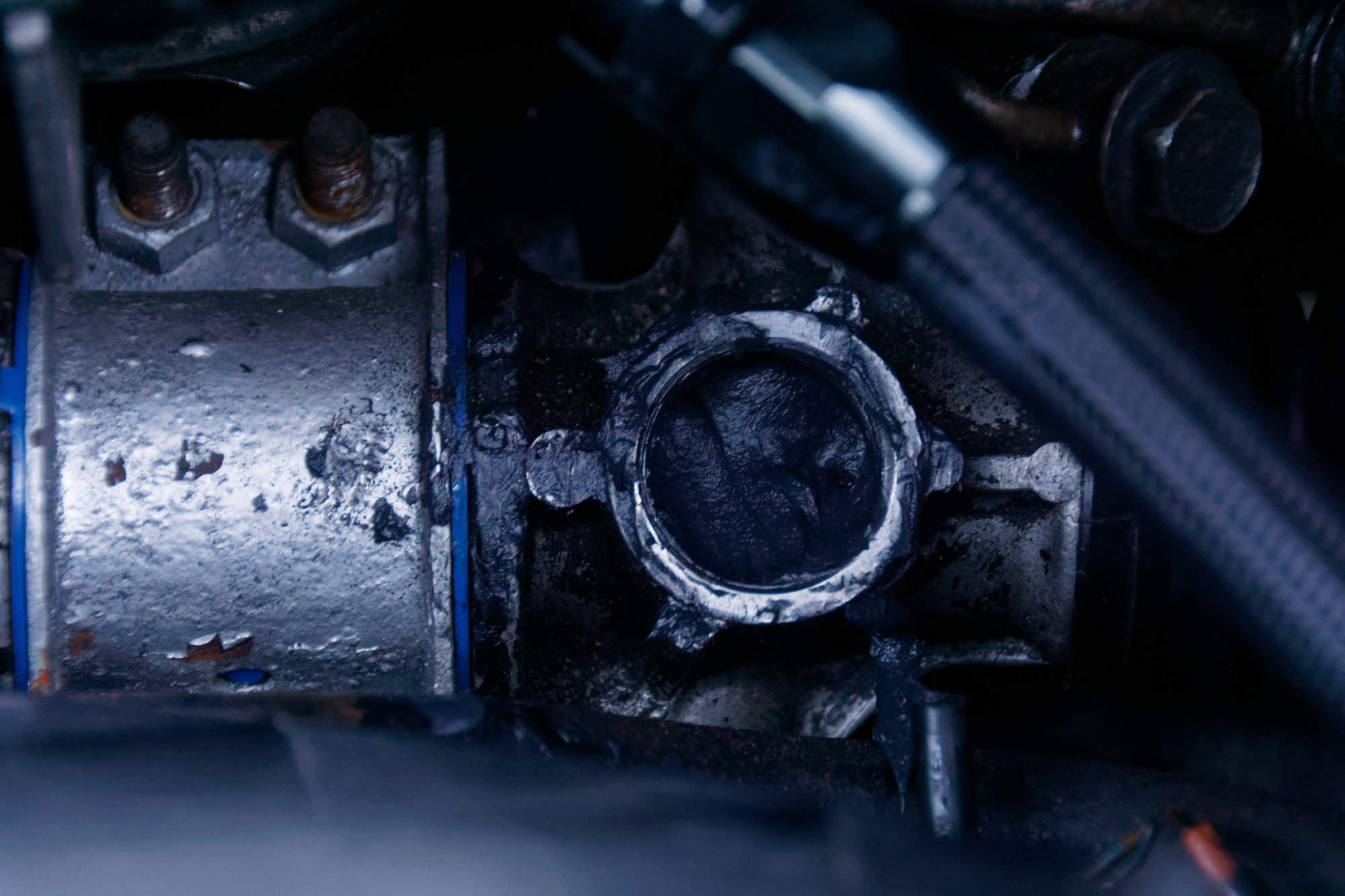
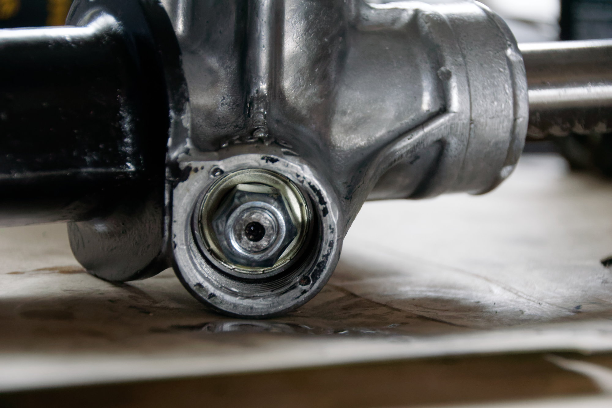
The seal kit arrived while I was at work today and I found some time after for the tear-down and cleaning. First comes the removal of the yoke support and the bottom pinion bearing cover (I made up the name, I don't know what the real term is). If you've been reading the past few posts you're more than familiar with the yoke support, but the bottom pinion bearing cover is a 24mm nut on the bottom of the rack. Look under it and you find:


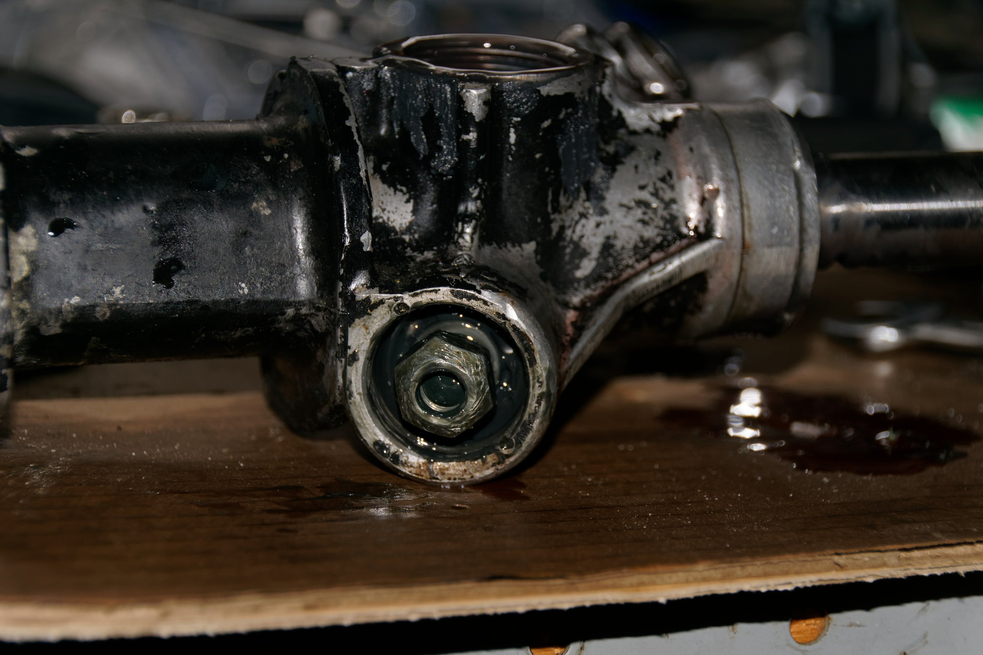
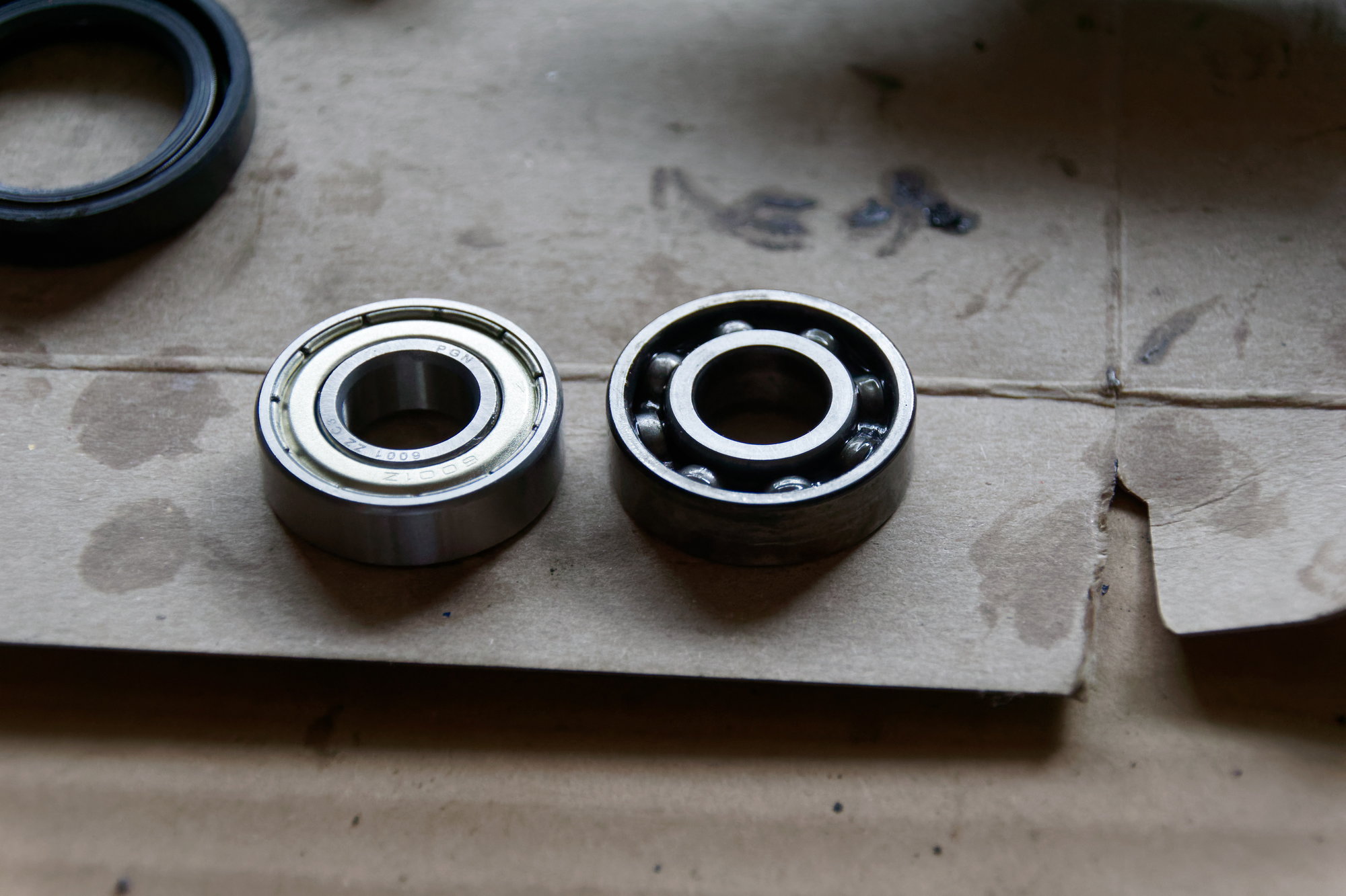
The bottom pinion bearing; what else? Also though, you do find a 17mm nut that you definitely tightened before assembly but is now floating around loose on the threads. I distinctly recall torquing this to spec and now it's completely loose, so maybe some blue loctite is in order this time. Although it may be the fault of the bearing somehow, since this one is toast. Spinning it around has that distinct "crunchy" feelings that bearings get when it's time for them to go to the big toolbox in the sky.

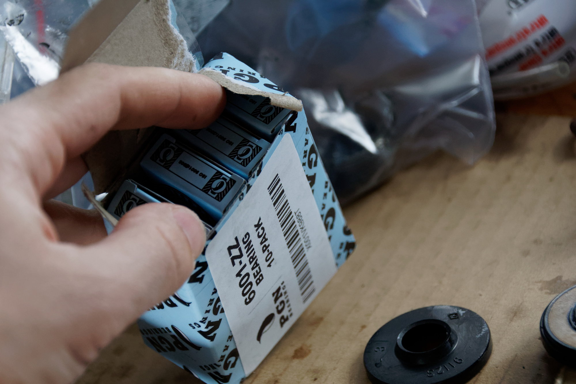
The part number is Koyo 6001. I found a compatible part on Amazon with next-day delivery, 10 pack for $15. Generally I just prefer to buy Koyo / Timken the first time, but at that price I decided to just roll the dice. So much like those ball-bearings for the yoke support, if anyone needs a bottom pinion bearing, just let me know.

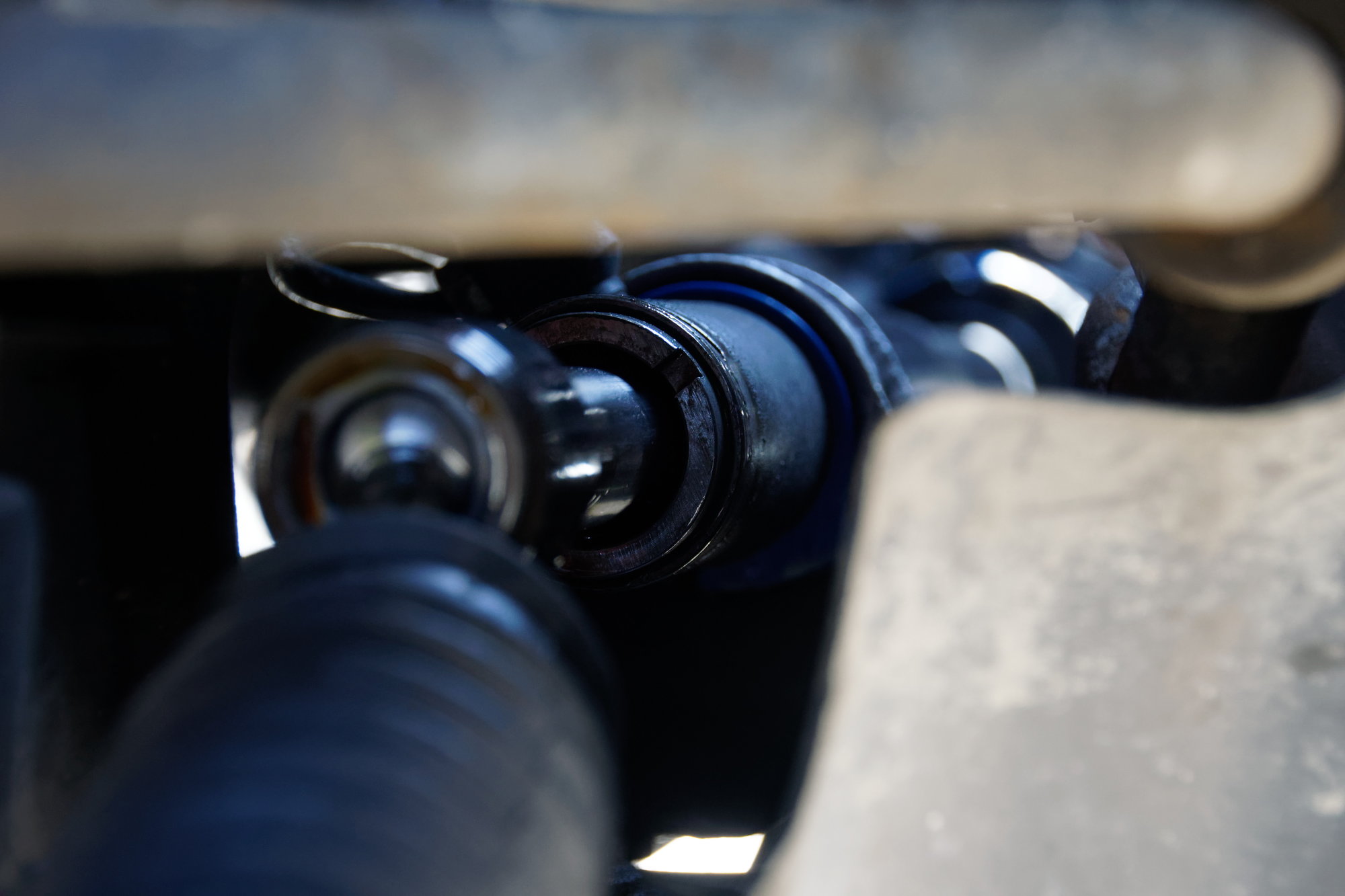
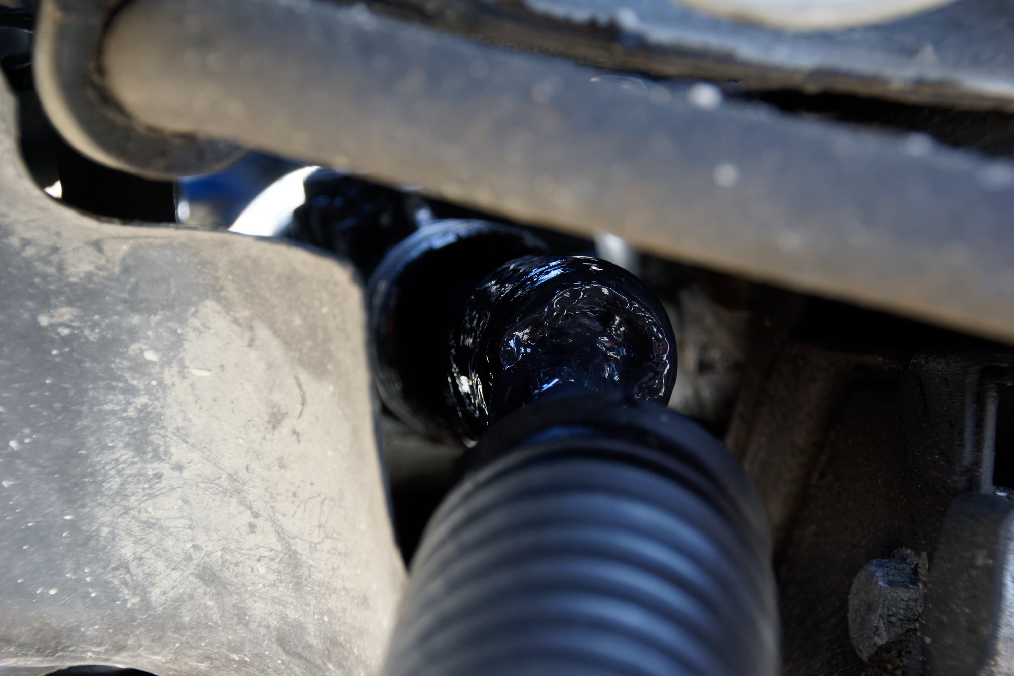
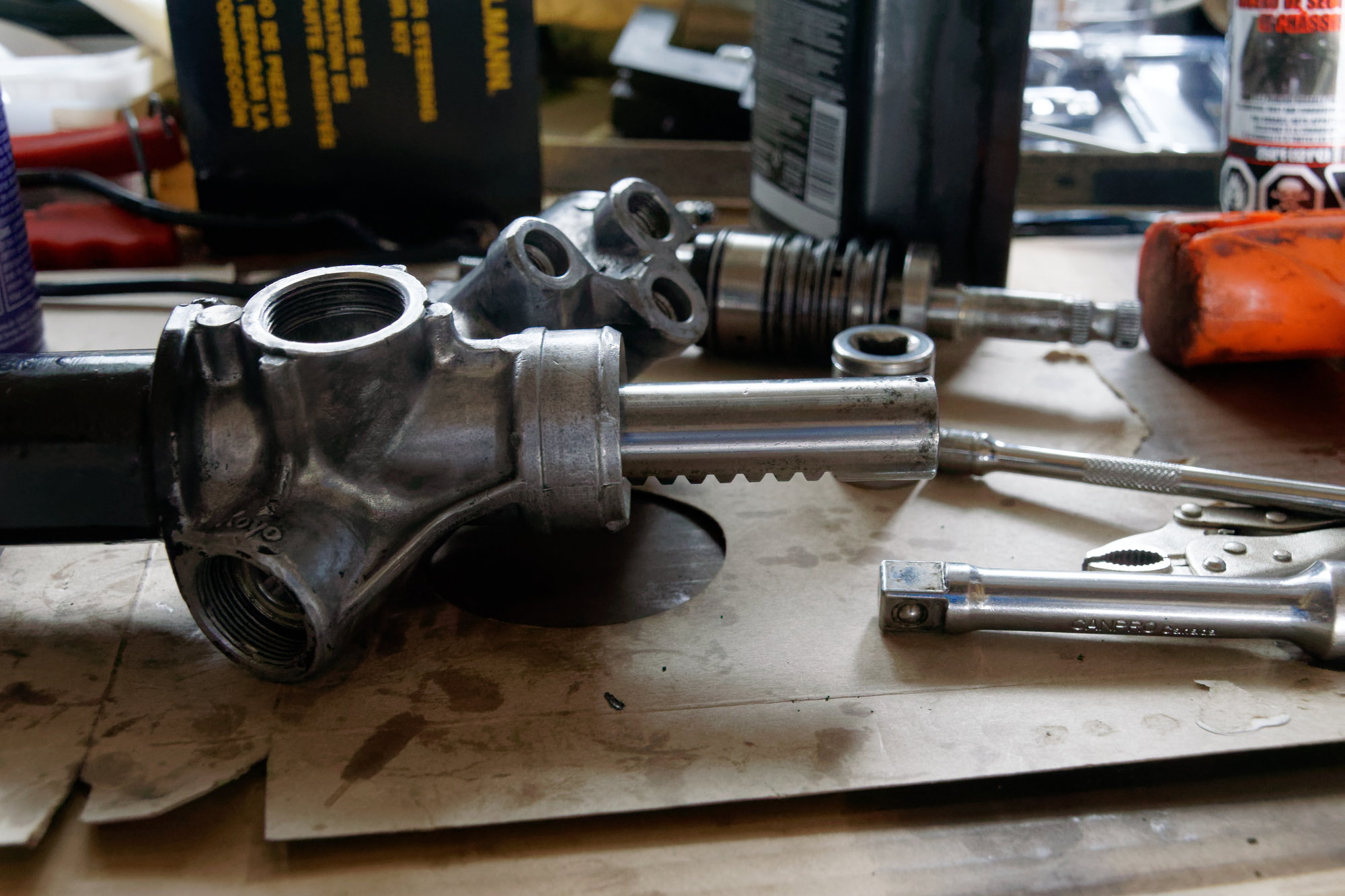
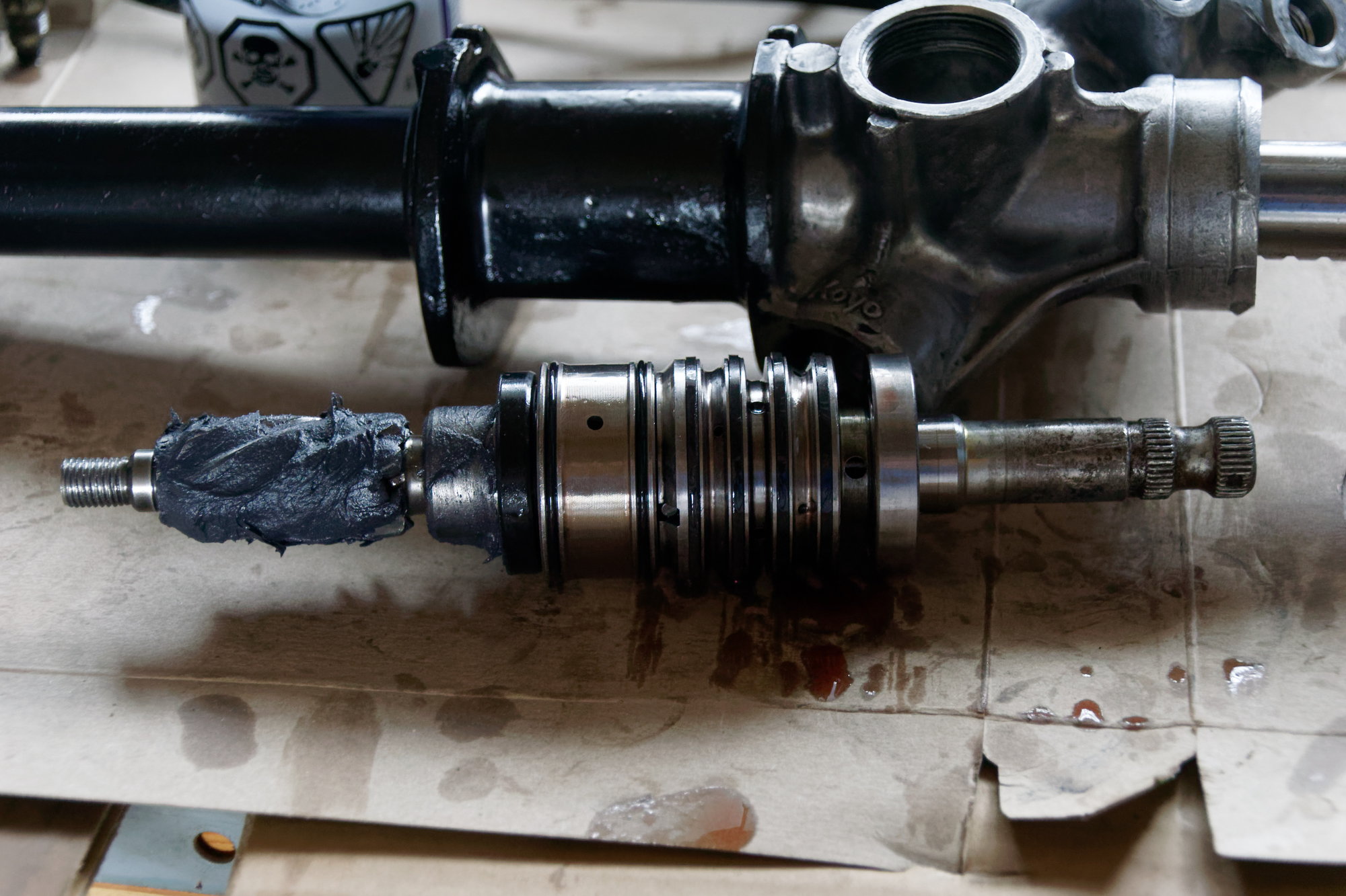
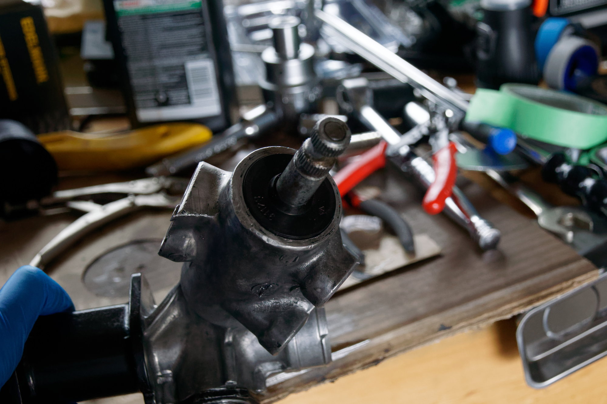
Next I took off a dust cover and snap-ring on top of the pinion. Then you can take the pinion assembly out by gently tapping on that bottom nut until it's loose in the housing, and removing the nut before pulling it all the way out:


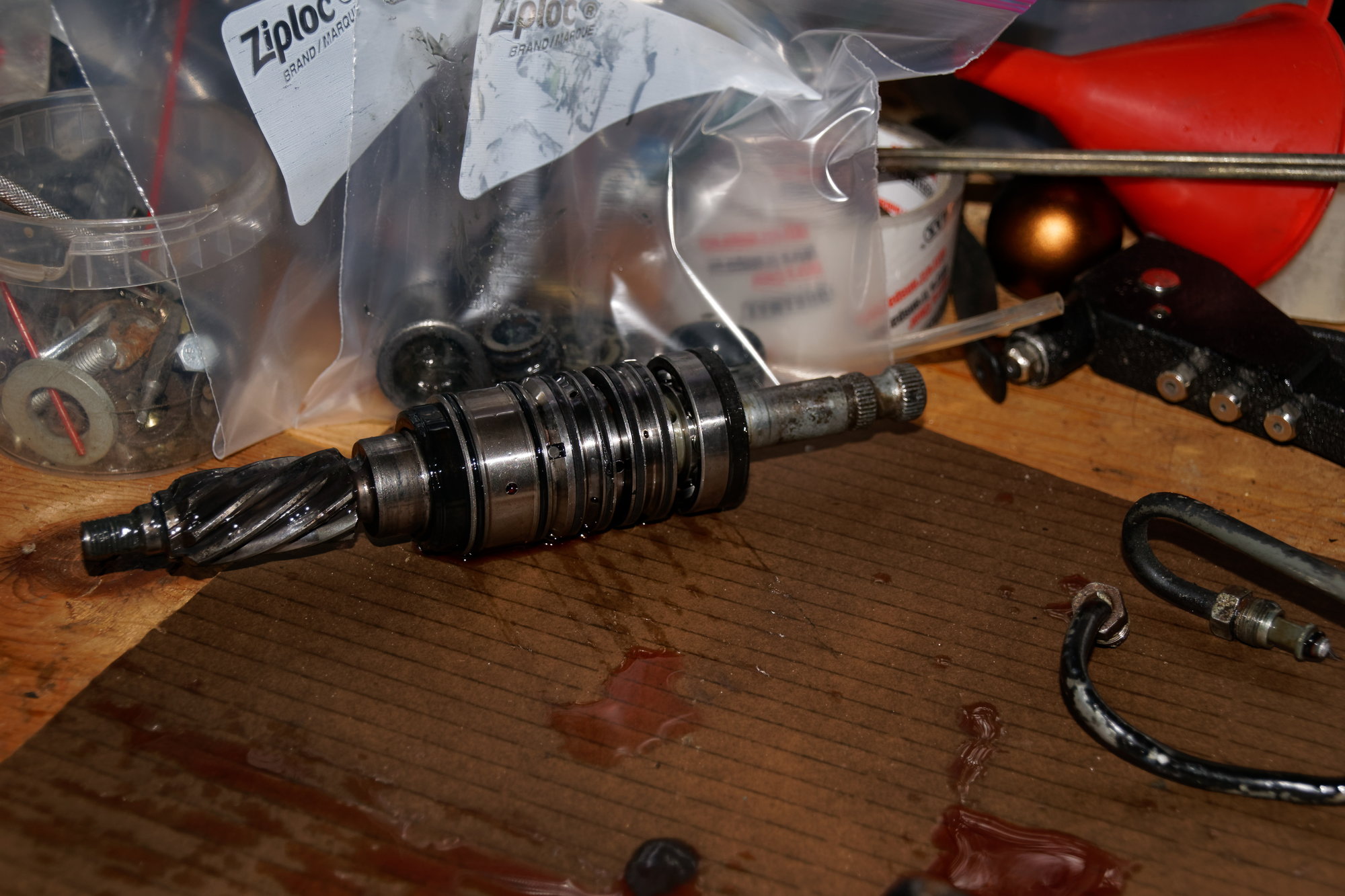
The top bearing and bottom oil seal came out with it, which is normal. This part does the "magic" in a power steering rack. When you are turning left it pressurizes the one side of the piston and pushes the rack left, while allowing fluid out from the other side of the piston (through those hardlines). When turning right, it pressurizes and de-pressurizes the opposite sides and turns right. This way the pressurized ATF does the work for you, which is pretty nifty. Now that's my layman's understanding, and there are also some wacky things going on with the third line for the "reaction force" tube that I don't entirely understand. Basically it seems like that line senses how much pressure is opposing the turning motion of the tires (basically whether there is significant resistance like hot asphalt, or little resistance like snow) and does something with the valve in the pump to better react to road conditions. Again, layman's understanding.

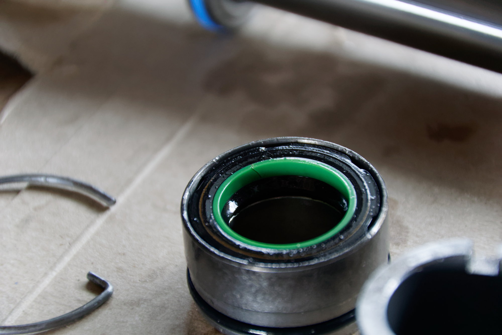
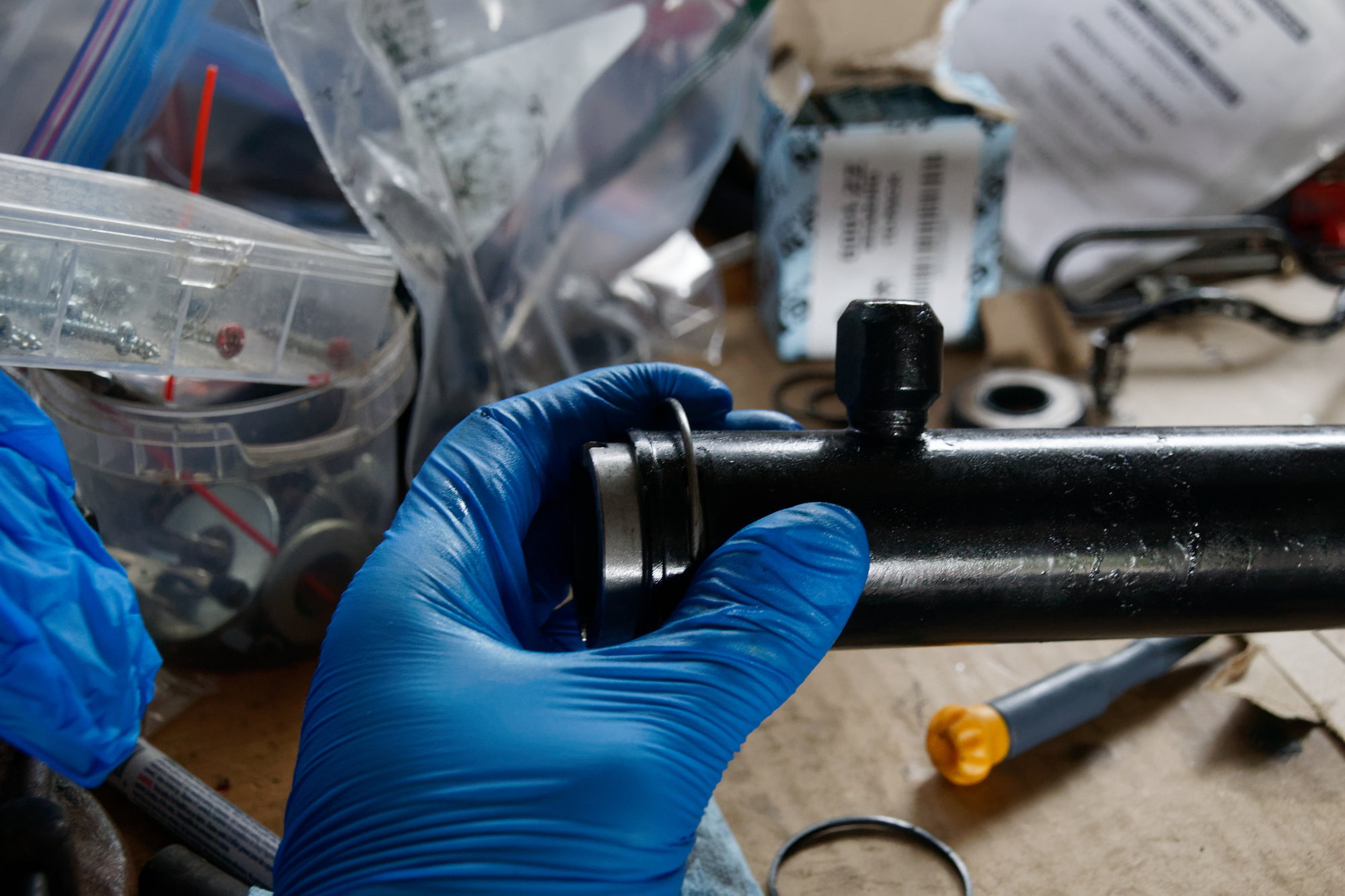
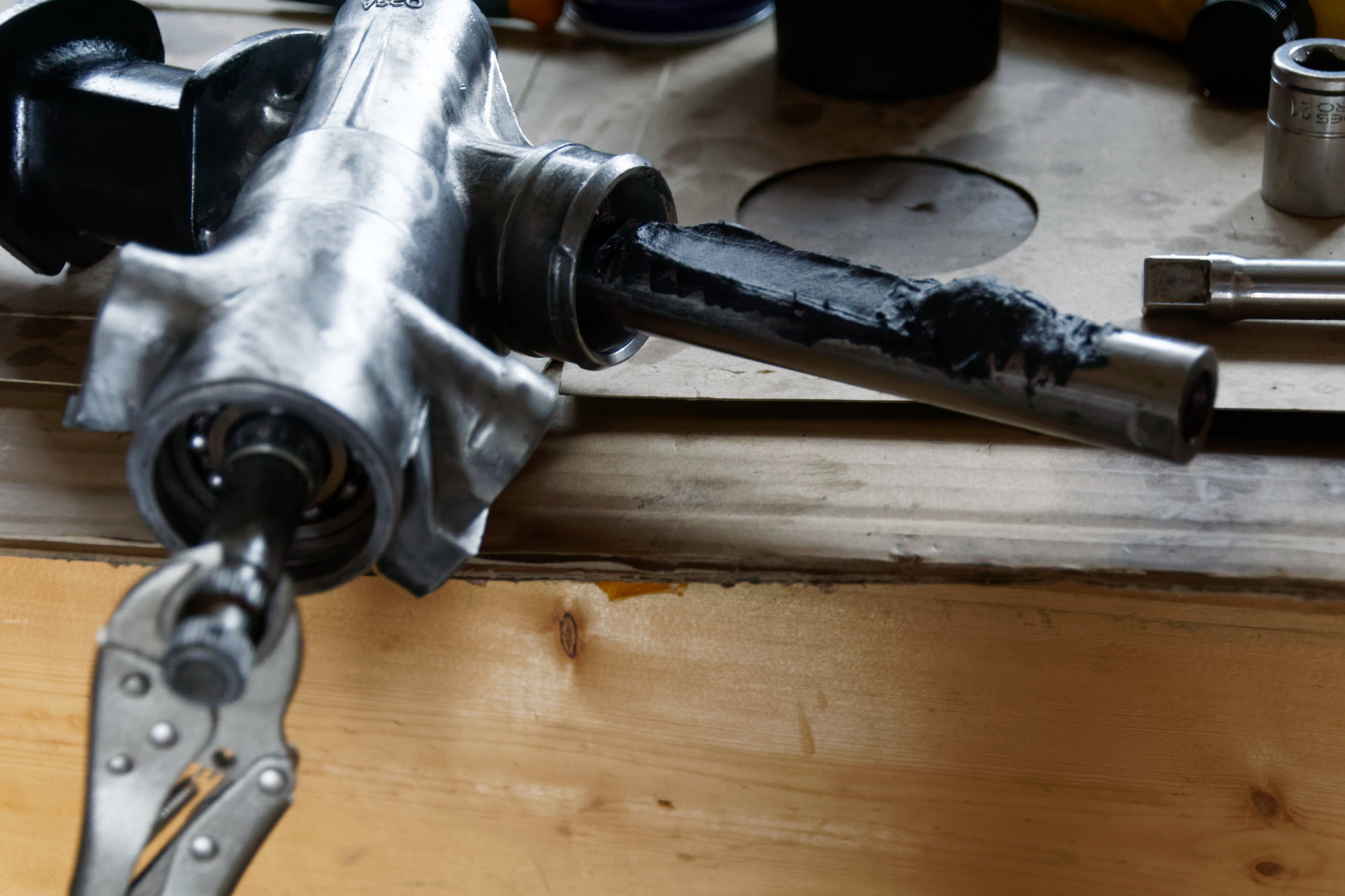
Then I removed the hardlines from the back of the rack. They run from the pinion housing to the ATF side of the rack, and are what carries the actual pressurized fluid to press on the piston and move the rack. Next you need to remove the rack stopper:


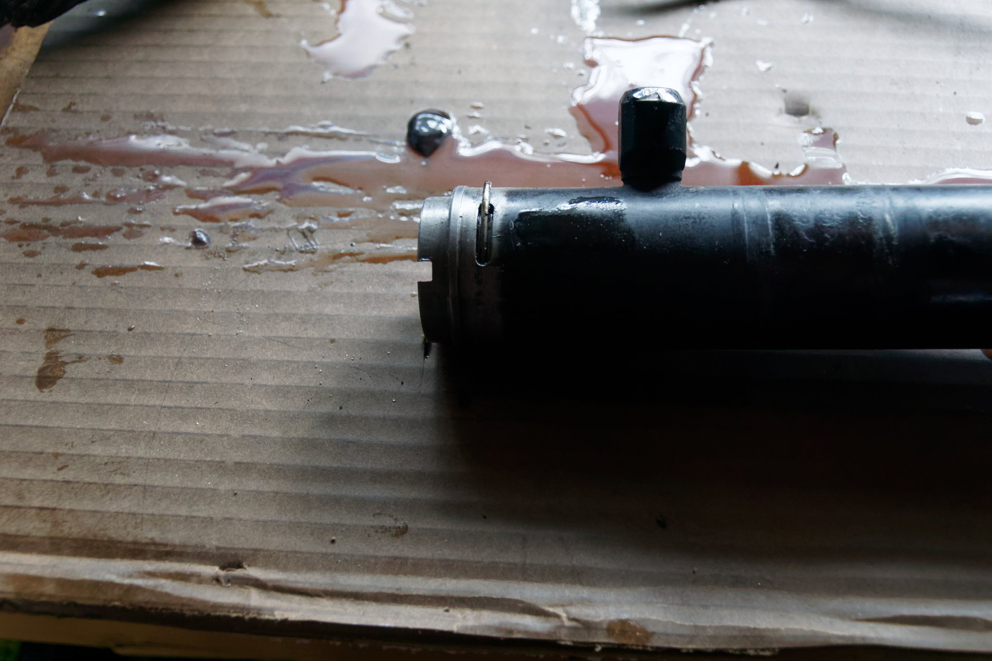
A screwdriver fits through those notches, then you rotate the little steel wire out of it's groove. Then the stopper pops out. After the stopper is removed, there is a fluid seal that sits inside a steel bushing, with an o-ring on the outside to seal against the tube. This is removed by gently tapping on the gear side of the rack with a dead-blow hammer and extension, basically using that piston on the rack itself to gently push the bushing and seals out. Then the rack is free:


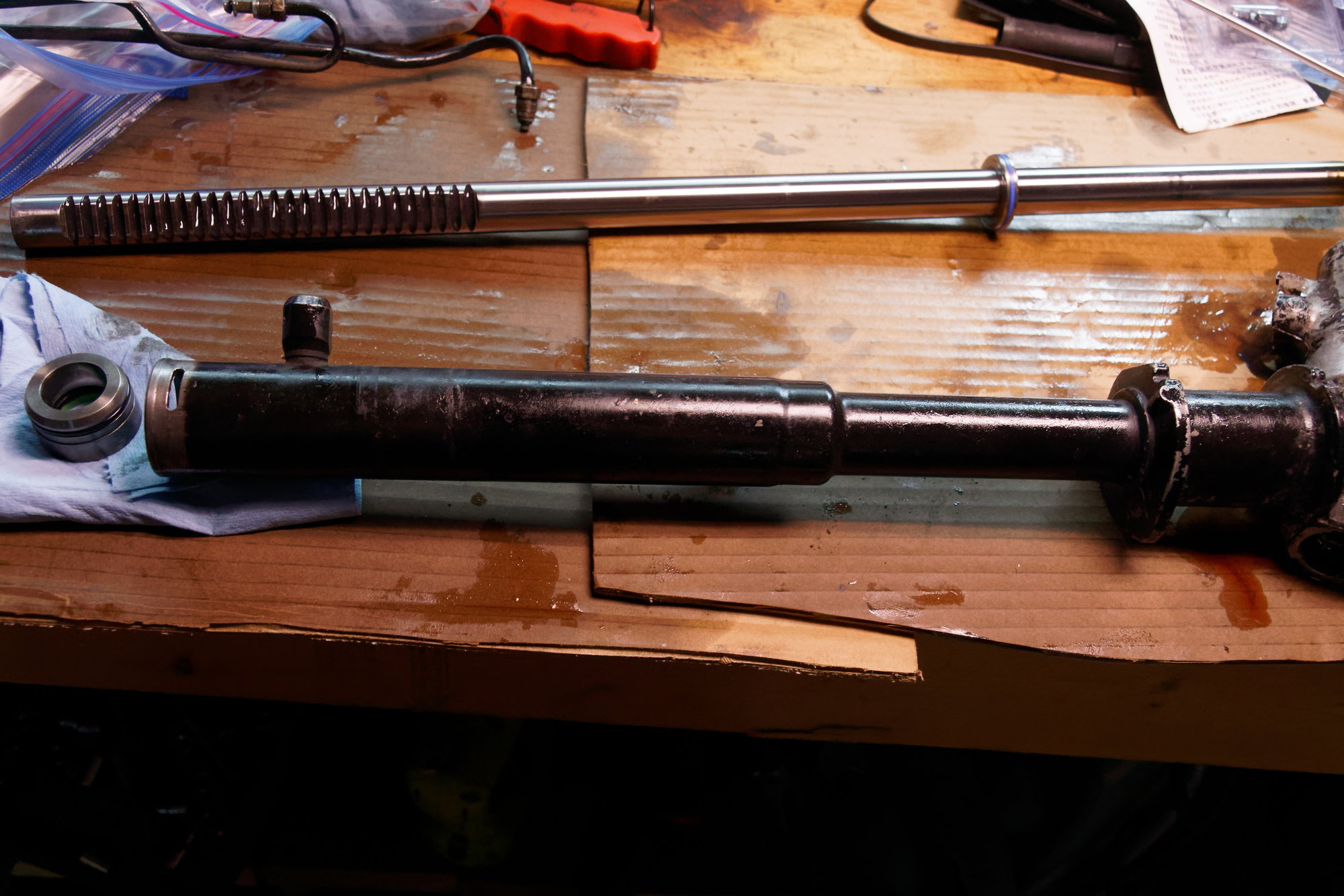
Then I used a 19mm socket and multiple extensions as a dead-blow hammer to remove the inner ATF seal and it's support piece:


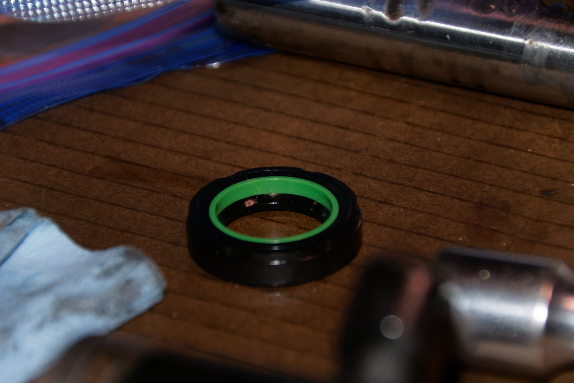
This is the seal I mentioned before that is tough to install. It needs to slide over the toothed side of the rack, so it's easy to snag it and crack the plastic insert. I was 100% sure I got this right last time (practiced with the old seals a few times too), but it's clearly cracked. At least I have a likely culprit for the failure.

The last step is to remove the bottom pinion bearing. A socket and hammer (noticing a theme here?) made quick work of it. Note that a puller (blind-hole puller?) is the correct tool, but I don't have one. There is also a Mazda SST for the inner seal and support I mentioned above, but I don't have that either and the bearing & extensions work just fine as long as you take care with it.

After that it's time to clean everything very, very thoroughly and inspect for damage. The rack was exactly like I remember it last time; there is only one place with any visible wear:


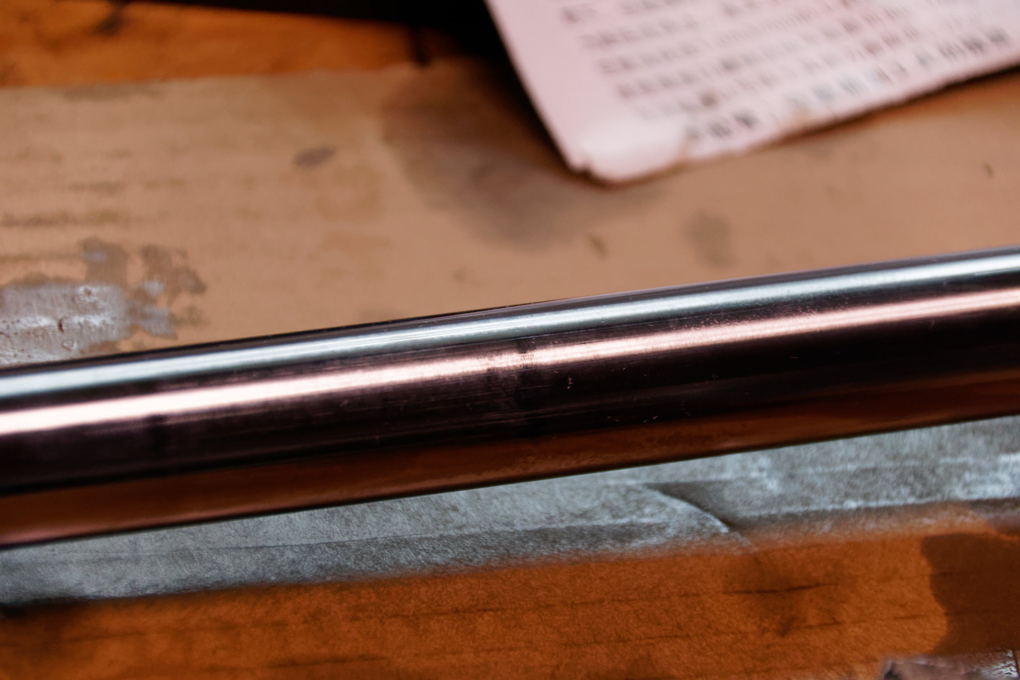
The flash makes them look worse than they are, but they're barely visible to the eye. I'm wondering if the passenger's side tie-rod boot was compromised before I bought the car. There are no tears in it now, but it may have been replaced before.

I tried and couldn't feel anything that I could catch a nail on. With little else to go on (there is no procedure in the Factory Service Manual on what the acceptable wear is or how to measure), I'm using that as my barometer and calling it fine. Anything I do to try and improve it is liable to make it worse, so it's staying as it is.

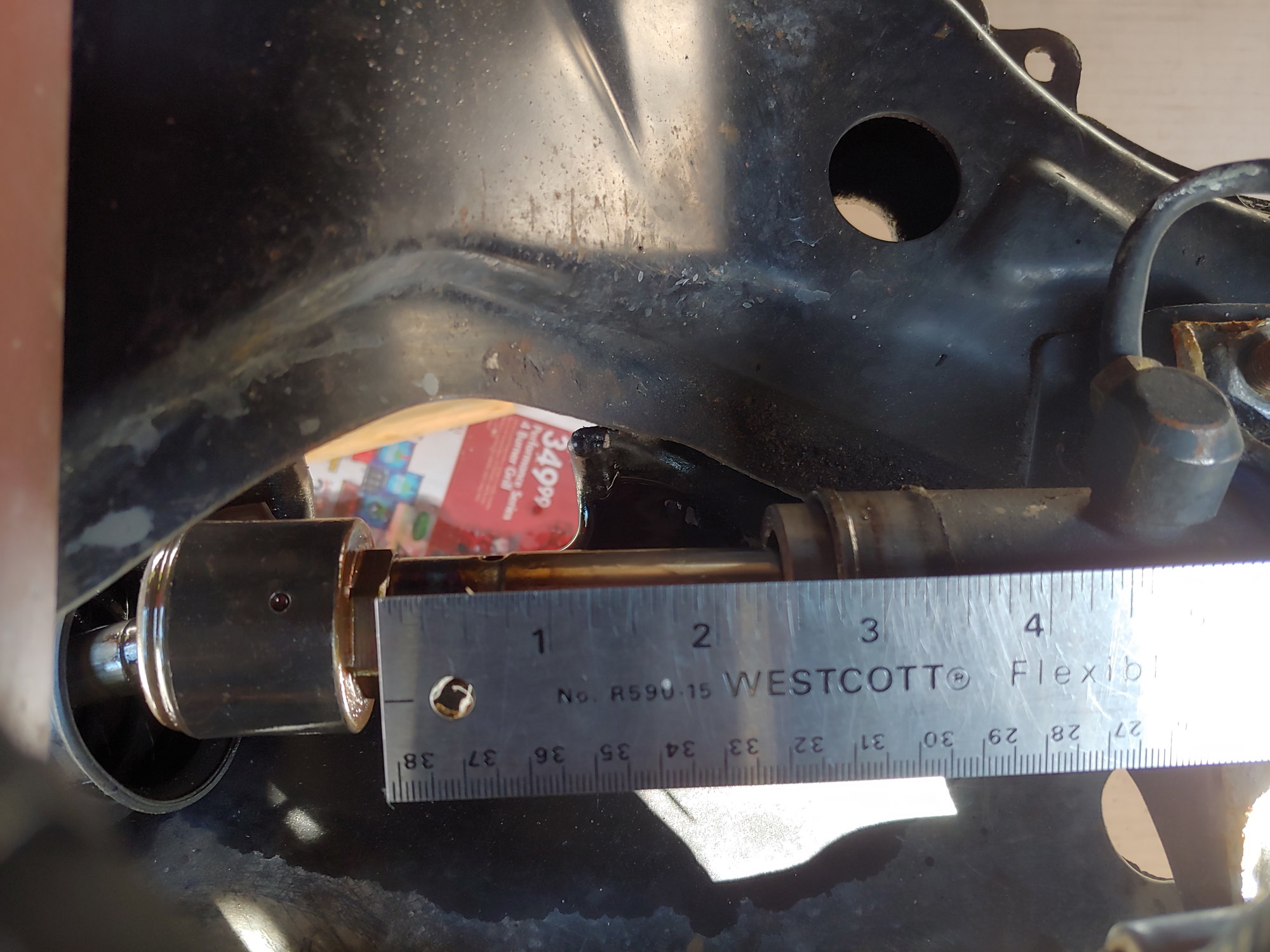
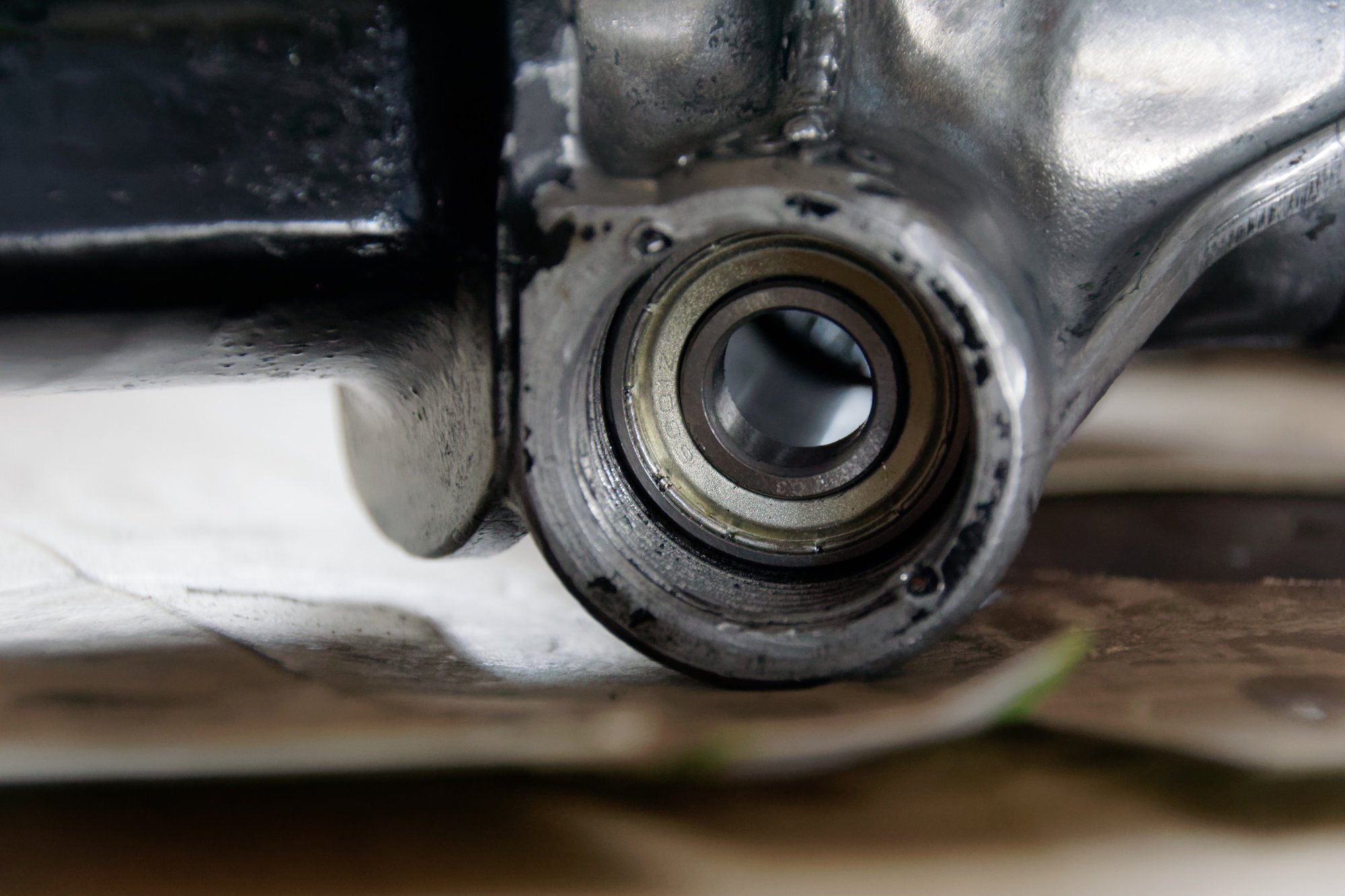
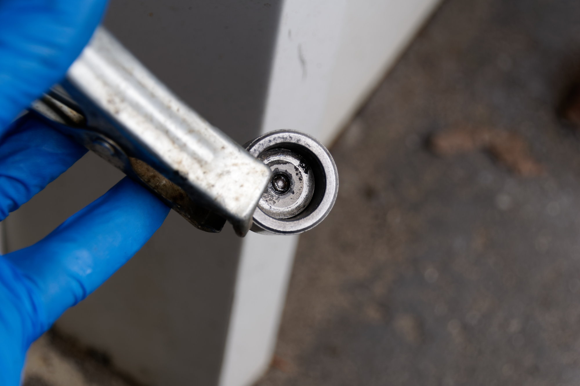
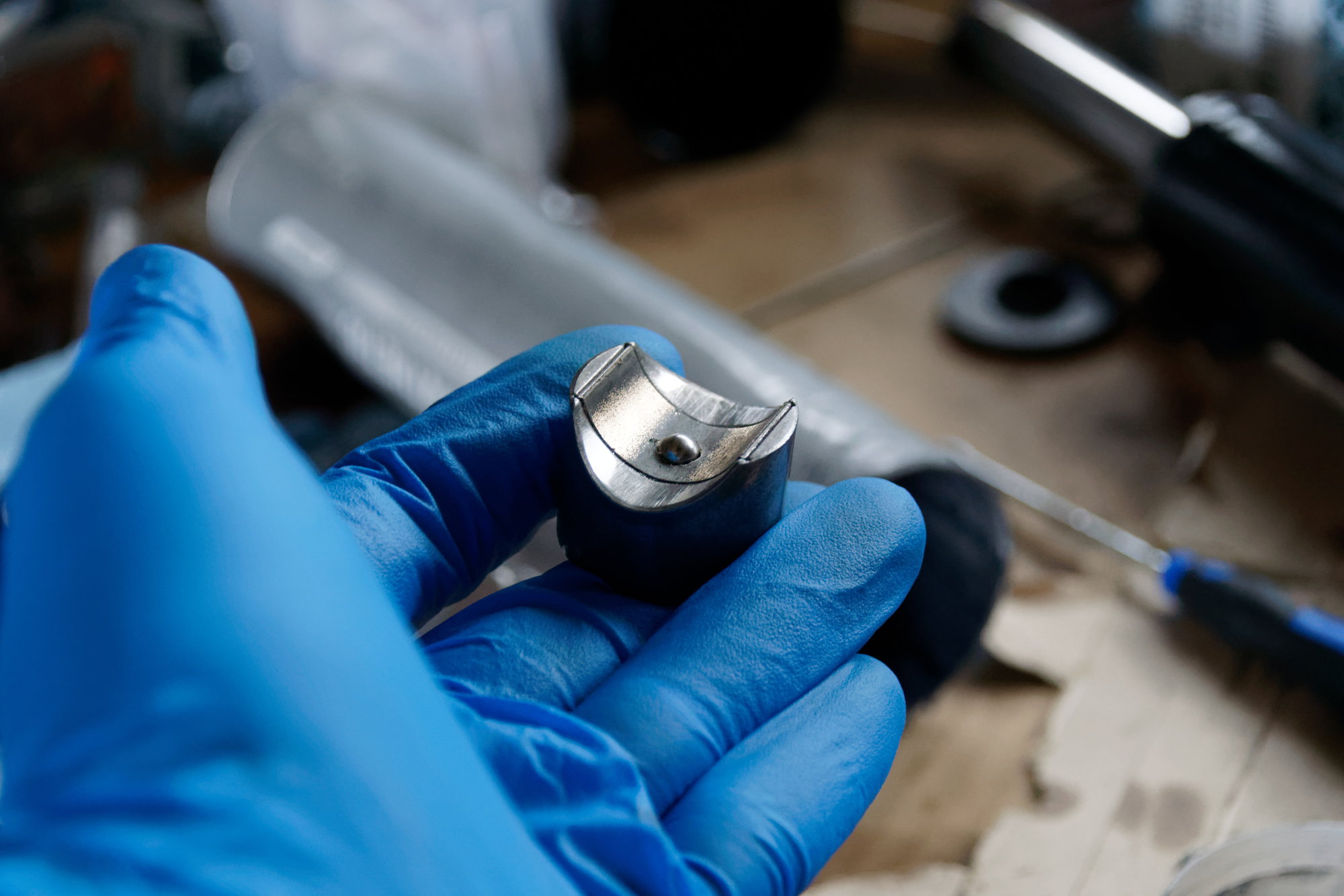
This is the best picture I could get, but there is one more bearing we need to concern ourselves with:


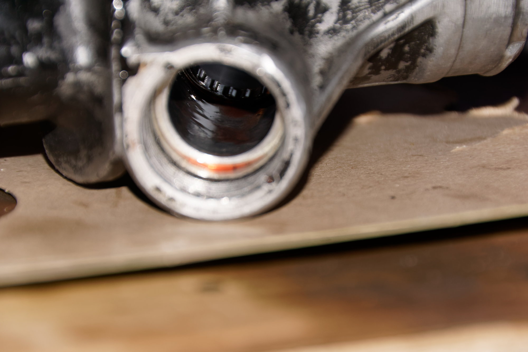
Don't damage that needle bearing! Apparently Mazda doesn't acknowledge the part at all, it has no part number in the microfiche, and it's a non-standard side making it difficult to find a replacement. Let alone actually getting the old one out and the new one in. Thankfully mine is nice and smooth, so I don't have to worry about it.

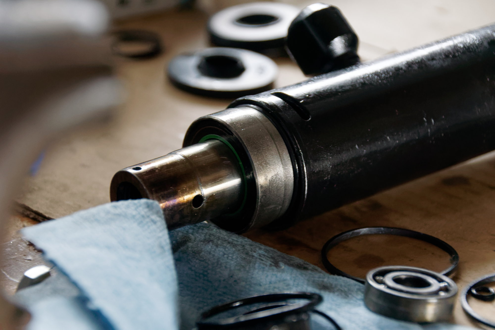
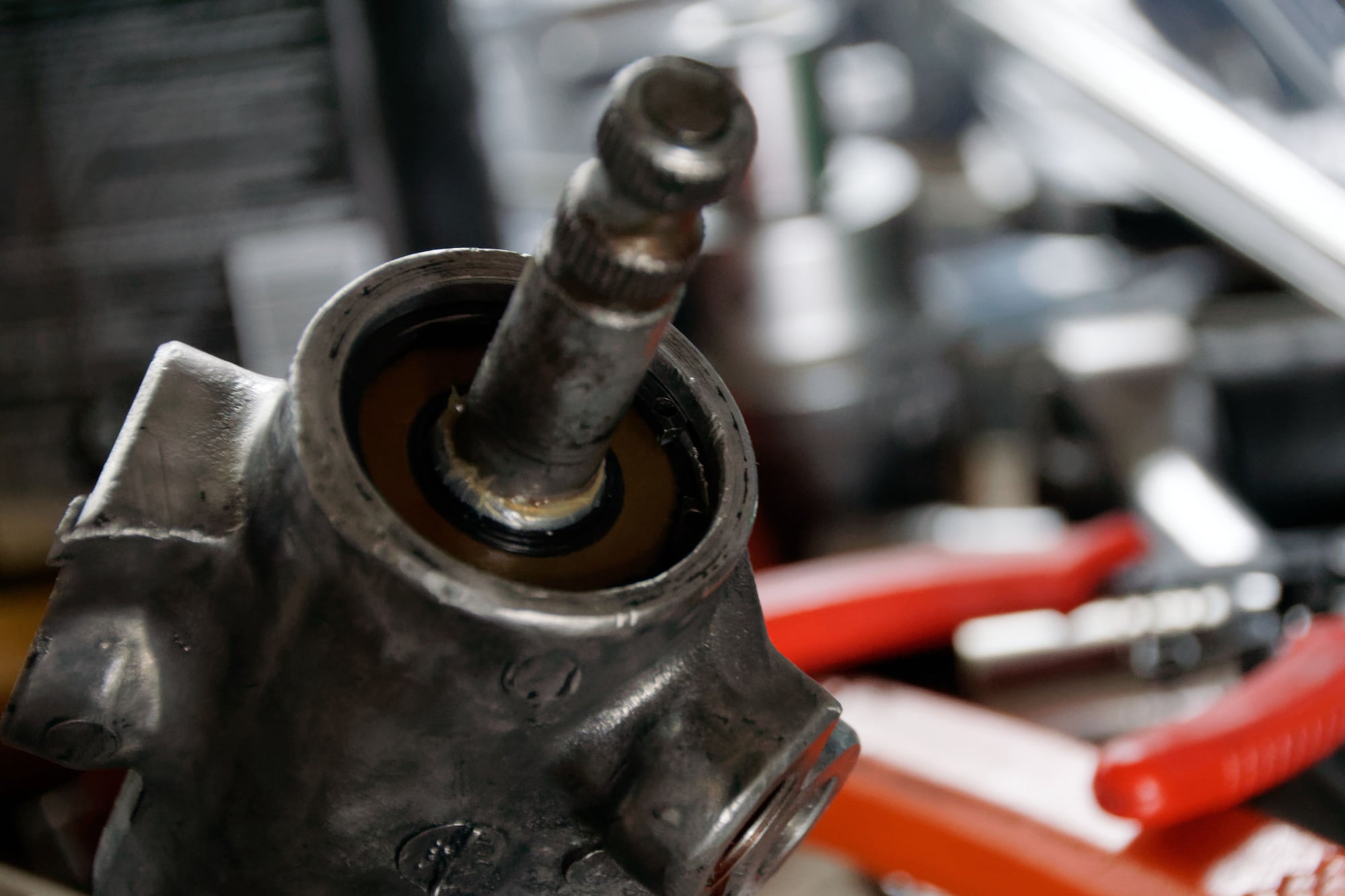
Next I got the inside of the rack squeaky clean. Photographing this is a challenge, so this is the best I've got for you:


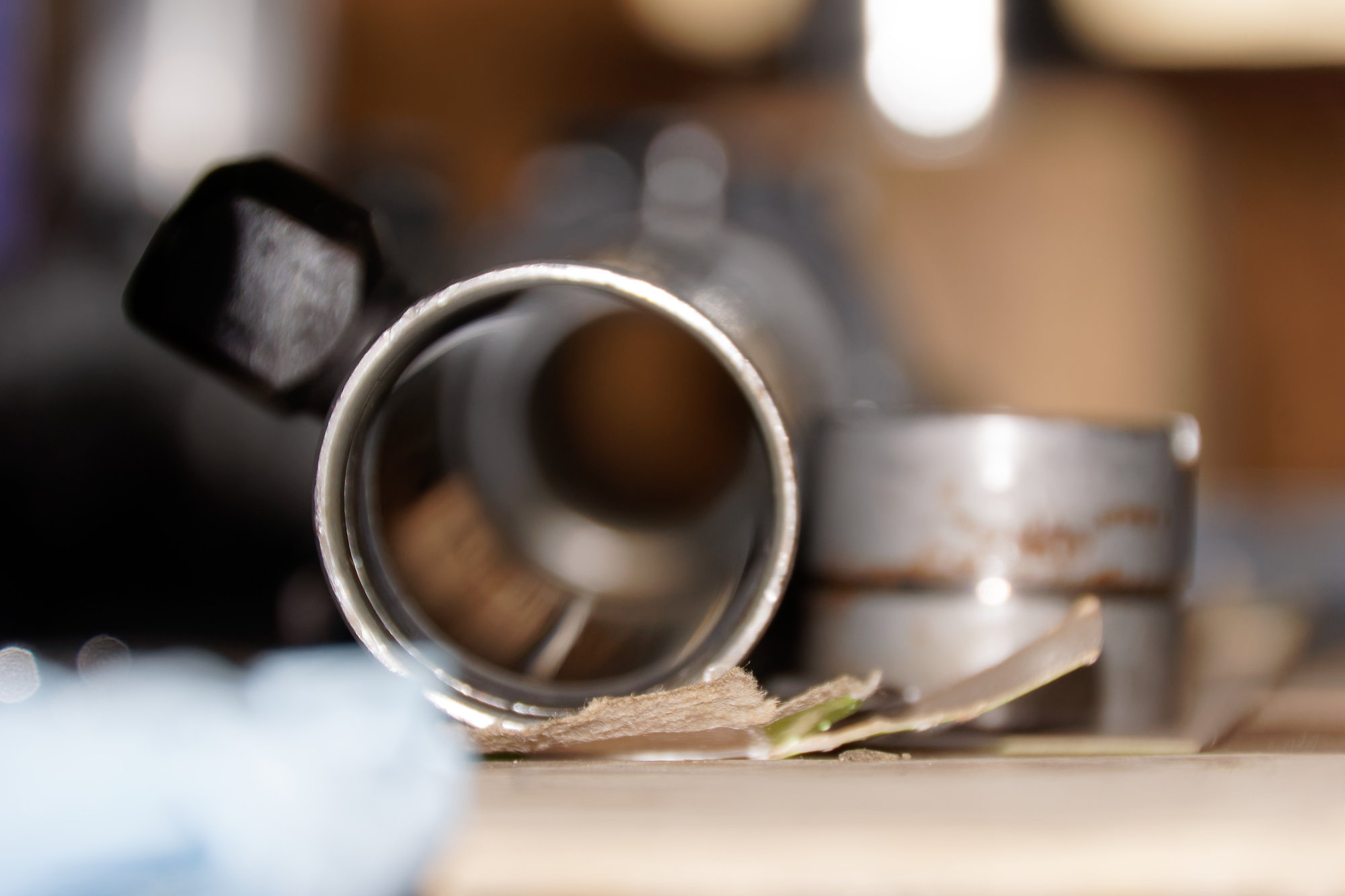
It's super smooth, so it looks like it's in good shape for the rebuild. Copious amounts of brake cleaner and a blue shop rag on a stick took care of the cleaning.


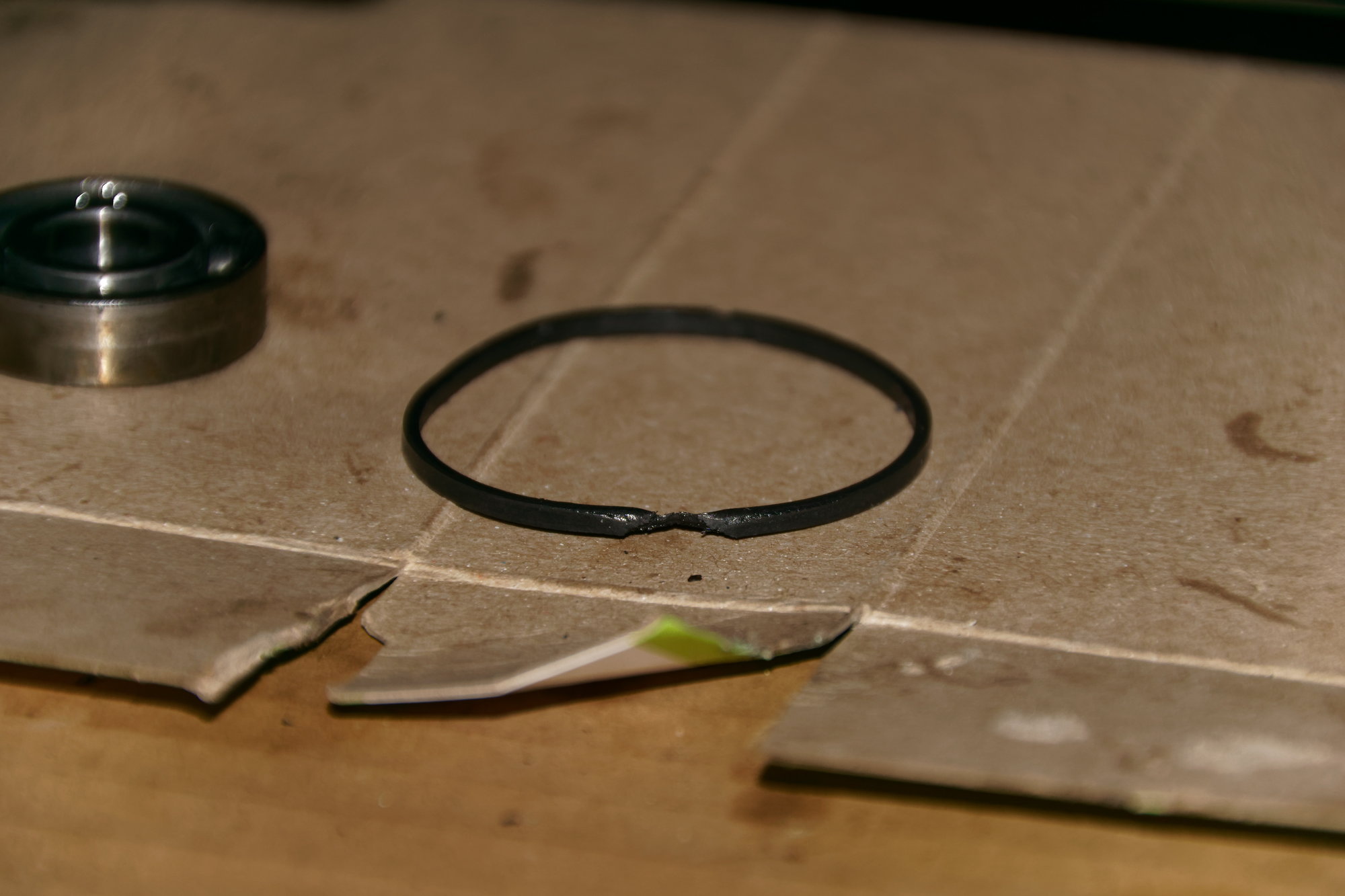
And the last part of note; one of the old seals on the pinion. There are four of these, and they are the least flexible seals I've ever seen. Take care not to break them when installing. This is one of the old ones I pulled out, and that is NOT the side I used the pick on to remove it. That was already there. And I definitely didn't assemble the rack with it damaged. I can only assume that either I snagged it on the install, or it was otherwise compromised and then the loose nut on the bottom of the pinion allowed it to wobble and wear down. The pinion, however, shows no signs of unusual wear or contact with the housing. To sum up: It's almost certainly something I did wrong, I just don't know exactly what.

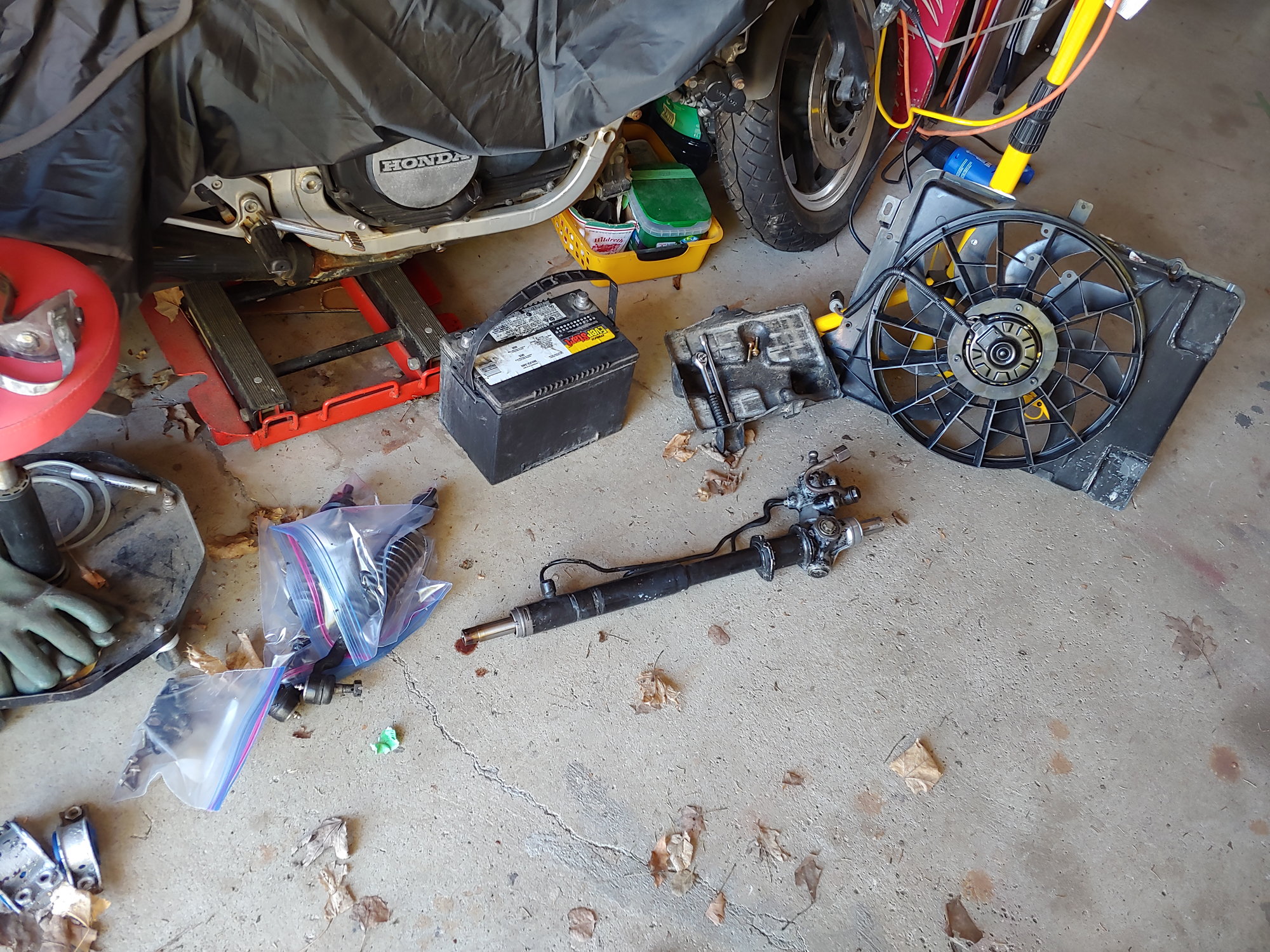
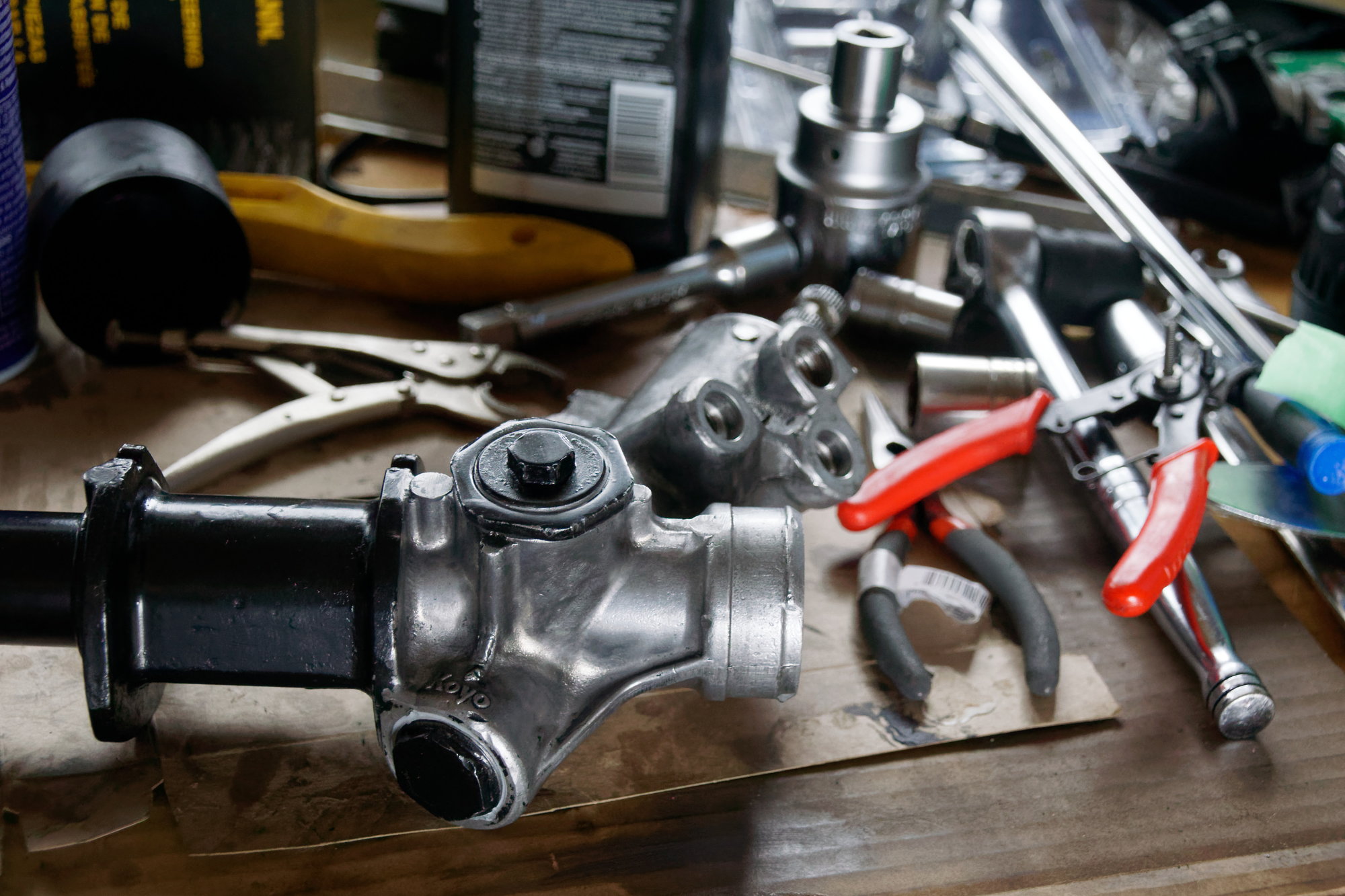
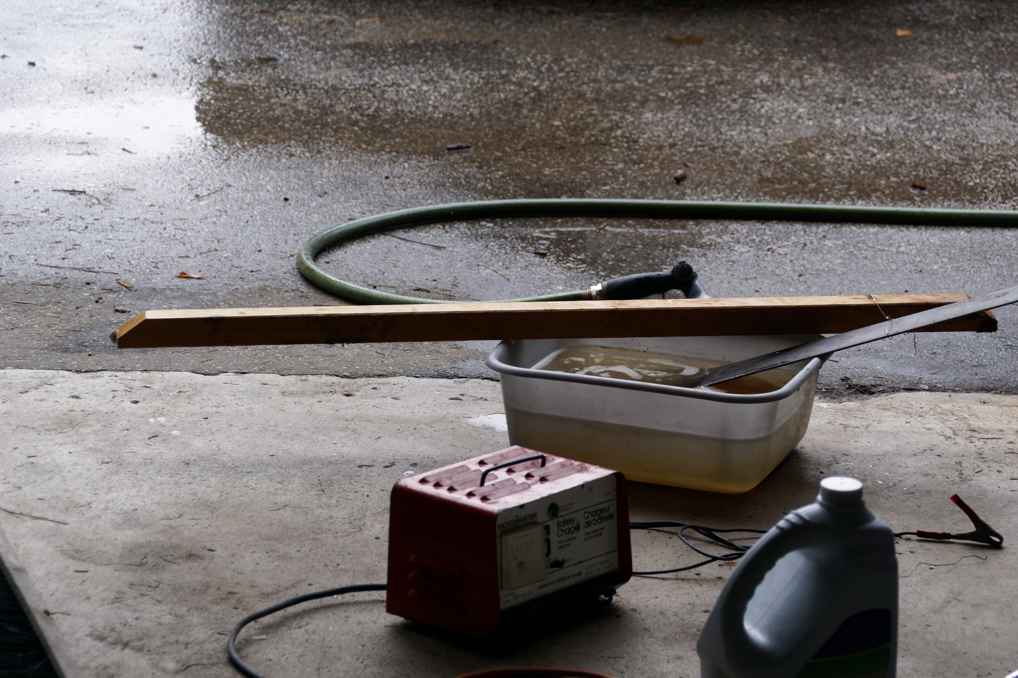
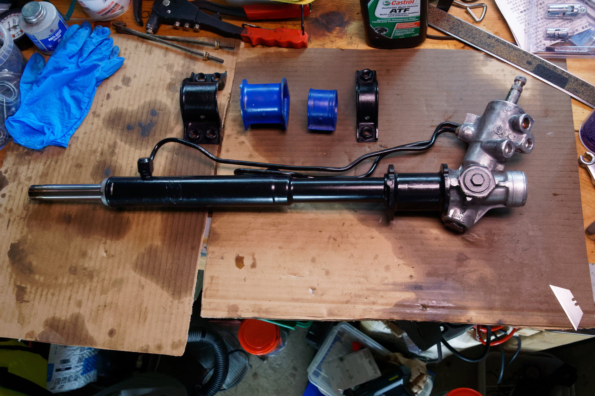
Lastly, here's a photo of all the cleaned pieces. It took an hour at least, but they are all clean of grease now:


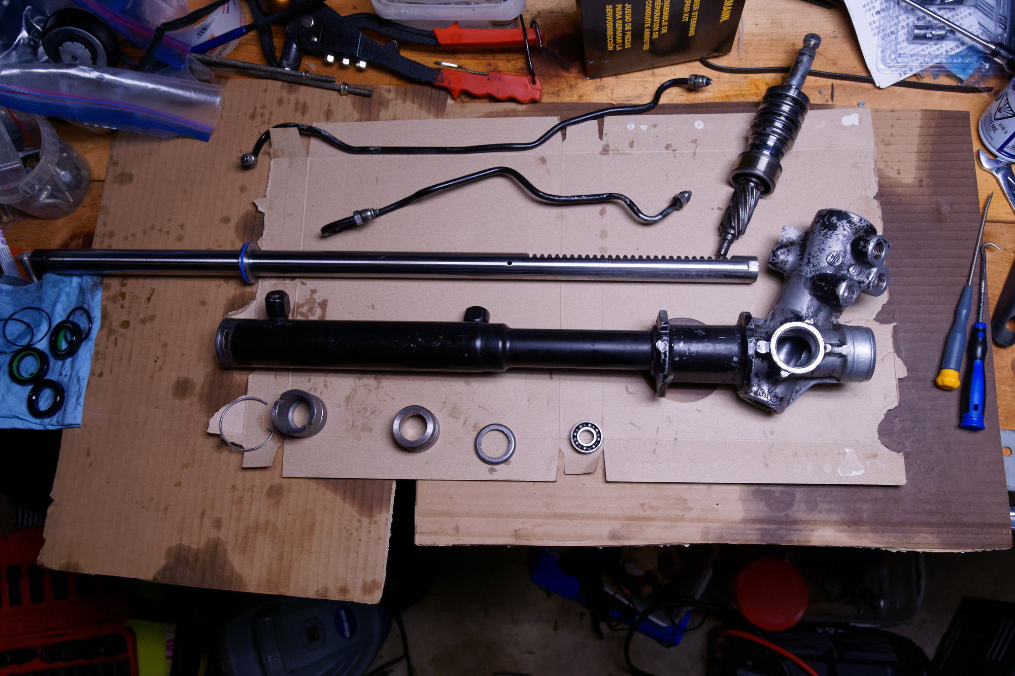
Please ignore my very messy workbench and the surrounding detritus. You can also see some marks on the back of the toothed portion of the rack. These are from driving around without that ball-bearing for awhile, but are just some light marks and won't affect operation of the rack and pinion. That part of the rack doesn't see ATF, only grease, and is only sealed by the dust-boot. After all that work cleaning, I immediately undid it by covering everything with a light coating of ATF. Rust never sleeps.

The bearing should arrive tomorrow, and I'm going to pick up some paint to make this look a lot nicer. I'm thinking I'll remove all the paint from the aluminum pinion housing and leave it bare, then get some satin black for the ATF side of the rack since it's steel. If all goes well the update should be soon and hopefully the rack is back in by Wednesday.

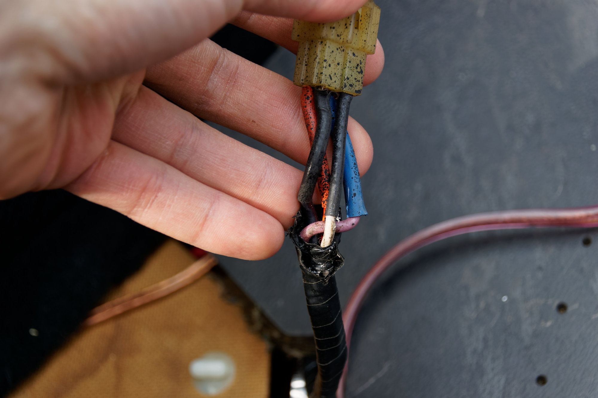
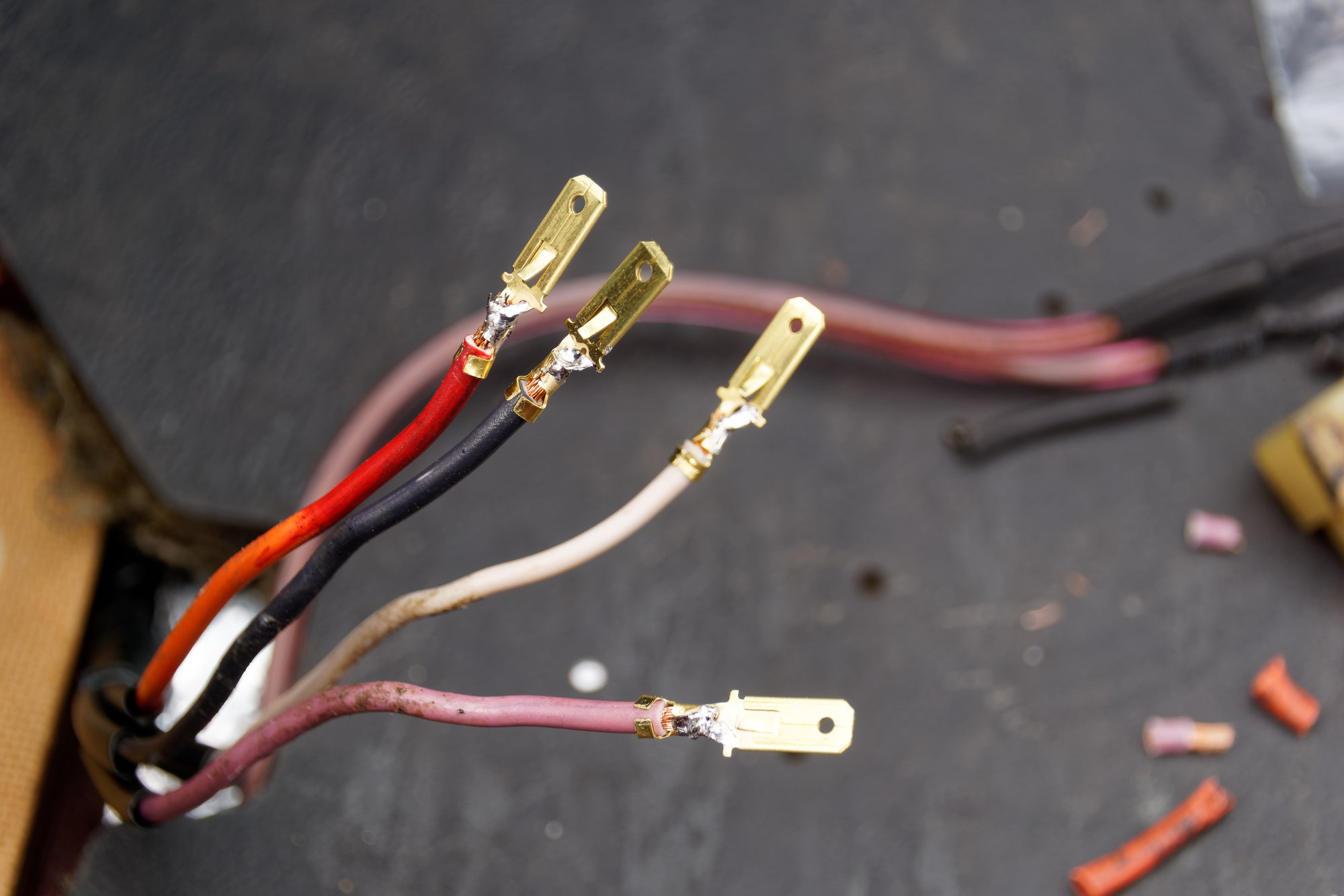
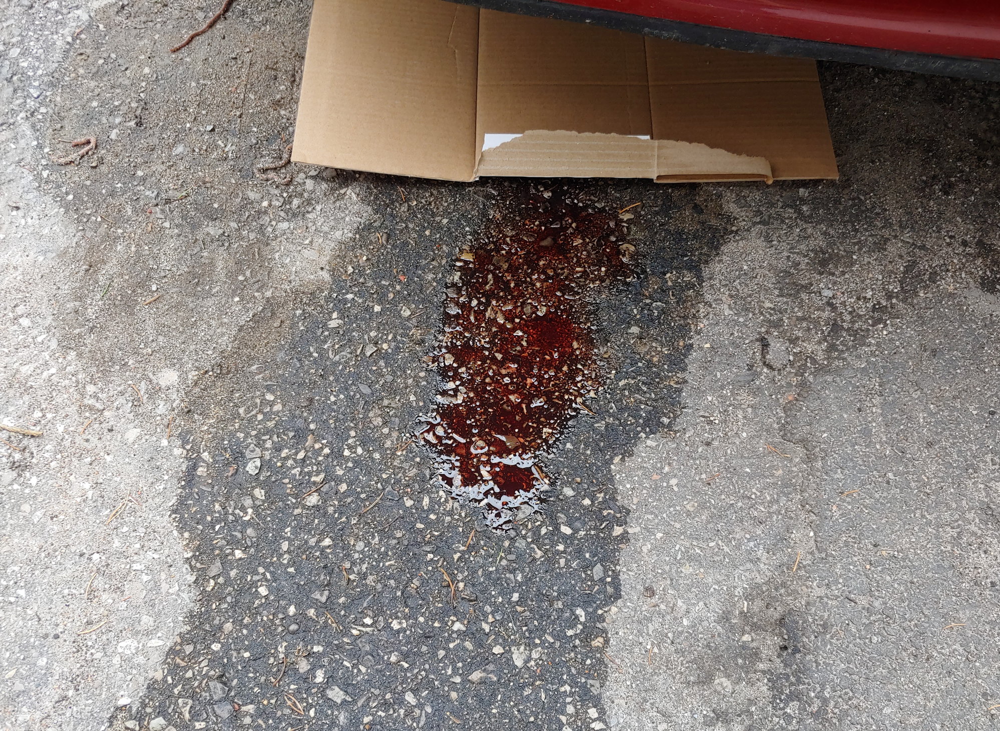
In other news, I was working on the brake lines near the master cylinder and when bleeding the brakes afterwards the rear left soft-line started to leak from the fitting. Not the fitting where it meets the hard-line, the actual crimped connection. Yikes. I've put in an order through Mazdatrix, and though my wallet hurts ($90 USD for the lines, $45 USD flat rate shipping to Canada, then exchange, and customs is inevitably going to rub salt in the wound), I know these lines are DOT approved and should last a long time. I don't remember where exactly I got the old braided stainless lines, but they clearly weren't good enough and I'm glad it failed in the driveway instead of on the road.

Until next time :)

WondrousBread
WondrousBread New Reader
5/3/22 5:13 p.m.

The bearings came in from Amazon as expected, so having everything I needed I rebuilt the rack today. Reassembly is more or less the reverse of disassembly. In fact, the job really only takes about an hour, but this turned into about 6 hours because I decided to worry about the cosmetics. I ended up using a wire-wheel on an air die-grinder to remove all the paint from the pinion housing, to the right of the mount. Then I cleaned and scuffed the rest of the rack before painting with VHT satin black chassis/roll bar paint. I've used the gloss version before and it's super tough stuff, so hopefully the satin is tough as well. The hardlines and mounts got the same paint. Photos of that to come, but first the mechanical bits.

The inner seal goes on over the teeth as I mentioned, which is the seal you need to be super careful not to damage. Then the little steel collar goes on with it, and the blue o-ring goes on the piston:


I noticed something interesting about the green seal though. Notice the following, and keep in mind this is the NEW seal:


Yup, they all have that notch. I checked both old ones and both new ones, they're identical. This means I didn't screw it up last time. Maybe the o-ring on the control valve was the culprit all along, and the shaft seals started leaking from over-pressure or something.

Anyways, the next step is to put in the rack, then use the geared end to bang the inner seal and metal collar into place. That Mazda SST is probably a more elegant solution, but this works:


Next I dealt with the bearing. The ones from Amazon have identical dimensions:


It's a sealed design, but in this application I don't see that making any difference.


Like I said, if anyone needs a bearing just let me know. I have 9 spares...

To install it, I just tapped it into place with a 21mm socket and the dead-blow hammer:


With that in place, I put the new rack seal and o-ring into the little carrier and installed it onto the passenger side of the rack:


Carefully popped that in. Then installed the rack stopper and made sure it seated completely, before winding in the wire retainer:


With that done, it was time to turn to the pinion and control valve. Not photographed, but I greased the needle bearing in the housing before installation. I put lots of grease on the pinion itself, and the control valve has new seals with lots of ATF. These are the least flexible o-rings I've ever encountered, so they need a lot of care to avoid damaging them:


Then after installing the pinion and making sure it was aligned, I installed the bottom lock-nut and torqued to the factory 22 ft-lbs:


To get the grease all the way into the rack, I slapped it onto the toothed section and then wound the rack back and forth a few times. This way I know it's all well lubricated:


To be continued.

WondrousBread
WondrousBread New Reader
5/3/22 5:14 p.m.

Continued:

I then had to improvise a solution for a slightly unusual problem. The ball-bearing I used in the support yoke cracked the hole in the yoke itself, and popped through to the other side. I've mentioned before that this part is NLA.


I first tried just putting a bead of weld on the back side, but that burned through immediately even on the lowest setting. So then I went to my second option, which was to drill out the hole very slightly and use the 5.5mm ball bearing I got on eBay with the others:


And well, it works fine. The ball-bearing spins easily in the cradle. Later when I installed the support I was able to torque it to spec, no issues. I did notice something interesting in the training manual though; It's only the manual rack that is depicted with the ball-bearing. The power rack doesn't specifically show a ball-bearing there (although the angle from which the diagram is drawn may just obscure it). Later on the manual rack shows a transparent section on the yoke so we can see the ball-bearing in the bottom. I also found a rebuild guide on another forum with lots of photos, and I'm not 100% sure due to photo quality, but I'm fairly certain he didn't have a bearing in the yoke.

This makes me wonder if mine is supposed to not have the bearing at all, and the issues I was having were due to the pinion bearing. Maybe Mazda uses the same part for both racks but only installs the ball-bearing on the manual rack, which is why my yoke has the little cradle for it. For now it seems to torque up fine with the ball-bearing, so I'll leave it. I can always access the part later when it's in the car if I want to remove the ball-bearing.

Next I installed the upper oil seal and snap ring:


Then on goes the dust seal:


After that I installed and torqued up the yoke adjustment and the bottom pinion plug. Both were painted with the same satin black paint; I prefer the bare metal look, but they are steel and the coating had worn away, so it wouldn't be pretty for long before rust took hold:


The bottom plug got some RTV so grease doesn't find it's way out, and also because it's staked from the factory and I don't want to restake it. There is nothing on the yoke adjustment other than a bit of anti-seize.

Concurrently with the above work, I was preparing the mount brackets. I forgot to take a proper before picture, or even a proper during picture, but here's my simple electrolysis bath:


It's simple and works really well. I originally had these brackets in silver (Duplicolor engine enamel), but it really wasn't sturdy enough for the application and was flaking off. After stripping the old paint and a few hours of electrolysis, they were ready for the new paint:


And that about wraps up the day's work. After all was said and done, the rack rebuild is about complete:


I ended up painting the mount on the right even though it's part of the pinion housing, just to save myself the extra 45 minutes with the wire-wheel removing the paint from the mount. It's not show-car quality, but it's certainly better than before and it's good enough for me. The tie rods from both sides have been taken apart, boots cleaned and inspected, and prepared to be reinstalled. I am going to wait until the rack itself is back in the car to do so, since it makes the installation much easier.

And that's it for today. I have some other things to get done and it's raining out, so the re-installation will probably be tomorrow or the next day. I'm hoping to get the rack back in quickly (I may have neglected to pull my mum's NC out of the garage before taking the rack out of my Rx7, trapping it inside) and then once the brake lines arrive sometime next week I should be ready to drive it to the alignment shop. Assuming the rack doesn't explode, of course.

Until next time :)

infernosg
infernosg Reader
5/4/22 1:28 p.m.

So your comments on the ball bearing had me going back and looking through old photos. I've gone through the de-powering process twice and I don't remember coming across the bearing either time. I also don't recall seeing any mention of a bearing in any of the de-powering how-to's I've read. The FSM doesn't even mention it. I've been running without one for years but now I'm curious if it should be added to reduce friction in my now manual steering rack. I'm used to the steering effort but I wonder if adding the bearing would help bring it closer to a stock manual rack.

WondrousBread
WondrousBread New Reader
5/4/22 1:48 p.m.

In reply to infernosg :

This has turned into it's own little rabbit-hole actually.

FC power steering rack (from S4 training manual):

So it says something interesting, which is that the main difference in construction from the 323 / 626 is that the reaction force chamber was added. No ball-bearing depicted, no mention of it in the description.

Then the FC manual rack (same S4 training manual):

Now it specifically says that on the 323 / 626, the system has the support yoke only, and that the difference in the manual rack is the addition of the ball-bearing.

Now I tracked down a mid-80s 323 service manual and found this:

Yoke, with no ball-bearing depicted. Now my initial thinking before was that the reason the ball-bearing is not depicted separately is that it's sold with the yoke, and they just didn't think to draw it on the manual as a separate piece. Then when the yoke was NLA I couldn't confirm that hypothesis. The FC microfiche also doesn't show the ball-bearing.

Now I'm thinking that only the manual rack has the ball-bearing, and for whatever reason they chose not to install it on the power racks. I did an experiment where I removed the ball-bearing, torqued the yoke support to spec, and then tried to turn the rack by hand. I had no problem doing so. This leads me to believe the extra resistance I remedied with the ball-bearing originally was actually from something else (probably the crunchy pinion bearing). I decided to put the ball-bearing back in after seeing that the yoke wiped all the grease off the rack bar immediately, and I thought it best to err on the side of caution until I was sure.

I ended up installing the rack today (after centering the rack and correcting the tie-rod lengths to match) with no real issues. I haven't tested it with the wheels on the ground yet, but with them in the air it turned perfectly fine and was very smooth.

infernosg
infernosg Reader
5/4/22 2:24 p.m.

In reply to WondrousBread :

I had a manual rack many years ago (my car is an 86 Base at heart) but I never thought to disassemble it to look for differences. Like you noticed, the yoke pretty much wipes off any grease on the rack. Maybe that's preferable with a power rack (secondary cleaning/sweeping function) but it definitely increases friction. I can get a pack of 100 5 mm steel balls for like $5 from McMaster so this may just be worth some experimentation.

WondrousBread
WondrousBread New Reader
5/4/22 2:57 p.m.

In reply to infernosg :

It can't hurt, although be careful when torquing the adjustment bolt. Factory spec is like 14 ft-lbs, then back off 20-35 degrees and tighten the lock nut. This should basically make it so the spring is almost all the way compressed but the adjustment bolt is not touching the back of the yoke itself.

I think the reason I cracked the ball-bearing cradle in the yoke was that I accidentally overtightened it on the first assembly. This time instead of following the torque spec I just tightened until I felt the bolt begin to contact, then backed off 20 degrees or so and locked it down.

I did put the car on its wheels and briefly try turning the rack, and everything felt nice and smooth. So with the ball-bearing still works. Makes me wonder why Mazda did it differently for the power rack, although in fairness I have yet to drive it around (need that brake line first) or let it idle down to 750rpm and try turning it then.


EDIT: I'm noticing one more thing now that I think about it; the yoke only has wear marks on the two outside spots (the gold regions in the photos atop this page). Maybe in power racks it has a centering function for the rack bar (since it contacts either side and centers it relative to the bore for the adjustment yoke). I don't see how this would be different from a manual rack, but maybe the extra force it encounters from the hydraulics can try to make the rack walk up or down the pinion a bit and contact the housing. I'm probably overthinking it at this point, but the choice not to install the ball-bearing on the power rack from the factory is curious enough that there must be a reason. It's not like Mazda wanted to add resistance to the power rack.

infernosg
infernosg Reader
5/4/22 4:16 p.m.

In reply to WondrousBread :

I was trying to see if the FSM calls for different torque values between the manual and power racks. The instructions for the manual rack don't actually include a torque value but specify a "twist" of the rack. That inspection doesn't look very reliable to me. What's interesting is the target pinion torque (the amount of torque required to rotate the pinion) appears to be the same for each. About 46 oz or 1300 g max. While this would be easy to measure I've never tried because I don't have the SST or any information on it. I could probably approximate something based on the pictures in the FSM, though. What I've always done for my de-powered rack is use the Flyin' Miata guide. It specifies torquing the cover to 43 in-lb in three increments then backing off 25 degrees. I don't see why this would change with/without the bearing. The spring compression would be the same and the force on the rack the same, but the contact area will be significantly smaller with the bearing. Also, considering the bearing will be able to rotate this should result in a lot less friction on the rack.

WondrousBread
WondrousBread New Reader
5/4/22 9:44 p.m.

In reply to infernosg :

That's what's making me wonder about the whole thing. Pressure on the rack is identical, it's only the way that pressure is applied that changes.

The other thing is that the feedback sensing function of the rack depends on the "torsion bar", so maybe the ball-bearing impacts that? I can't imagine it's that sensitive a system when we consider how much force the road imparts.

Once I get the new brake line in I can take it for a drive and compare between with/without the ball-bearing. Unfortunately I ordered a few days ago and it still hasn't shipped from Mazdatrix, so I don't know how long it'll be.

My expectation is that there will be no difference between the two. At least, in a powered application.

infernosg
infernosg Reader
5/5/22 10:02 a.m.

In reply to WondrousBread :

I agree. With the powered rack I imagine the forces involved due to hydraulic action make this a moot point. However, with a manual rack, even though the force on the rack is unchanged there should be a significant drop in friction as the contact area between the bearing and the rack is MUCH smaller than that between the support yoke and the rack. Bear in mind this means the pressure between the bearing and the rack/yoke is significantly higher, which you discovered when you found the bearing crushed into the yoke. I've thrown out a feeler on some of the RX7-specific Facebook groups I'm involved in to see if anyone has a manual rack they want to partially disassemble. I want to confirm the presence of the bearing and its size.

WondrousBread
WondrousBread New Reader
5/5/22 2:34 p.m.

In reply to infernosg :

A manual rack would probably make the difference worthwhile.

I have some 5mm and 5.1mm ball bearings around. I was going to try the 5.1mm to see if it was better than the 5mm, but this before I cracked the yoke and had to bore it out to 5.5mm.

I'd be happy to send some to you if you'd like. Free, as long as you don't mind untracked snail mail.

Sonic
Sonic UberDork
5/5/22 9:07 p.m.

Thanks for the excellent detail in your posts.  We just picked up an FC as our new race car.  It has a manual steering rack now but when we (eventually) swap in a 4.8 V8 that we have in place of the 13b we will want power steering so seeing how it all goes together on the chassis side  is quite useful.  

1 2 3 4 5 ... 8

You'll need to log in to post.

Our Preferred Partners
abf7NlX4R7gFULMfOW9GHIaQ5DzRFmogvYoCsVtnPMyQtZT9jeVmr5rEulB8GR7t