Had to take a couple months off the project to get other stuff done, but I'm back on it! Scrounged around the machine shop and put together a set of Manley valves from miscellaneous leftovers. They are 2.02 intakes and 1.60 exhaust and are the correct length. Some new and some used so I cleaned up the used ones and polished the stems. Then "cut" the valves. Since the 1.6's are bigger than stock the heads will be cut for new seats.
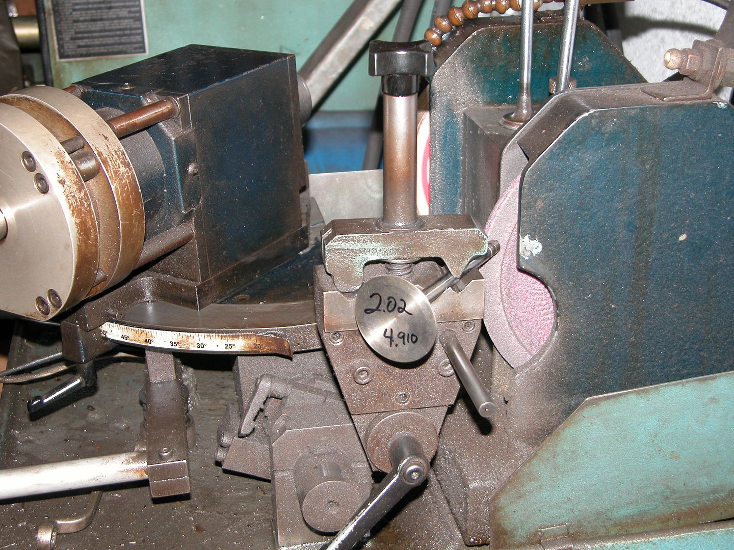
Cutting involves grinding the correct angle on the face that contacts the seat and then chamfering the top the stem and cutting the tip flat. For this engine 44.5 degrees is the angle of the face where it contacts the seat. Here's a pic of the machine we use. It's an older machine and we rotate the valve by hand to do the seat angle and the bevel on the tip. In the pic the valve is set for making the bevel on the tip which is done dry. The 44.5 angle on the head is made with the grinding stone on the other side of the machine and is done with lube that flows onto it while grinding. Forgot to get a pic of grinding the angle on the valve heads.
Cool build. What tranny will you be using?
Transmission is up in the air at this point. I've got an old 4 speed (which would be really cool) but no pedal assembly, flywheel, clutch or shifter. I've also got a T-400 (ready to go) but it has a Pontiac bellhousing and a C-6 for SBF I'd consider a core. I'm going to spread the word and maybe I can use them to sell/swap for something that will work well for me.
Same deal with the rear. I've got a couple rears but none set up with the correct mounts for the G-body. I'm hunting for an 8.5 out of one of the Turbo Buicks or 442's that came with them. The 7.5 with one wheel drive isn't going to cut it.
So with a set of valves ready now, it's time to check the valve guides. Shop technique for this is to put a valve through a guide and wiggle it to feel how much play there is. Then put a finger over one end of the guide, insert a valve stem till it hits the finger, then pull the valve out quickly to listen for a pop caused by the suction. After checking all of the ones in my heads we decided the valve guides wouldn't need to be replaced but needed a bit of work to tighten them up a bit. This is done with a "sipraler".
A spiraler cuts a groove into the inside of the guide without removing any metal. By deforming the metal it causes the inside diameter of the guide to be reduced and also allows a path for lubrication. After the spiraler is run through the guide a ream which is the correct diameter for the valve being used is then run through the guide. Both tools are run down from the top and drop out the bottom so the head needs to be up on stands.
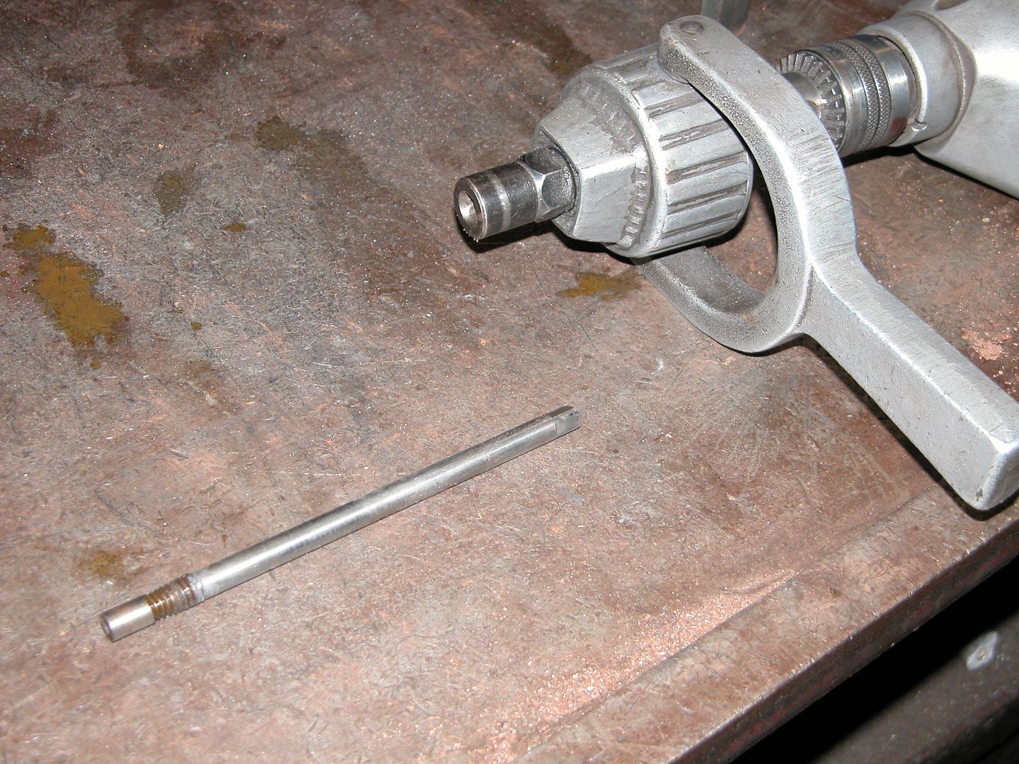
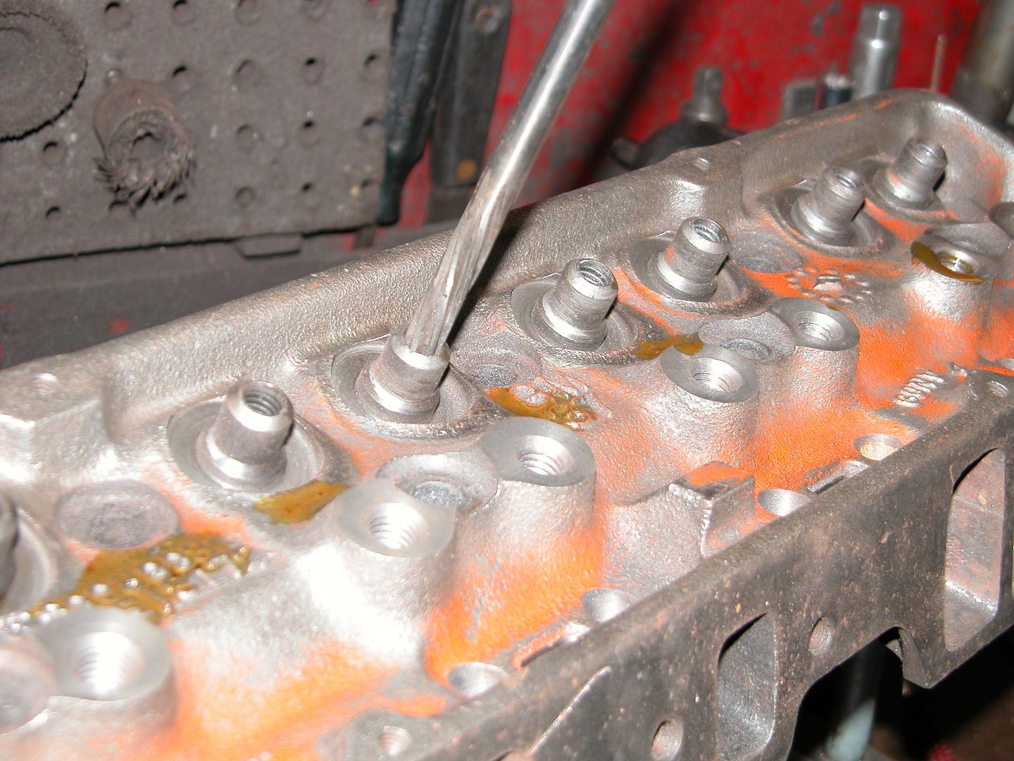
Pic below is a spiraler bit and a drill with a gear deduction so the work can be done at slow bit speeds. No pressure is used just the weight of the tool is enough. A couple drops of cutting lube are used during spiraling.
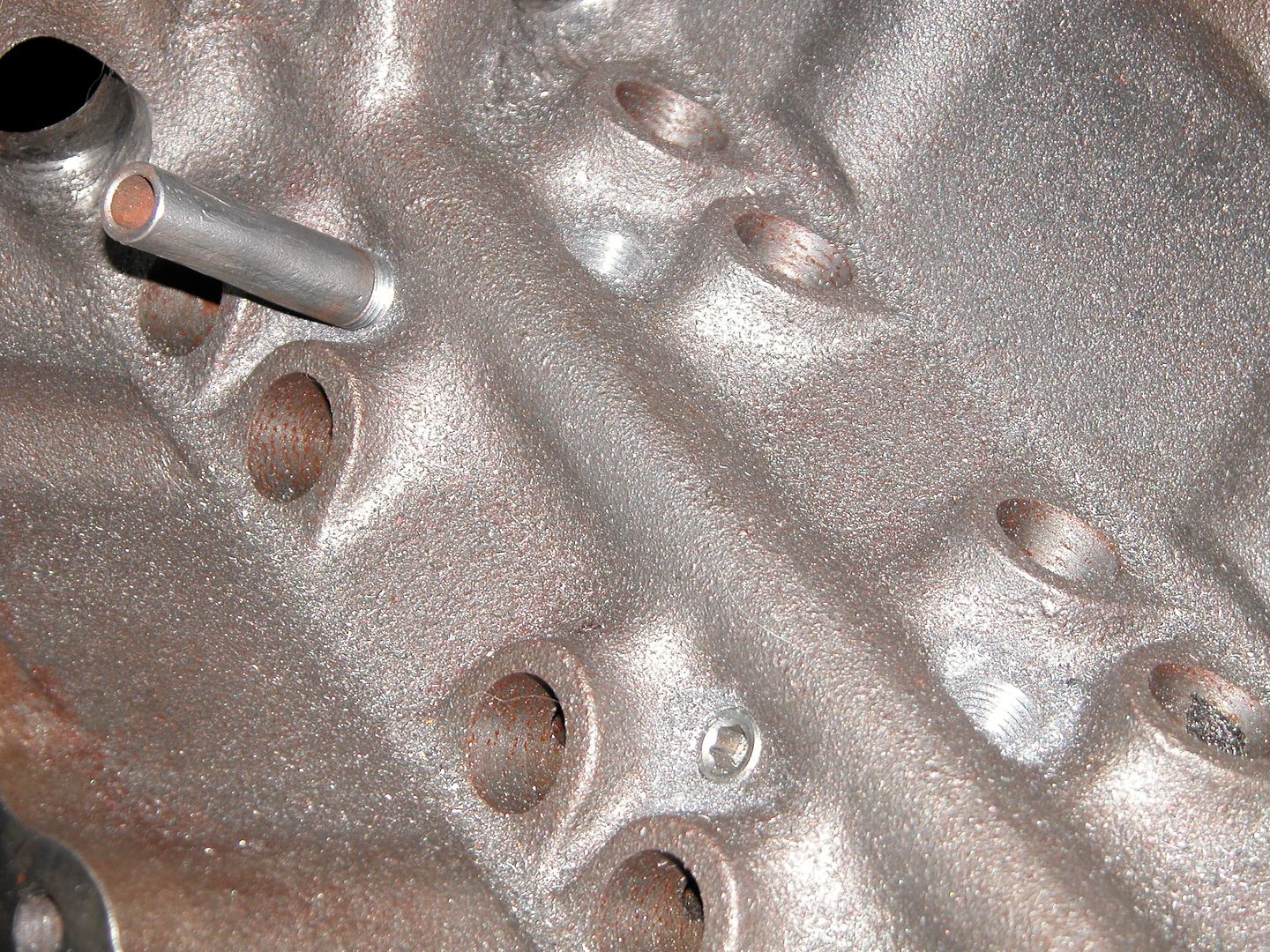
In the pic below you can see the grooves cut into the inside the valve guides by the spiraler and the ream being used to make the inside of the guide straight and the correct diameter. No more lube needs to be put in before reaming, whatever's left from spiraling can stay and is fine.
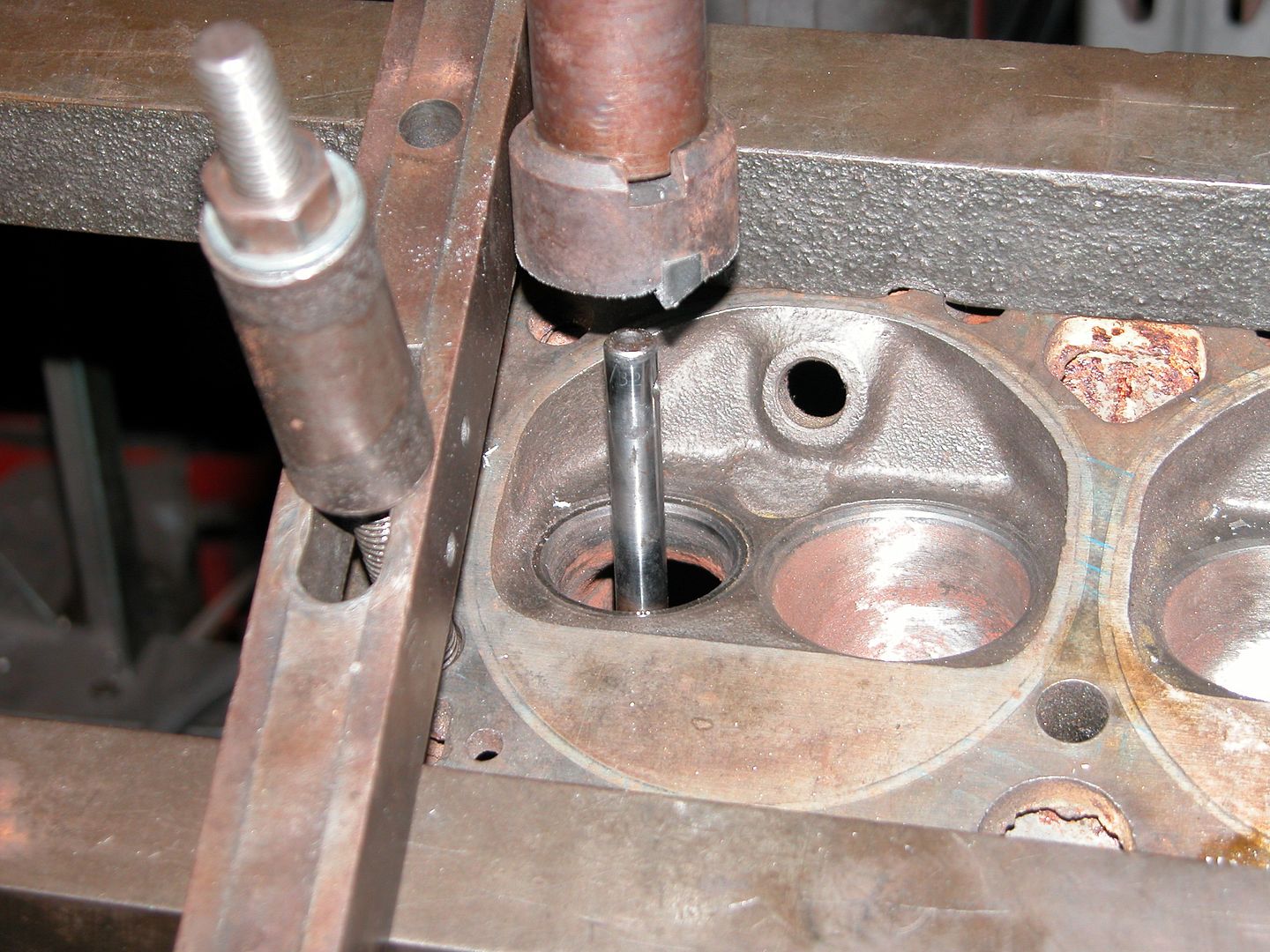
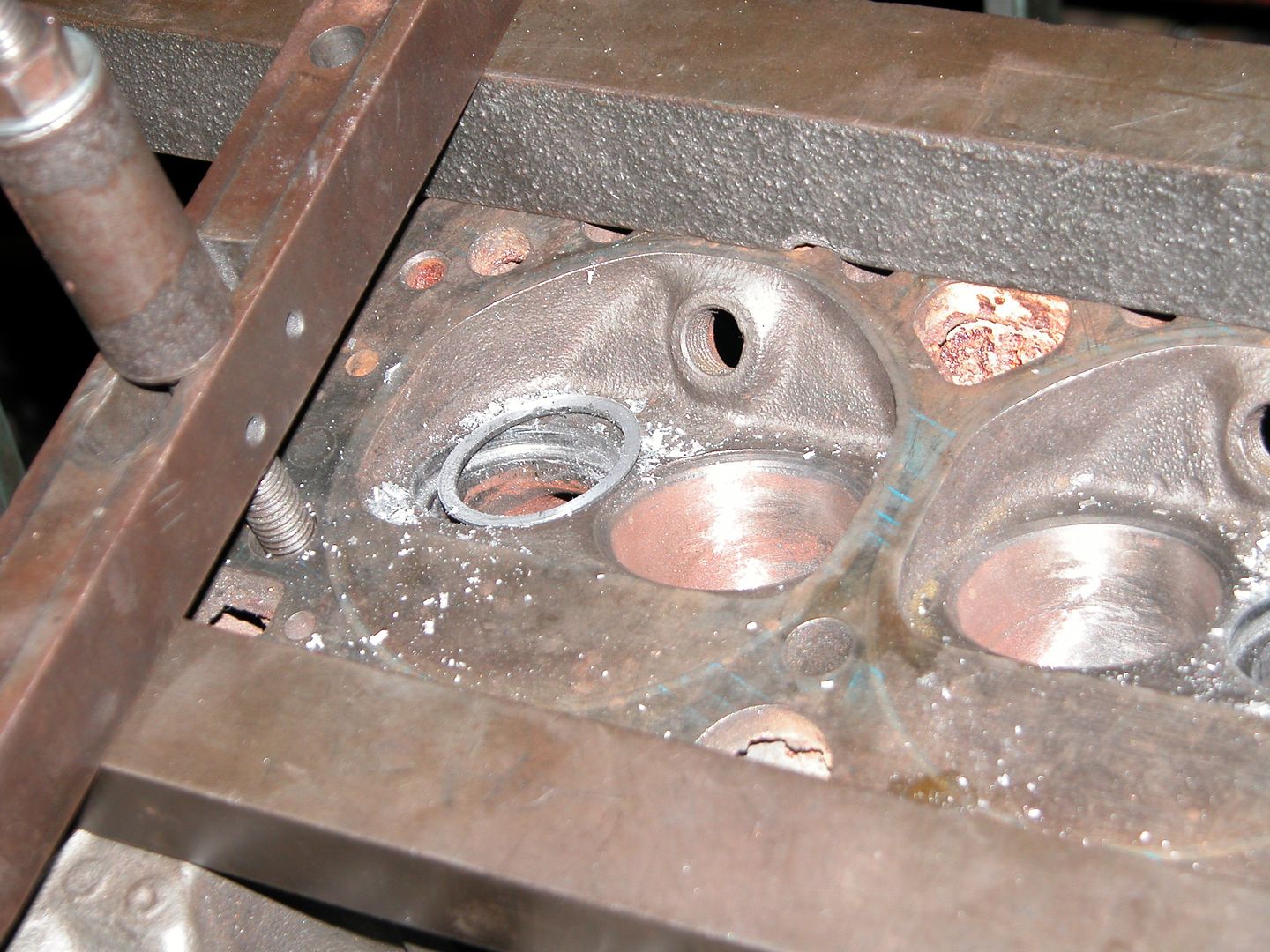
The head I found to replace the cracked one already had stock size exhaust seats installed in it at some point so they needed to be removed before cutting both heads for the bigger exhaust seats that will be installed. Seat removal is done with a cutting bit on the drill press. The head is mounted and leveled then the old seat is cut till just a very small amount of it is left which then spins freely and can be removed.
Here's a couple pics showing the cutting bit that gets lined up on the bit guide which is inserted into the valve guide and then the old seat after cutting and removal.
i'm glad you're back! love the machine shop explanations!

Pat
Reader
9/8/10 5:17 a.m.
Excellent posts! Thanks for sharing!
Glad you guys are interested! I find all the machining operations very interesting and am enjoying working/learning at the shop. I'm only posting machine shop operations related to this engine in this thread as I do them. If you want to check out some of the types of things I'll eventually post in this thread you can check out some posts I wrote about CCing combustion chambers, pressing wrist pins, measuring ring gaps, inspection honing cylinders, cam bearing install, hot tanking etc. in a thread I post random stuff I'm working on here http://allgentransams.com/forum/index.php?topic=1029.0 When I get to those steps on this engine I'll post about them in this thread. The other thread has Pontiac, BBC, SBC, and Mopar engines being used to demonstrate.
Anyway back to my treefityseven for Uncaged. Since we were out of the correct size for the new exhaust seats (and it was a holiday weekend) I jumped over to working on the block a little. I had scored a set of breather tubes for the lifter galley out of an engine I was stripping for scrap at the shop a few weeks ago. Someone had blown up something and swapped all their good parts over to a new shortblock and left the old one with the tubes in it. They're not the fancy looking aluminum ones but will do the same job so they're perfect for my no budget build.
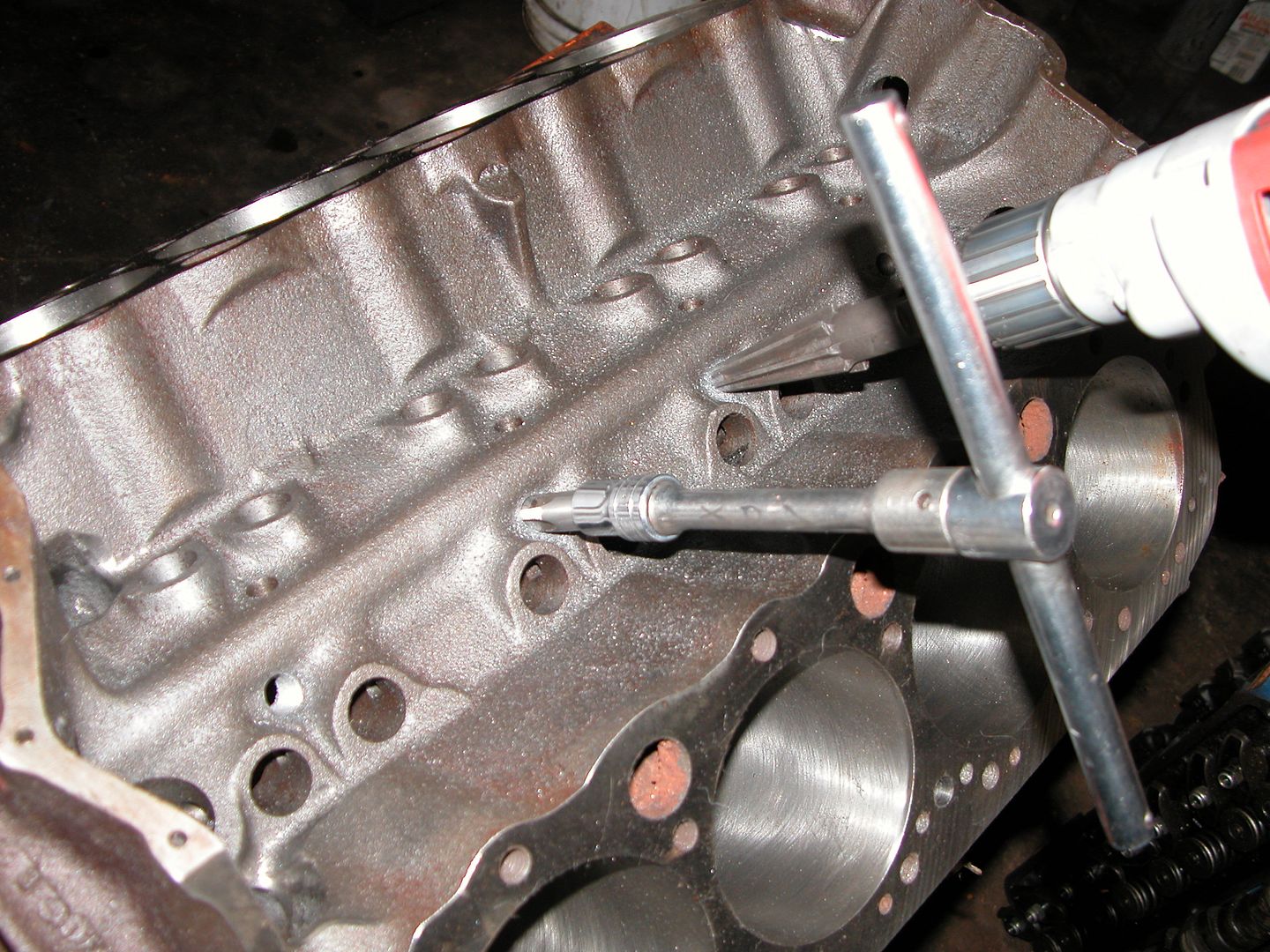
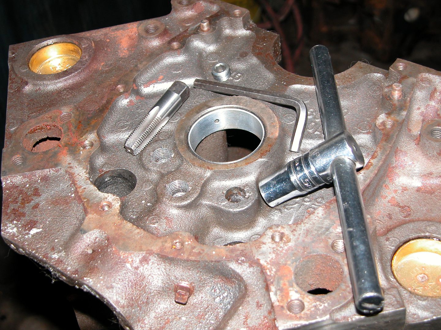
The block needs to be threaded in order to insert the tubes and plugs so while I was at it I threaded the end holes for plugs also. To thread the holes first a tapered reamer is used on a drill to chamfer the top of the hole so its easier to get the tap started. Then cut threads with the tap. Because these are tapered pipe thread the depth is checked on the first hole and then the tap is marked and the rest are tapped to the same depth.
Here's a pic of the reamer and tap . And then a pic of the vent tube and a plug. Bottom pic is the end of the block where plugs get installed.
This is great stuff: clear explanations with good pics to illustrate. Keep feeding us this stuff. Helps when dealing with a machine shop in the future. Thanks.
GM + Yellow Paint + Black Rally Wheels = Cool
TIGMOTORSPORTS wrote:
GM + Yellow Paint + Black Rally Wheels = Cool
Made my day TIG! I painted it Honda yellow back in the 90's. This time it's 09 Audi Imola Yellow. Did all the bodywork outside in a parking lot by hand.
A couple good questions popped up on another forum that might be of interest here, so I'm pasting it in below
[quote="1981Regal"]What do the vents add to the setup? Seems like its a weak point for the block. Just thinking aloud.
The vent holes are factory drilled. Installing vent tubes prevents oil from dropping through increasing windage on the crank so it's cheap horsepower by reducing parasitic losses.
[quote="Doober"]Is this a street motor? My understanding is vents are generally better left for race engines, and the extra oil on the camshaft helps keep it lubricated better for everyday street use.
I worked at the shop tonight and just happened to be decking SBC marine blocks so we had a discussion thanks to your question Darren. The concensus (of the engine builders) was that GM drilled the holes to vent the crankcase, not to provide oiling, and that the oil supplied to the cam and lifters was more than enough. Plus there's oil spraying around from the crank, rods and pistons. Having the holes blocked off gets the oil to flow down the holes in the corners and back to the pump quicker and with less aeration than if it goes through the vent holes and drops onto the rotating assembly, with the added benefit of cheap power. The factory probably didn't install vent tubes because it would require a threading operation, installation procedure, and additional parts. The additional power probably wasn't worth it to the number crunchers when comparing cost and potential liabilities to the power gain.
The street/race question concensus was that there is no down side to using the vent tubes so why not run them on the street if you're building a high performance engine. All the race engines built at the shop and most performance builds for the street or marine applications get vent tubes. Stock rebuilds for repair garages and "restoration" engines don't get them unless requested. Also it's generally accepted that not all of the vent holes are necessary for most SBC engines so many shops will buy a set of 8 and use them for 2 engines by installing a tube in every other hole and installing plugs in the other 4 holes. I took 8 of the cheap pipe style ones out of the engine I was stripping so I'll just use them all.
Im not necessarily a V8 nut, but this is a pretty damn cool thread anyway!
Bandit approves...
Bandit approved!! Cool! Moving along, I'm on to messing with pistons and rods.
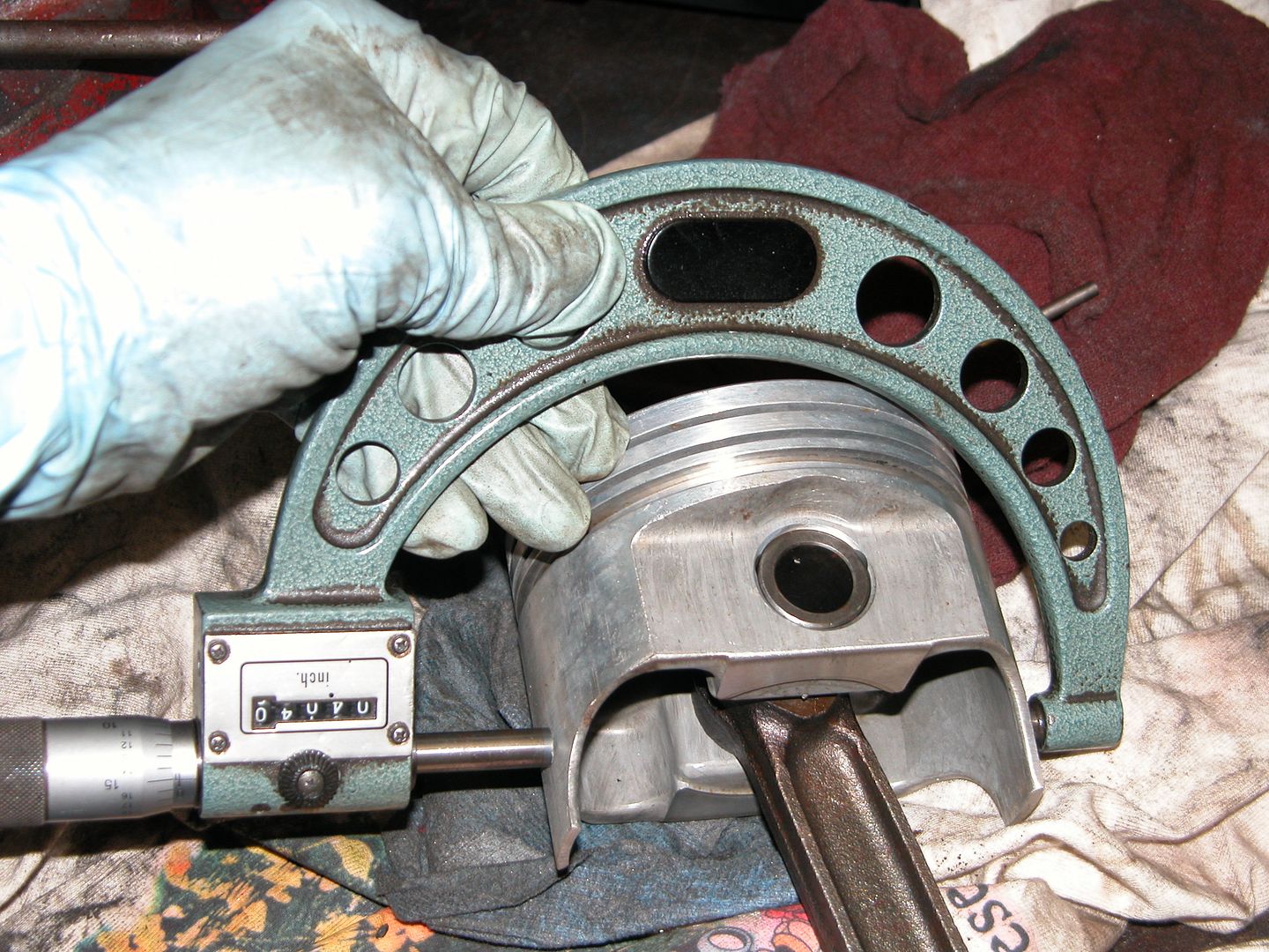
Since I was pressing wrist pins out of connecting rods at the shop I figured I'd get mine apart so they'd be ready for some work I want to do to them. The block had been bored to work with a slightly used set of .040 over forged pistons my buddy Mike at Mikes Automotive Machine in CT hooked me up with long before I moved south. It's been so long and with all the miscellaneous parts I've had and moves I made etc we figured we should double check the cylinder bores and pistons to be sure everything was going to work out cool. No sense taking the piston/rod assemblies apart if they wouldn't work. So here's a couple pics measuring things.
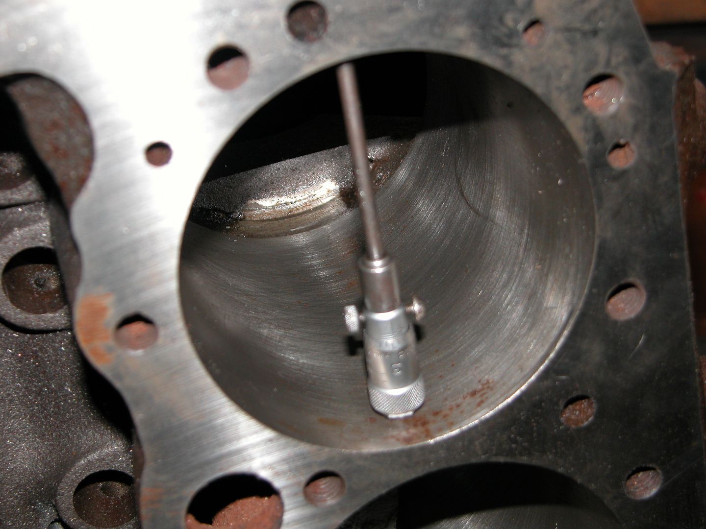
The cylinders came in at 4.041 and the pistons were around 4.0398+ so we'll be right in the ballpark of the recommended .0015+ gap recommended by TRW after the cylinders are honed. For the experienced/knowledgable guys I'm aware that these pistons were prone to cracking in the skirt curves when run too loose loose back in the day before they switched to the shorter skirts and I checked these. They were a gift so although they are an older design they're waaaay better than what I would have otherwise! Thanks Mike!
btw, I really like that body style malibu. cool project, but now that you are building the suspension and an engine, I suggest you paint it some faded metallic pea green color put some dog dog dish hubcaps on it and go hunting...
sleeper machine!
Need a trans and rear for that or it'd just break! LOL
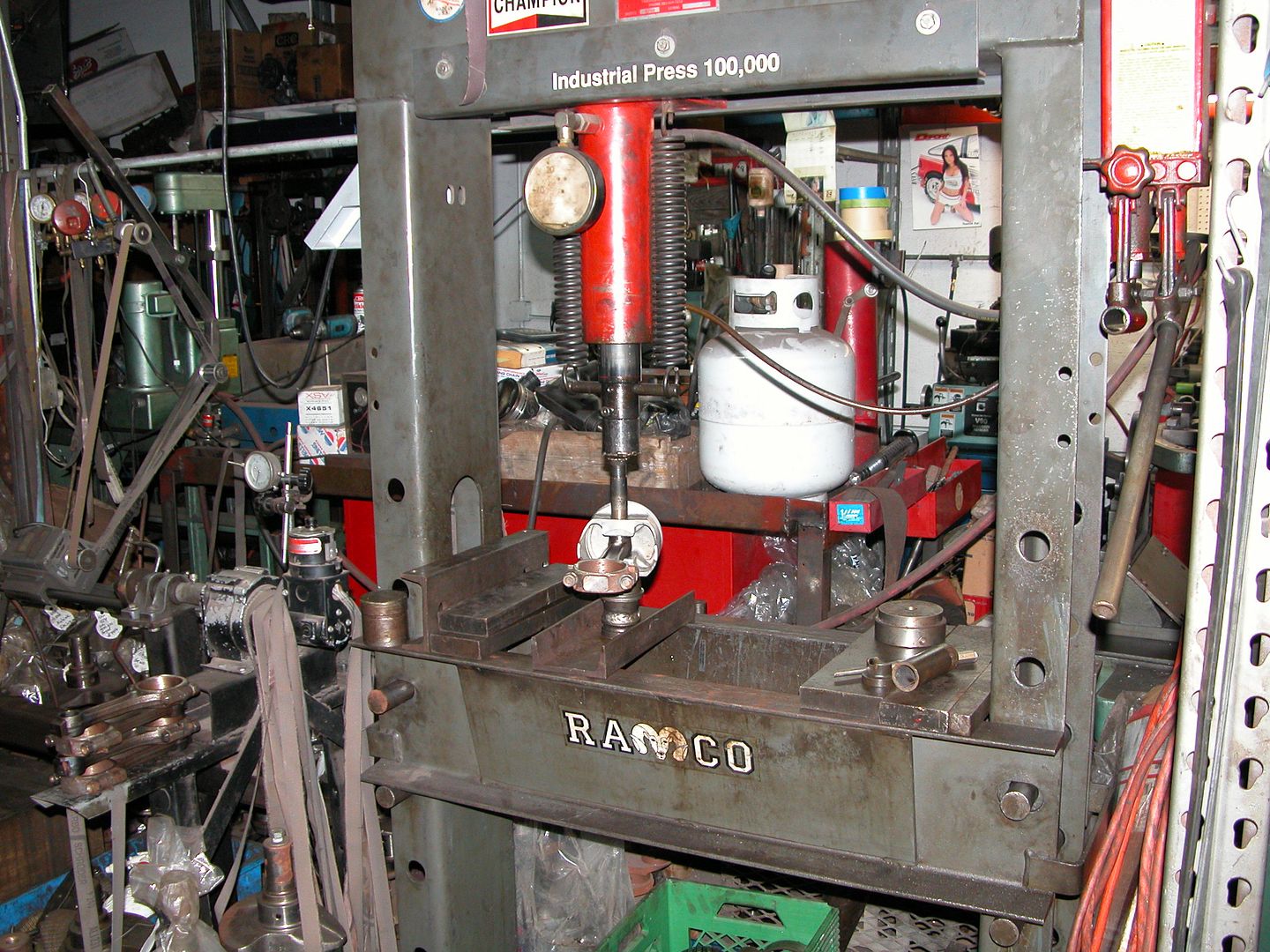
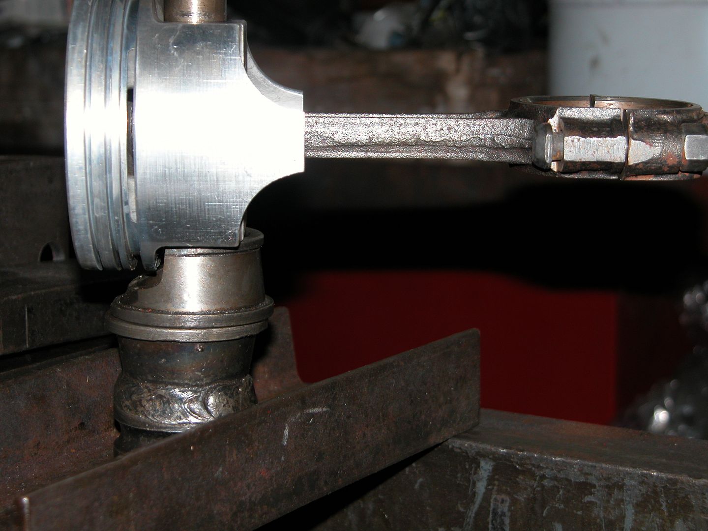
For those that have never seen it done, this is how we remove stock style wrist pins from piston/connecting rod assemblies. (Later on in the thread I'll show how they're installed)
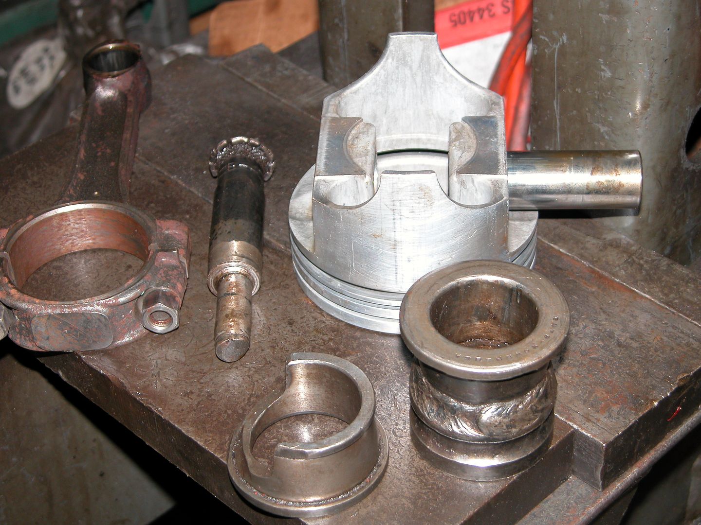
The pin is fitted with an interference fit in the top of the connecting rod and it takes a lot of force to push them out so a press is used. A support is placed under the side of the piston (different supports for different pistons) with a hollow base support below that to provide enough height to push the pin down. Then a tool that fits inside of the wrist pin with a shoulder that will push the pin is inserted. The tool is smaller in diameter than the pin so it will fit through the hole in the side of the piston. In the bottom pic the wrist pin is still stuck in one side of the piston but can be pulled out by hand. The "tight" fit is in the top of the connecting rod.
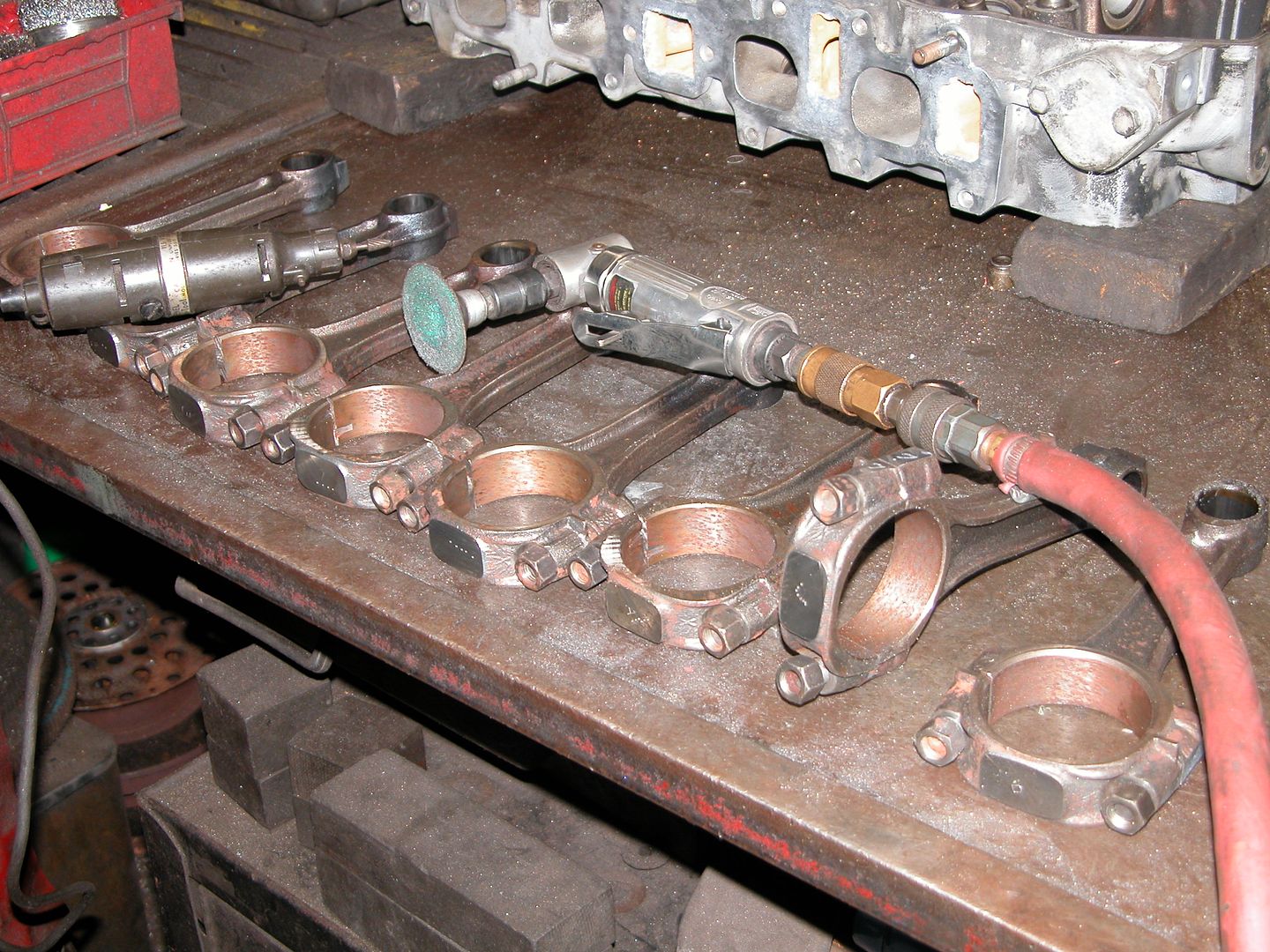
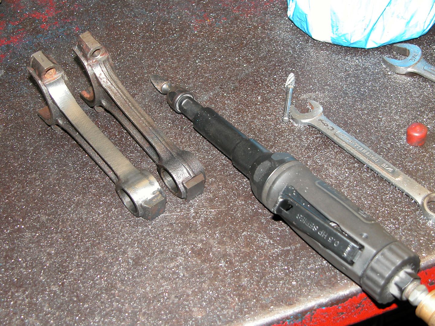
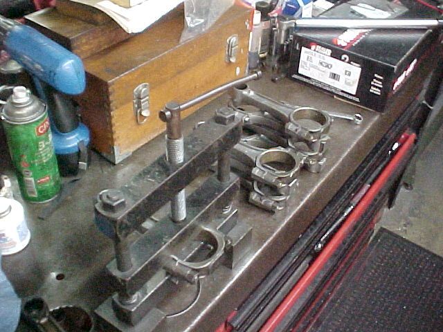
Shops mark things that are supposed to go in a particular place,order, or match up with machined surfaces.The rods had markings from other shops on them (in this case stamped letters/numbers and indentation dots) so I lined them up in order and did them the way we do them in this shop because I may loose some of the other markings as I work on them. I zipped the lock side of each rod with a disc and etched a number in each with a dremel. You may be able to see the 7 etched in the rod on its side and dots on the bottom of some of them. After that I removed the caps and bolts so I can start grinding them.
With the rods marked and disassembled it's time to start working on them. In this first step I'm using a carbide bit to grind away the ridge in the center of the side and blending into both ends. Care needs to be taken to keep rods even when viewing the sides not being ground and also not to remove too much material. The square "chunk" of metal at the top of the rod is left alone and will be ground a couple steps from now when I "balance" the rods. The bit in the tool is used for steel, the one on the bench for aluminum. The last person who used the air tool before me had been doing some welding repair work on aluminum heads.
There's a lot of awesome here.

In reply to Tom Heath:
Thanks Tom! Glad you're enjoying. Now If I could just move along a little faster! AHAHAHA
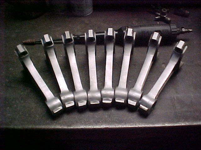
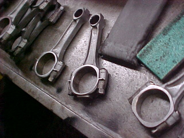
Anyway, today I finished up polishing the rods. After grinding the sides of the rods with the carbide bit, a sandpaper roll on a tapered bit in an air tool is used to smooth the grinding marks and then the rods are glass beaded. After that they're oiled down so they won't rust. It's not really oil, but a concoction based on tranny fluid. Pic below taken after glass beading and they don't look as polished as they do before blasting. Picture quality is lower now because my good camera decided to commit suicide and jumped off a chair onto concrete damaging itself beyond use. Hopefully it's repairable but until then the old camera is back in service.
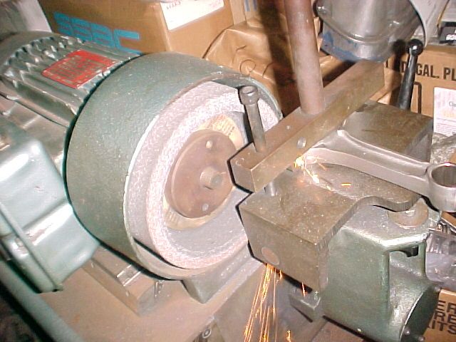
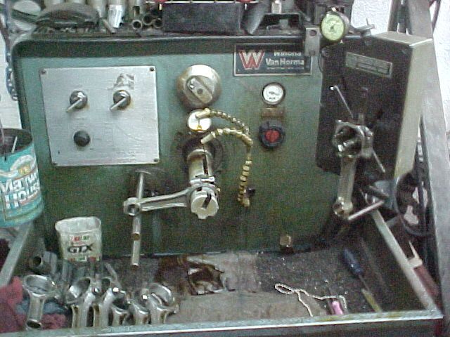
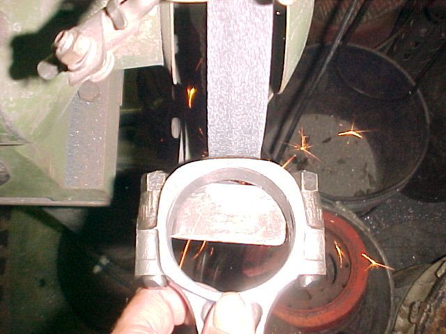
I started "reconditioning" the rods. First step is to make sure there's no burrs on the sides of the big end or where the caps meet the rod by running a flat file over them. Then the rod gets clamped into a machine that grinds a few thousandths off of the flat surface where the caps meet the rod. Then the caps are also ground flat on the surface that meets the rod. Here's a pic of one of the rods being ground. The rotating stone wheel is stationary and the rod is moved past the wheel while clamped square to the wheel in an arm thats moved by hand. I couldn't hold the camera far enough away while operating the machine to get the whole machine in the pic.
I cleaned up the rod bolts on a wire wheel. Next step is to reinstall the bolts for the caps. They are an interference fit so they need to be pounded into place. We have an aluminum block that gets mounted into a vice which has holes for the bolts to slide into. Then the bolts are installed with a 2 lb hammer and a large drift.
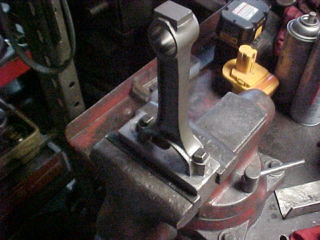
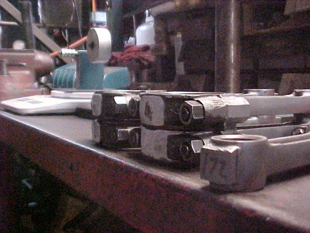
Once all the bolts are installed the caps that correspond with each rod are installed. The nuts for the caps need to be torqued to 45 lb. ft. so a special rod vice is used to hold them. The rod vice has wide machined flat clamping surfaces so no damage will be done to the rods working on them.
i love malibus...especially when they are yellow...my first one used to be yellow & black at one point of time
Great thread! Never heard of those vent tubes, I like it!
Thanks guys! Moving along......
Once all the caps are torqued the sides of the rods where the bearings fit in are block sanded with a coarse and then fine paper to remove any small burrs that have formed where the mating surfaces were ground and make sure the sides are nice and flatwhere the caps meet the rods. Then the rods are blown off and cleaned to remove any particles.
Once the rods are clean it's on to the honing operation! Since the mating surfaces of the rod and cap have been ground the hole for the bearing is now smaller than stock. This allows us to hone the bearing contact surface while opening up the hole to the correct diameter while being sure the enlarged hole is perfectly round.
Usually specs are checked (in a book) to determine the correct diameter of the hole needed for the rod bearings and then the gauge on the right side below is set with a micrometer. Because this is a commonly used size we have a SBC connecting rod we know is at "0" to calibrate the gauge instead of using a micrometer, just saves setup time. The hole will be made to stock size and the bearings will be ordered to make up the difference needed if the crank is turned down.
The size of the hole is checked on the gauge in the pic below where the rod is hanging. The hole is honed by stones spinning on a shaft while oil drips on them. The bar on the left holding up the horizontal rod keeps the rod stable while it is slid in and out (by hand) on the spinning shaft with the stones. Technique is required to get an even finish and desired crosshatch. In this case I'm opening the holes up until they are still a thousandth undersize and will take out the last thousandth after balancing and when the rods are cool so the measurements will be precise.
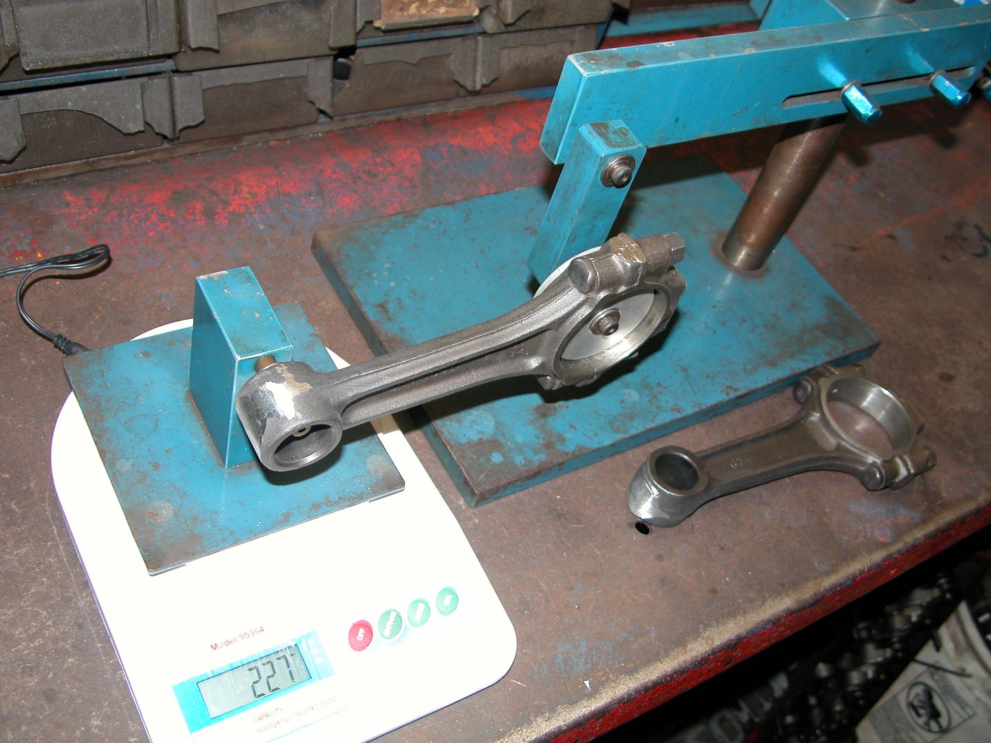
Time to "balance" the rods! This is done after honing because the weight of the big end of the rods may have changed depending on how much material was removed grinding the mating surfaces and then honing the end.
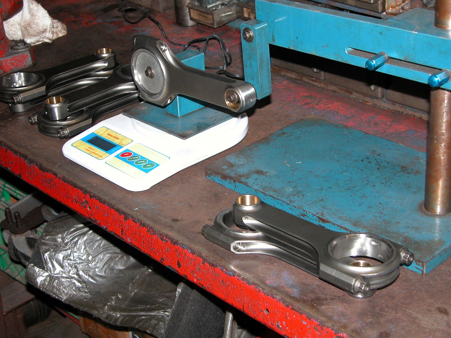
Each end of the rod is weighed using a digital scale and the balancing apparatus shown below. An adapter that closely matches the diameter of the big end is used on either the stationary pivot or the floating pivot on the scale depending on which end you're weighing. The weight of each end is marked on every rod.
Starting with the heaviest "big end" rod the square chunk of metal on the end of the rod is ground down on the rods that are heavier than the lightest one. After they were all down to the weight of lightest one I examined to see if they could all be lightened a bit more without sacrificing durability and took a couple more grams off of each one. The same procedure was then performed on the small end of the rods.
They're now all at 414 and 169 grams. Not super light "race weight" but now they're lighter and equal weights. Less weight allows the engine to "rev" more quickly. Do I really need polished balanced rods for this engine? Probably not, really. LOL But it's cooool!~ AHAHAHA And I have a full shop at my disposal, so why not? As with anything, different customer requests, applications, and products may use different procedures so YMMV.
It was about 3 AM when I was doing this and I forgot to take lots of pics, so the first 2 showing the equipment used are pics I had from other peoples projects lready completed and the second 2 are my rods.
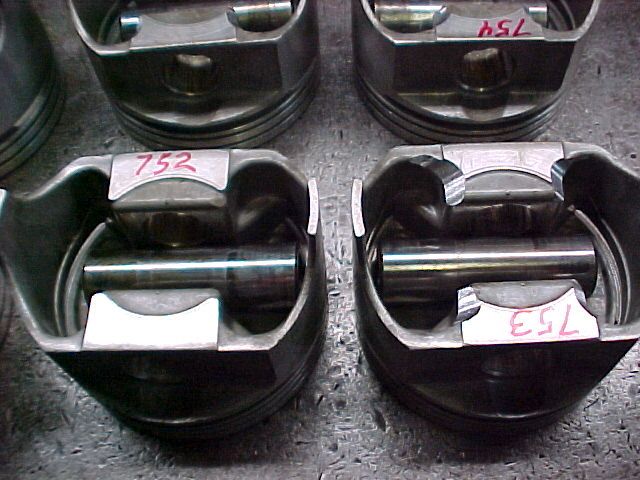
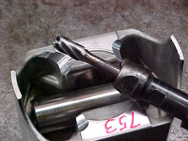
Had a few minutes last night after decking blocks so I got my pistons out and weighed them for balancing. They ranged from just under 752 to 754 grams (with corresponding wrist pins). Tonight I ground away some material by the wrist pins on the heavier ones to bring them down to 752. I could have milled the inside of the top of the piston to remove the weight but for this engine the extra time and effort required isn't worth it.