As winter drags on I've got in my head a bit of a brain teaser I wanted to play with.
My idea was to play with creating a modified geometry steering knuckle. The early hurdle I'm running into is measurement accuracy of the original part. I'm particularly struggling with how to wrap my head around accurately locating holes on multiple different planes relative to each other starting with a blank sheet of paper.
My initial thought was 3D scanning of the knuckle. A bit of research shows that might be cost prohibitive? What does the HIVE have to say about accurately locating features of a part like this? Really all I'm concerned about are the location or centerpoint of all the holes. I can fill in the blanks around that I think.
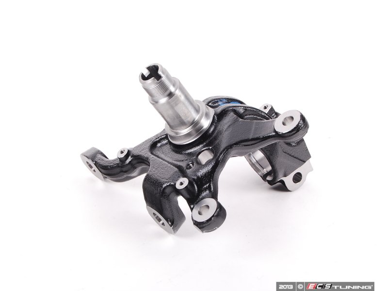
pictures for posterity:
SEMA offers 3D scans and FARO measurements as a service. The cost is not prohibitive, but it will cost money.
Heck, we've got a 3D scanner of our own. Not that our engineer uses it, but it's a cool toy.
3D scanning isn't ruinously expensive anymore, but you could expect to pay $100~$200 to get something of that size scanned. You'll still have to mark the hole centers but it'll be much easier to do on the computer.
You could measure the relative distances between the holes yourself at home with just a sheet of graph paper, common measurement/drawing tools and some kind of rig to hold the upright flat and in place.
3d scanning will not be accurate enough. You want a CMM.
I can measure it for you if you send me the part. I have both a CMM and a Faro arm, but I would use the CMM.
Send me a PM if you want me to do it. Goes without saying that I will not charge you, you just pay shipping both ways.
Call around to your local fab shops. Someone will likely have a coordinate measuring machine. Maybe they'll measure it for you for a few bucks.
Edit: Too slow...
Gameboy, I was thinking that I could rig something up to hold it square and then plot my out to the holes from there.
I like Slippery's idea of a CMM. PM incoming sir, thank you for the gracious offer!
edit: that's also a fair bit cheaper than I had thought 3d scanning was after a quick google search, I'll have to bear that in mind for future reference.

DrBoost
UltimaDork
1/10/17 12:05 p.m.
You can download apps that turn many photos from your phone into 3d scan. You can also use an x-box (IIRC) to build a 3d scanner. But I agree, CMM is the way to go.
CMM all day. Scanner are neat but you need accuracy not a point cloud,and how can you beat free ?
Our scanner is pretty precise, certainly enough for this use. But it's not free 
The price is right for the CMM but playing with a 3D point cloud is something still to be added to my bag of CAD tricks.
Depending how far I go with this Keith I may have to give you guys a call. For now the CMM data should more than suffice, but in the future....who knows!

I have done some 3D scanning at work with some 'real' scanners in addition to the xBox solution, to try to understand if these tools would be useful for us. While it is quite possible to create some representative geometry, you would not be able to simply take the point cloud and assume it is accurate. A CMM is definitely the right tool for the job. However, had there not been very generous offers from other members, it would be possible to take the representative point cloud of the casting and spindle and add actual CAD geometry of the ball joint tapers and the spindle itself. That would give you accuracy where you need it (ball joint locations and spindle) and a representative model within an mm or two where you don't (the casting itself). You would still need an accurate way of measuring these locations relative to whatever datum you are using, though.
EDIT: also, while I do enjoy CAD work in general, dealing with point clouds and scan alignments and such is kind of a pain, in addition to being quite time consuming for a minimally skilled person such as myself.
It would take a bit of time but I could put that in to a 3d cad file by just measuring off a fixed point. At my hourly rate it would probably be cheaper to see is someone else has already made a spindle that you can use.
I have done that in the past with other suspension parts. Tediously slow and boring work but you end up with somthing that a good machien shop can make.
I recently modeled a M62 rear housing to see how to then make a mounting brackets for it for my Porsche.
Probably beyond the scope of this project, but my company (Siemens) just introduced some new CAD technology that allows you to do a 3D scan and get real data that you can use and modify: Convergent Modeling.
Tom_Spangler wrote:
Probably beyond the scope of this project, but my company (Siemens) just introduced some new CAD technology that allows you to do a 3D scan and get real data that you can use and modify: Convergent Modeling.
Awesome. We just got NX9. It'll probably be 2020 before IT upgrades us to 11 :(
CMM/Faro Arm/Etc. is definitely the right answer here. That said, I've experimented a bit with some home 3D scanners a bit:
DIY 3D Scanning 1
DIY 3D Scanning 2
Man, I really need to follow up on this stuff.
Is this for a custom pet project, or a commercial enterprise?
If the former, how much accuracy do you really think you need on locational tolerances? Certainly not .0001 inch, or even .001 inch. And honestly even .01 is probably overkill. Mass production tolerance stack ups are way worse than that, and that's not even counting all of the impreceision and deflection in the rubber mounting of all the suspension components. A caliper, an angle finder, a straight edge, a little imagination, and a bit of time can probably get you more than adequate GRM results. Just for giggles, I'd also consider experimenting with the DIY multi-photo 3D 'scanning' to see if it can get acceptably close on the main feature geomtery. Getting more precise bore measurements, which can also be done manually, is going to be more critical than than locational precision...Not that I would turn down free CMM measurements either though.
If the latter, you've got to pay to play.
There are scanners out there that rival CMM accuracy; we have one at work. A very good scanner (GOM) + Geomagic XOR software can give you capability to completely reverse engineer a part. For what you are looking to do something like a FARO arm could give you the relevant geometry that you need to determine suspension characteristics.
That's my thinking - while a 3D cloud isn't as precise as a well executed CMM, it's precise enough for what's going on here. I'm assuming a real scanner, not some weird Xbox or phone setup. If you have access to one, it's a good enough tool for this. As with anything else, it has to be well wielded.
I once had a very confident fellow borrow a Miata subframe to measure up. Loads of boasting about how flat his table was, how much he'd spent on the equipment, how this would be the more precise measurement ever possible, etc. He was quite aggressive about it. When he sent me the drawings, you could SEE that one of the points was 3" off. Didn't have to double-check, he'd failed the basic eyeball check. Wow, did I get chewed out for that because it was somehow my fault. Since then, I've not trusted any outside dimensional information unless it's from the manufacturer.

tuna55
MegaDork
1/11/17 10:04 a.m.
CMM alone is not going to find all those important measurements which avoid having the knuckle crash into everything around it, though it will do a great job iof getting the points you want.
3d scanning is a great tool for this.
We can even print it in metal, though that is quite expensive.
In reply to tuna55:
Most knuckles are simple sand castings with at best a .060 tolerance on any given feature. Hell, 5-Axis CNC machined aerospace components regularly have at least .040 tolerances on non-critical features. I bet you'd be hard pressed to find any non-machined surface on a knuckle casting with less than .100 minimum clearance away from 'crashing into everything around it'...And even if you did, the loving caress of an angle grinder would fix it real quick.
Even on machined parts: The tighter you hold the tolerances, the more expensive it gets. As such, there is absolutely no point in measuring (or designing) something to an order of magnitude tighter tolerances than it realistically needs to (or is actually going to) be manufactured within. Kind of like the engineer that carefully integrated a large radius gently sweeping arc across a part feature, only to have it turned into a flat face (within tolerance) by the machinist.
tuna55
MegaDork
1/11/17 11:26 a.m.
Driven5 wrote:
In reply to tuna55:
Most knuckles are simple sand castings with at best a .060 tolerance on any given feature. Hell, 5-Axis CNC machined aerospace components regularly have at least .040 tolerances on non-critical features. I bet you'd be hard pressed to find any non-machined surface on a knuckle casting with less than .100 minimum clearance away from 'crashing into everything around it'...And even if you did, the loving caress of an angle grinder would fix it real quick.
Even on machined parts: The tighter you hold the tolerances, the more expensive it gets. As such, there is absolutely no point in measuring (or designing) something to an order of magnitude tighter tolerances than it realistically needs to (or is actually going to) be manufactured within. Kind of like the engineer that carefully integrated a large radius gently sweeping arc across a part feature, only to have it turned into a flat face (within tolerance) by the machinist.
No doubt the tolerances are generous, but I am saying that things like wheel and caliber clearance along with the steering stops and other features will take a lot of point gathering with a CMM, whereas you can just grab a 3D scan of the whole thing and be done.
Either way he'll be fine, it's just my preference.

Driven5, this is just a pet project, lowering spindles were a fairly common modification for c5/c6's in the group I play with, but nobody seems to make anything similar for the BMW's otherwise I always prefer the off the shelf solution. The roll center correction kits that are offered come in the form of extended balljoints and I've seen enough of those fail if driven over kerbs that I don't fancy putting them on my car.
Tuna55 I agree, not a simple modeling project from CMM data but I didn't expect it to be. From the baseline geometry and setup side of things the critical items in my mind are accurately locating: the lower ball joint, tie rod end location, the strut mount and the caliper mounts. Other features like the ABS sensor hole and it's distance from the hub etc are important but can be factored in later. From there I can fill in the blanks. A placeholder for the rotor is easy to draw, calipers again not too tough (heck grabcad may already have a 6 piston brembo caliper I can start with) Wheel model place holder I can create as well.
I was really struggling with a way to accurately reference the holes from each other in so many different planes (a bit different than the work I'd done in the past with differentials everything is concentric) and I think the CMM will do that admirably and then I can fill in the knuckle shape around it. As my method of producing a pair of hubs for myself would be machining from blocks of material the "improved" design will likely look a bit more simplistic than the OEM cast piece like so:


grpb
Reader
1/11/17 12:18 p.m.
Without the corresponding control arm hardpoints and inner tie rod end locations, as well as actual centers of the balljoints/rod ends you can't do too much with just the knuckle itself.
But if you're willing to put in the time you can get most of that with a relatively flat surface, plumb bob, squares of different sizes and tape measure, assuming you're willing to disassemble the front end to get the measurements. Use paper/pen and plumb bob on the flat surface to get lateral/longitudinal (relative to defined and repateable centerlines) and the tape measure to get verticals. Having some steel balls of different sizes can help get the verticals for approximate hole heights.
Any machinist with a granite and appropriate fixturing/ gaging could get the knuckle hardpoints, but that doesn't help for chassis pickup points or balljoint centers relative to their mounting in the knuckle.
It's not CMM, but it's cheap and gets you ALL of the information you need to look at suspension geometry.
Anyway, once it's time to modify anything physically, you're still limited by the same ability (or inability) to measure/fixture the things you want to modify.

NOHOME
PowerDork
1/11/17 12:25 p.m.
Quick search on the Googles brings up a lot of existing CAD files for steering knuckles.
https://www.pinterest.com/pin/291537775857411619/
One of the great advantages of Solidworks is that there is a bunch of "parts" files that you can just import as a part of your assembly. You don't mention what drawing package you are using.
grpb wrote:
Without the corresponding control arm hardpoints and inner tie rod end locations, as well as actual centers of the balljoints/rod ends you can't do too much with just the knuckle itself.
But if you're willing to put in the time you can get most of that with a relatively flat surface, plumb bob, squares of different sizes and tape measure, assuming you're willing to disassemble the front end to get the measurements. Use paper/pen and plumb bob on the flat surface to get lateral/longitudinal (relative to defined and repateable centerlines) and the tape measure to get verticals. Having some steel balls of different sizes can help get the verticals for approximate hole heights.
Any machinist with a granite and appropriate fixturing/ gaging could get the knuckle hardpoints, but that doesn't help for chassis pickup points or balljoint centers relative to their mounting in the knuckle.
It's not CMM, but it's cheap and gets you ALL of the information you need to look at suspension geometry.
Anyway, once it's time to modify anything physically, you're still limited by the same ability (or inability) to measure/fixture the things you want to modify.
A friend and I are both in the process of pulling apart the front ends of our car and getting measurements of the various other bits needed to calculate the geometry. As we're about 3 states away we figured 2 sets of measurements should allow us to catch any errors and ensure we're being accurate.
I'm not sure why I was having such a mental block on the knuckle you guys are listing out some great ways that I could do it were it not for Slippery's generous offer.
Nohome, I'm planning to use solidworks for the modeling and Catia V5 for FMEA analysis.
Just wanted to give an update:
This project is still ongoing! Slippery has wrapped up measuring all the critical features and gotten a CAD file together with those dimensions so now I can play connect the dots (the 3D version)
Besides filling in a complete knuckle from the relevant data the other next steps will be measuring the cars current front roll center, bump steer, and dynamic camber change.
I'll gladly keep updating this post as I progress if folks are interested?


