tough photos....


After working these photos... are these all intakes? Some appear to be smaller then their opposing valves.....
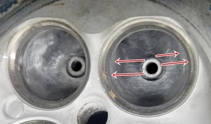
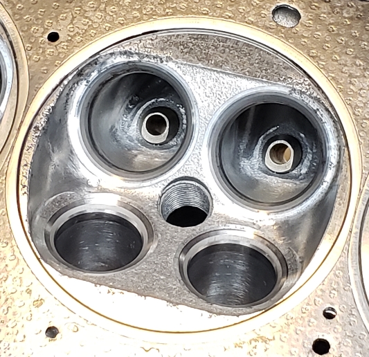
Anyway, there does appear that a few of the bowls were poorly cast (dotted lines) The arrows are pointing out areas that should get blended back, especially after you have checked/set the ID of the throats.
The two smaller are exhaust, larger are intakes. I tried to take two clear pictures of the worst (visually) port to give an idea of what I have.
The troat id: 85-90% and as round as possible, correct? Just trying to get a good feeling for what I am doing as i want to learn.
In reply to oldeskewltoy :
That RBB head looks grody, but the castings look pretty dang good for an OE-delivered port!
Dusterbd13-michael said:
The two smaller are exhaust, larger are intakes. I tried to take two clear pictures of the worst (visually) port to give an idea of what I have.
The troat id: 85-90% and as round as possible, correct? Just trying to get a good feeling for what I am doing as i want to learn.
Assuming intake valves are are 33.25mm intake, and 28.75mm exhaust (2.0 DOHC). Work the intake seat until the ID is 28.25mm, and the exhaust to 24.5mm. (Both measurements are roughly 85% of their valve). After the ID of the seat is set, blend in the bowl, blend in the short radius.
In reply to oldeskewltoy :
So, just to make sure im understanding: the steel pressed in insert is the seat. The vertical portion behind the valve angle is what we are calling the seat that we will be working. The aluminum behind that is the bowl. Right?
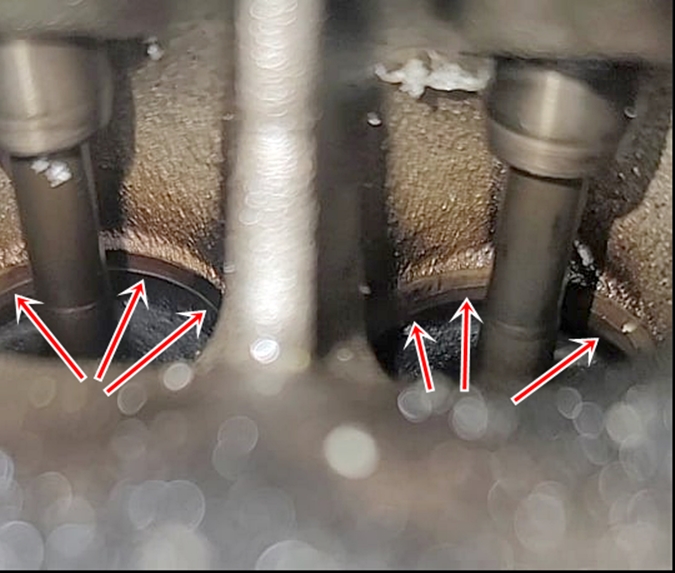
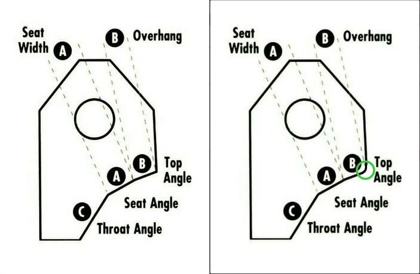
Not sure this will help.... as you mentioned they(cut-aways) didn't make a whole lot of sense to you.... hoping you might "see it" a bit better....???
(edited - replaced photo)
Red arrows - exhaust short radius
Red dotted lines - exhaust area for material removal
Blue arrows - intake short radius
Blue dotted lines - intake area for removal

Dusterbd13-michael said:
In reply to oldeskewltoy :
So, just to make sure im understanding: the steel pressed in insert is the seat. The vertical portion behind the valve angle is what we are calling the seat that we will be working. The aluminum behind that is the bowl. Right?
The pressed in steel is the seat....
"The vertical portion behind the valve angle is what we are calling the seat that we will be working" - ??
The bowl is the area from the front edge of the guide all the way back to the steel seat
That makes perfect sense now!!
Thanks!!!
Do i do anything with the valve guidea?
Dusterbd13-michael said:
That makes perfect sense now!!
Thanks!!!
Do i do anything with the valve guidea?
has a machine shop (or you) checked the guides for excess wear?
if they are good... leave them.
Last, before you work the port exit/entrance hang your gaskets and check for clearance. No reason to have a gasket hanging into the airstream
This is a single intake port. Blended the valve seat, opened the short side up, port matched. Like i think your diagrams were showing. I don't have an accurate way to measure the throat for percentages of valve seat, as i cannot seem to get repeatable measurements.
Also, im doing this all with a dremel. I got flap wheels for it, and sanding rolls for the drill.
Im also trying to take pictures like you do, in the hopes it helps for apples to apples comparison.
Im a noob. Please criticize and critique. Yoh won't hurt my feelings, and i know that it can be better. Just not how to get there.... edit for more pictures


Sorry... been kinda side tracked.....
Dremel sanding mandrel 1/2" and 1/4" along with 1/2", and 1/4" sanding bands. Coarse for larger material removal, Medium(or fine) for finish work. 1/4" works well on the side of each bowl (area on either side of guide)
As far as your pics... 1st has a bit too much light... others look mostly ok. I would recommend a reliable caliper....
Hey Oldeskewl.
I'm looking to get an L28 head rebuilt / posted and polished. What's the best way to contact you?
birdmayne said:
Hey Oldeskewl.
I'm looking to get an L28 head rebuilt / posted and polished. What's the best way to contact you?
oldeskewltoy@yahoo - you know the rest.
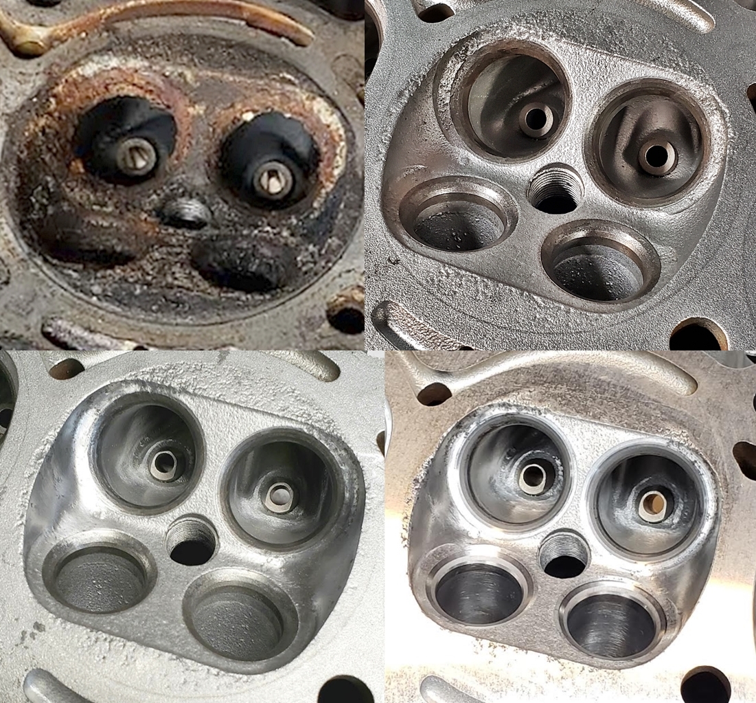
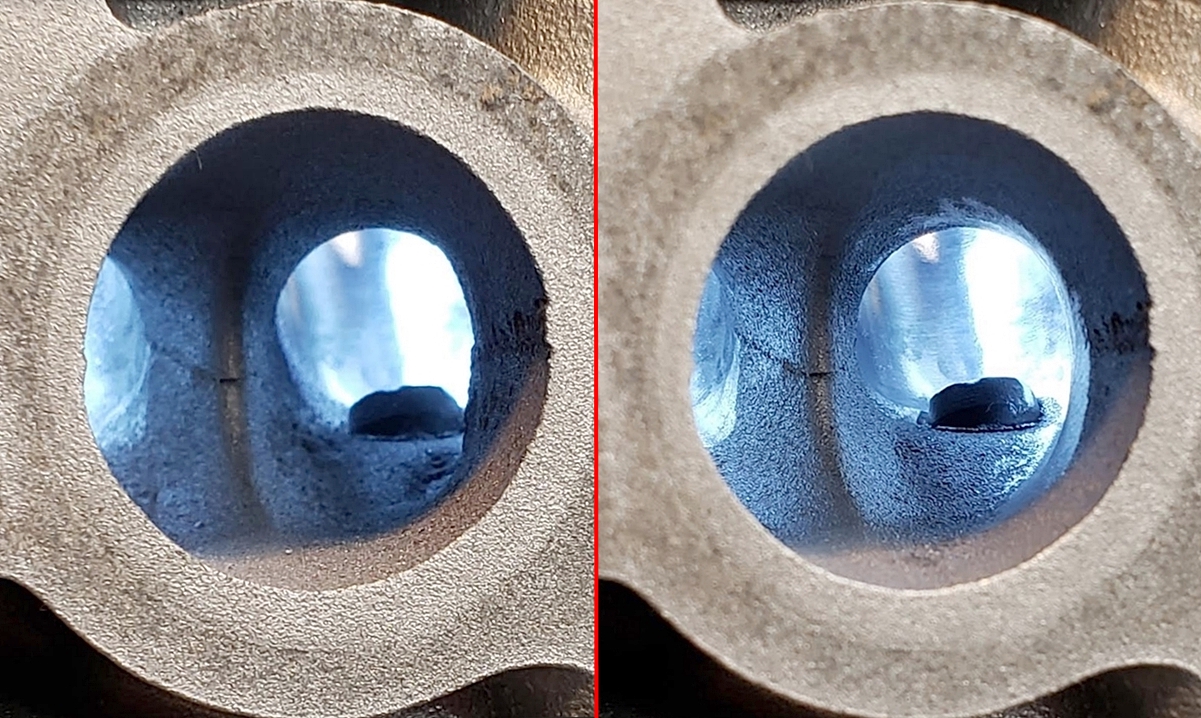
This doesn't look all that bad... although it is a bit coarse

This short radius shows less than ideal (smooth) transition. Also a bit more material can be removed on the splitter wall

This bowl appears to have more room on both sides of the guide
a 4AG head with HORRIBLE seat - bowl alignment.
This can't be overcome except if it is used as a core for a big valve head
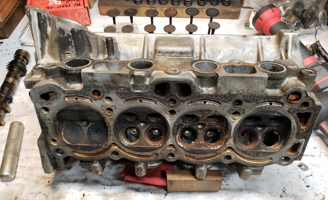
Fixing other issues.... PLEASE... store your stuff better then this guy stored his......
Chamber 3's progression....
With gasket fitted... no damage at, or beyond the fire ring. Lapped in the valves to make sure the seats are sound
This chamber came real close to needing welding, and reshaping....

 this is the first exhaust port ive done. Needs final sanding work, but i think it is close. what are your thoughts?
Also, i put valves in to see about valve shroud. Should i work on deshrouding? Or am i better off not touching the chamber? Looks like theres an aluminum lip from the surface of the chamber to the steel of the seat, but it also looks like the valve is proud of the surface of the chamber. Not sue what, if anything, i should do here.
I really appreciate all the help so far, oldskooltoy. Really appreciate it. Im feeling good about my porting work for the first time.

There is little or no need to work the port floor, but you can work the port walls, and the roof a bit more if you do choose.
What is the ratio between valves diameter(OD), and seat/bowls (ID). It looks like it is still under 85%? Did you get a caliper yet?
As far as deshrouding, I'd talk with your machinist and see if they have a 3 angle cutter with a deshrouding edge - note difference in cutter edge (below) Radius at the outer edge of the cutter


mke
Dork
11/22/21 1:00 p.m.
I like this one from goodson. It has the radius on the outer edge and flows pretty well on most any head.

I THINK im doing the measurement and math right.
I ised my calipers to measure the throat of the valve seat like so
 i then used the other set of calipers (i guess thats what they're called? inherited a set of them like this) to find the tightest spot in the port pre divider wall widening, and measured the spread with the same calipers.
 then divided the smaller number by the bigger number coming up with .931
Which means i opened the port to 93% of valve opening at the tightest bowlto port point.
An i doing this right?
Dusterbd13-michael said:
An i doing this right?
not what I'm describing......
This is correct....
.... and this would be the other measurement

In reply to oldeskewltoy :
Ah. Ok. Doing that, i wind up with throat diameter of 26.2 and valve head diameter of 30.5 for .85
In reply to oldeskewltoy :
So does my port measurement bear any relevance to anything? Im hoping it doesn't kill velocity.
Also, the chambers: should i smooth down the sharp lips around the valve seats to aluminum head surface, and try to allow a little more air through the valve opening gap? Or am i borrowing trouble?
Dusterbd13-michael said:
In reply to oldeskewltoy :
So does my port measurement bear any relevance to anything? Im hoping it doesn't kill velocity.
Also, the chambers: should i smooth down the sharp lips around the valve seats to aluminum head surface, and try to allow a little more air through the valve opening gap? Or am i borrowing trouble?
85%-90% is what these throats are typically set at, so 85% would be considered higher velocity. As far as blending the chamber into the valve job - this is NOT an easy task it typically requires a moderate level of skill(practice)... and it is usually performed after the valve job.
Just a few passes at the right place inside the port gets me 75% of the way
Big valves, require a big exhaust port.


