1 2 3 4 ... 13
oldeskewltoy
oldeskewltoy SuperDork
5/31/14 1:18 p.m.

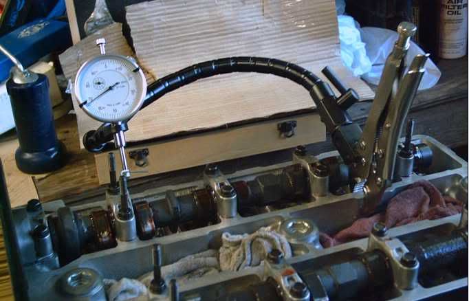
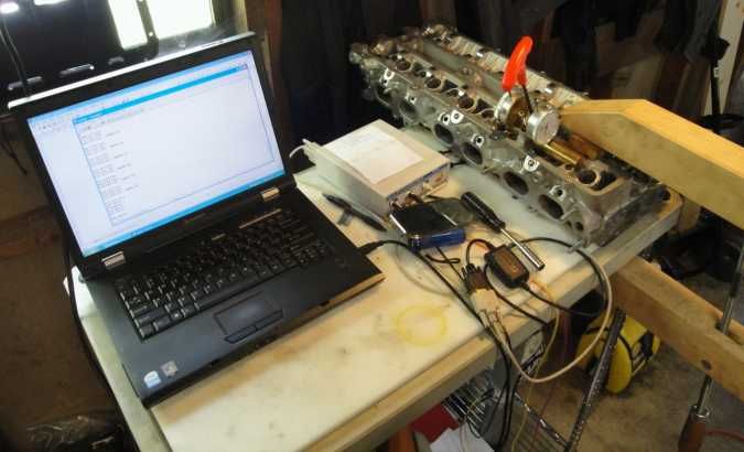
A discussion on porting generally leads to a discussion on testing the porting - the before, and after effects. A great tool for testing port work is a flowbench.

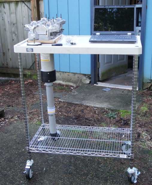
I used a kit found on the net for my bench (I do NOT recommend the model I have because the interface is NOT user friendly... and the manual was NOT written in a logical, methodical fashion) I then built my bench so it could be portable (if you've seen my work space you'd understand)

I can now do flowbench testing on... 82mm bore, 84mm bore, and now.......
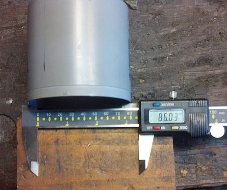
86mm bores

The 82mm adapter I got initially for testing Toyota 4AG/AF heads, and Honda B series heads...

the 84mm adapter was made for testing Toyota's 7MG head...

The 86mm adapter allows for testing MANY new engines - Subaru/Toyota FA20/4-UGSE, Mazda/Ford F2T, Toyota 1J/2J, Nissan SR20, Nissan RB25/26, Toyota 3SG... to name just a few...

A flowbench is just a tool... a special tool, I'll grant you, but like any other special tool (torque wrench, electrical meter, English Wheel) it requires a knowledgeable user, to get the most from the tools use.

Mr_Clutch42
Mr_Clutch42 Reader
5/31/14 5:33 p.m.

What's the name of the tool(s) that port cylinder heads? I don't remember what they're called.

oldeskewltoy
oldeskewltoy SuperDork
6/1/14 1:10 p.m.
Mr_Clutch42 wrote: What's the name of the tool(s) that port cylinder heads? I don't remember what they're called.

?? typically some rotary tool... depending on the size of the job it can be anywhere from 1/4" down to 3/32" Rpm levels I use range from 6,000 to 40,000

As far as what bits... I use carbide cutters, sanding drums of different diameters and grit levels. There is also a fair bit of hand work I do... some of those inside (blind) radii need finger tips for "eyes", as well as tools

oldeskewltoy
oldeskewltoy SuperDork
7/10/14 5:35 p.m.

Oh joy.... a Redline manifold... far right

The cams there are Tomei Poncams, their powerband is 3500 - 8000 ish. peak torque 5500-6000

length of intake port - mounting surface to back edge of intake valve = 4.1" (104mm)

thickness of T3 adapter = .9" (23mm)

The Redline DCOE manifold = 2.1"(53mm) Do to spacing... cyl 1 and 4 have a heavy taper and so valve #2 and #7 actually measure 2.35" (59mm).

The length of a DCOE (without velocity stack) = 4.64" (118mm)

Here's a little teaser... Do I want to use, or remove the .9" adapter plate? Why??

oldeskewltoy
oldeskewltoy SuperDork
7/15/14 10:07 a.m.
oldeskewltoy wrote: length of intake port - mounting surface to back edge of intake valve = 4.1" (104mm) thickness of T3 adapter = .9" (23mm) The Redline DCOE manifold = 2.1"(53mm) Do to spacing... cyl 1 and 4 have a heavy taper and so valve #2 and #7 actually measure 2.35" (59mm). The length of a DCOE (without velocity stack) = 4.64" (118mm) Here's a little teaser... Do I want to use, or remove the .9" adapter plate? Why??

Hmmmm... really... no takers???

http://s-86.com/article_intake.php

http://www.chrysler300club.com/uniq/allaboutrams/ramtheory.htm

http://www.team-integra.net/forum/blogs/michaeldelaney/130-intake-manifold-tech-runner-size-calculations.html

So... now with more information.... which is better.... keep the T3 delete plate (.9" thick), or discard it???

fidelity101
fidelity101 Dork
7/15/14 10:08 a.m.

In reply to Mr_Clutch42:

Burrs.

oldeskewltoy
oldeskewltoy SuperDork
7/17/14 7:42 p.m.

As can be seen below, the entire intake needs to be manipulated/adjusted, and then blended as one

black arrows - show direction of incoming air solid blue lines - show areas to be ported dashed blue line represents - the amount the manifold needs to be moved up.

So it is vital to determine the actual location of the manifold... in relation to the T3 delete plate, and then once they are mounted as one, to determine the T3 plate on the head.

So using 2 long bolts I fasten the manifold to the T3 plate set them as carefully as I can ( aligning the bottom port edges to be as flush as possible through all 4 ports) and them tightening the bolts to lock the 2 together.

Then I pick 2 points in the flange, one between cyl 1 and 2, the other between 3 and 4, that I can drill 2 small (3/32") holes... through the manifold and into the T3 plate. Then, using 3/32" x 1" roll(tension) pins I mount the manifold to the T3 plate in one place.

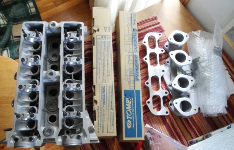
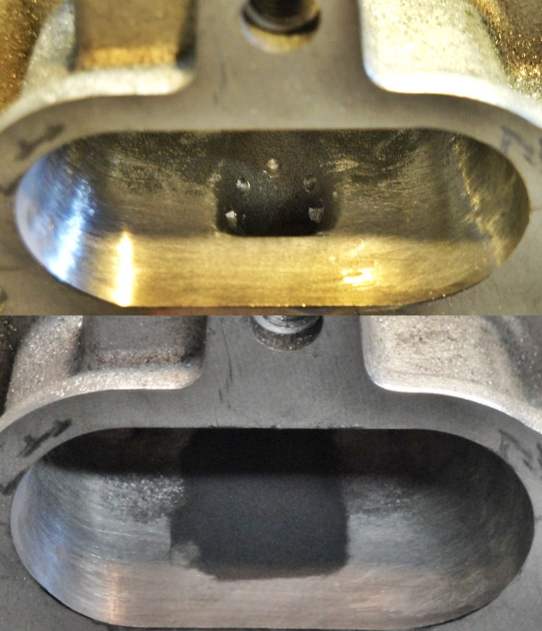
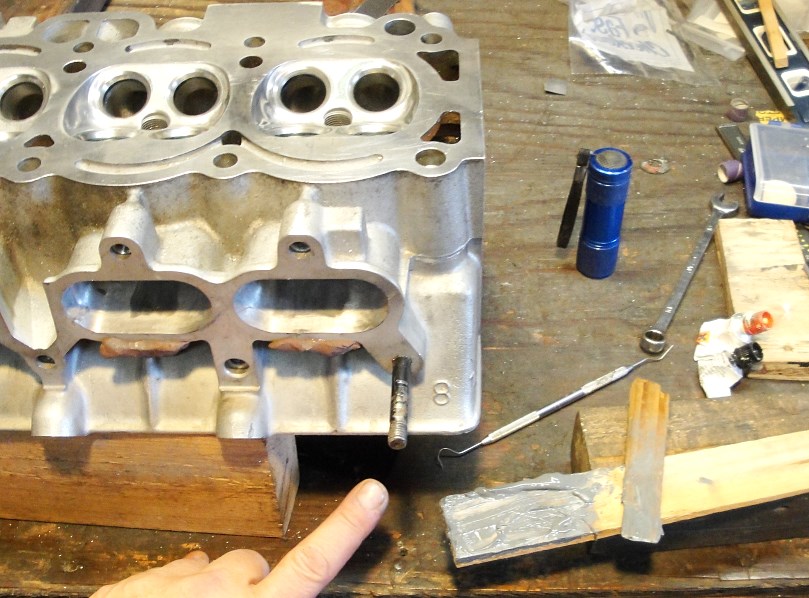
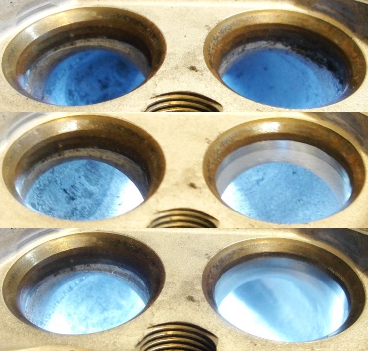
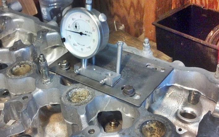
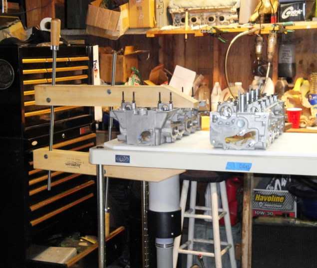
{note far left port in manifold(bottom in photo) has been ported to size, while the other 3 ports await...}

This, the roll pin mounts, will allow me to repeatedly mount and dismount the manifold from the T3 plate and then reaffix them in the same place, time after time.

As is typical with the T3 plate it is the overall size of the gasket... NOT the port...

so when laid over the intake... you can see the bottom edge, and the top edge of the head are in the airstream. The T3 plate is well situated horizontally. So as with the other T3 products I've worked, jack screws are added, and I'll be elongating the T3 mount holes to allow me vertical adjustment with the jack screws.

oldeskewltoy
oldeskewltoy SuperDork
7/23/14 1:04 p.m.
turboswede wrote: I had to do similar work to the DCOE manifold for my 924. It was a PITA to elongate the holes to shift it sideways enough to get it close enough to try and port match it to the head.

I see your elongated holes and I raise you horrible holes... center and to the right...

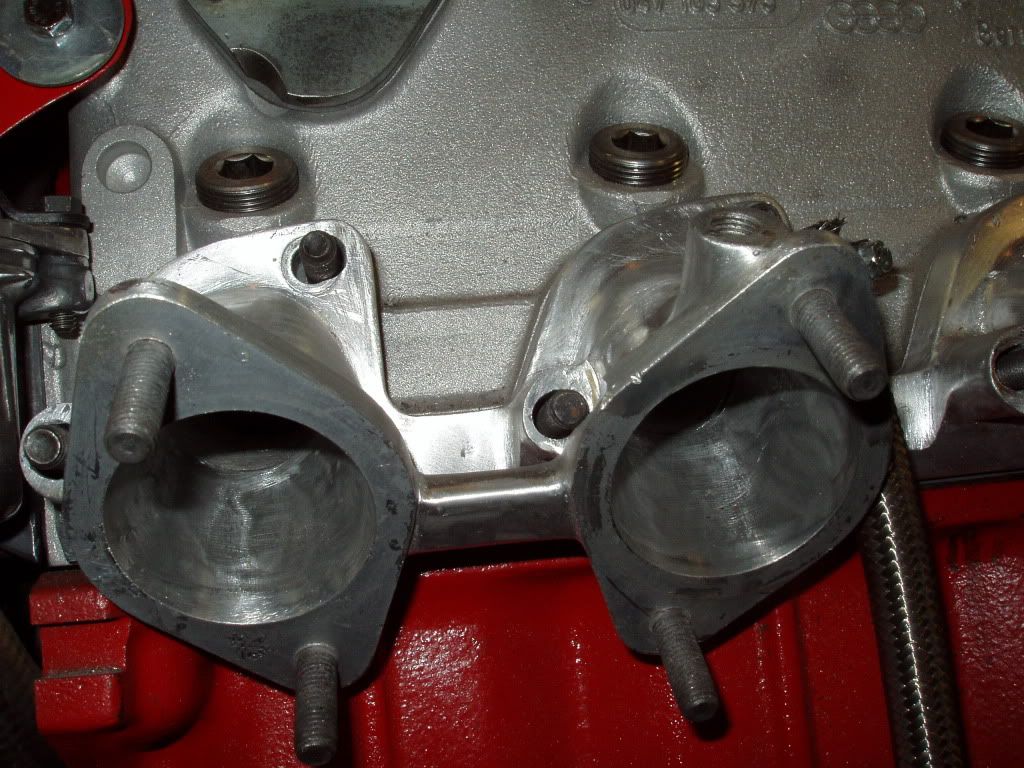
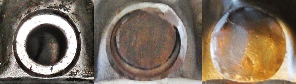
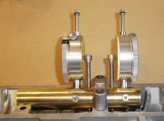
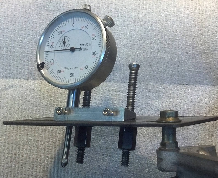
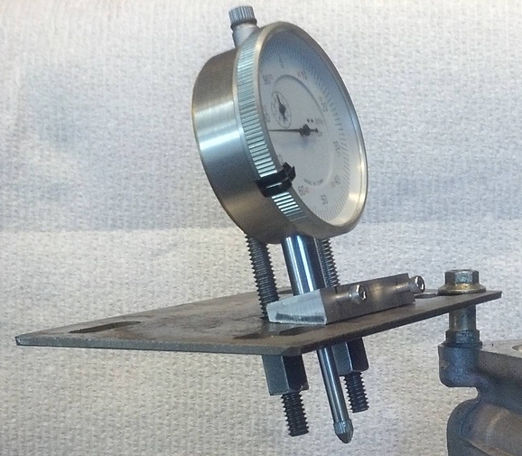
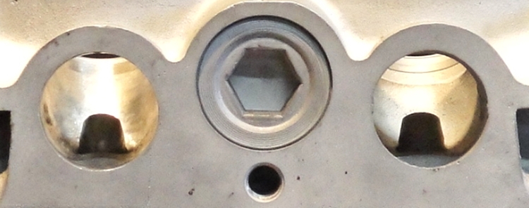
note the roll(or tension) pins used to hold it all together

The worst of which....

wearymicrobe
wearymicrobe SuperDork
7/23/14 1:55 p.m.
Mr_Clutch42 wrote: What's the name of the tool(s) that port cylinder heads? I don't remember what they're called.

I call it a Hass ES-5T and a credit card. Some of you guys are nuts, well almost all of you guys are.

Though I am totally stealing that casting idea to check flow on things I have trouble getting a bore scope into and to check castings in the future.

oldeskewltoy
oldeskewltoy SuperDork
7/23/14 5:56 p.m.
wearymicrobe wrote: Though I am totally stealing that casting idea to check flow on things I have trouble getting a bore scope into and to check castings in the future.

you'll need a small scale to measure grams... clear 16oz plastic cups... ProSil 1000 2 part silicone. also recommend small rubber scrapper/spatula... AND a cork screw...

.

.

.

.

back to the current job.... exhaust port 2 in transition

oldeskewltoy
oldeskewltoy SuperDork
8/7/14 6:22 p.m.

Combustion chamber in transition

oldeskewltoy
oldeskewltoy SuperDork
8/13/14 2:53 p.m.

Since this engine is going to be running carbs... the injector ports are going to be huge vacuum leaks unless filled....

Using the Dremel, and the 3/32" mandrel that comes with the Dremel, I drill 5 - 3/32" holes about 2-3mm deep spaced around the injector port. These, along with the top of the injector port, will be the anchor points for the JB Weld...

Yep JB Weld.... I've done some research into this. I've looked at some of the other products - Devcon for instance, and none of them offer the temp, and holding capability of the JB Weld - JB Weld FAQs

Its just been finished(filling).... note the change in the clay... it is a vital tool in this operation for it allows "adjusting" the volume of JB Weld - by either pulling the clay, or pressing the clay, i can change the level at the port roof.

Also I learned from injector port #1(center in photo above), that it is a bit better to begin filling the port with the clay slightly free to allow the JB Weld to completely fill the injector side of the port. There is enough JB Weld on #1, but #2(far right) is a more complete fill.

OST said: it is a vital tool

and here are a few others....

I use builders shims in a LOT of my work... they are great for setting the head up for checking chamber volumes, and here I'm using them as applicator/spatula, and as my palate for mixing, and applying. The dental tool helps remove the clay, or as much as I can... the spent tubes of JB Weld... and my finger! A wet finger allows me to shape and fill the voids... I prefer to use water... but saliva works in a pinch

oldeskewltoy
oldeskewltoy SuperDork
9/14/14 2:56 p.m.

Nissan SR20DE head... exhaust short radius...

left bowl/seat is the control, as the right bowl/seat transitions from raw to nearly finished.. creating a short radius from nothing

Knurled
Knurled GRM+ Memberand PowerDork
9/14/14 3:17 p.m.

I will leave this here...

http://www.clubgti.com/showthread.php?146976-Modified-8v-project-head

wspohn
wspohn HalfDork
9/16/14 11:27 a.m.

Amen on the flow bench.

I've seen too many heads done by morons with high speed grinders operating with no real data but the vague thought that 'bigger must be better'. They usually ended up with inferior flow to even the stock heads.

captdownshift
captdownshift GRM+ Memberand HalfDork
9/16/14 1:42 p.m.

this thread would have me tempted to pick up a certain 4AGE powered RWD rally car (that's in need of updating) if SWMBO weren't so dead set on getting a Miata.

great work.

oldeskewltoy
oldeskewltoy SuperDork
9/16/14 6:55 p.m.
wspohn wrote: Amen on the flow bench. I've seen too many heads done by morons with high speed grinders operating with no real data but the vague thought that 'bigger must be better'. They usually ended up with inferior flow to even the stock heads.

The "Loynings test" is a head I ported and then paid Loynings to test, this was before I began offering my services.

and as far as the ability to match work from one port to the next... less than a 1% difference

alfadriver
alfadriver UltimaDork
9/16/14 7:08 p.m.

One note on the flow bench- for the exhaust side, you should push instead of pull. The aero physics are totally different.

A buddy of mine has done a ton of development on an Alfa head, and having a pushing bench really showed some problems in the stock port. Not sure if this engine will show the same...

Another interesting illustrator was a small tuft of string on a small stick. Using that, he found a massive flow separation at the bottom of the exhaust port. A sucker bench would never see that.

oldeskewltoy
oldeskewltoy SuperDork
9/16/14 10:31 p.m.

In reply to alfadriver:

wouldn't do it any other way....... just reverse the flow(swap the shop vac from suck to blow), and swap 2 air feed lines...

alfadriver
alfadriver UltimaDork
9/17/14 7:31 a.m.

In reply to oldeskewltoy:

Just wanted to make sure. It's not obvious...

BTW, did you try the string on a stick thing to check for flow separation? Seemed to help my friend a LOT figuring out what is wrong with the Alfa head.

oldeskewltoy
oldeskewltoy SuperDork
9/17/14 10:57 a.m.
alfadriver wrote: In reply to oldeskewltoy: Just wanted to make sure. It's not obvious... BTW, did you try the string on a stick thing to check for flow separation? Seemed to help my friend a LOT figuring out what is wrong with the Alfa head.

The Flow Performance kit (see 1st post top of this page) I purchased has a velocity probe... so I can find and measure those zones.

What I find a bit more interesting.... is valve setting, and how the porter goes about RELIABLY measuring (his accuracy on set up), with mounting on the bench, setting equipment, then measuring the port, then removing to port, then resetting everthing...

At least for the Toyota 7M and 4A heads, I have an UBBER reliable tool that allows me no question of its accuracy.....

prior to this I used this.....

FAR less reliable/accurate!!!

oldeskewltoy
oldeskewltoy SuperDork
10/14/14 7:06 p.m.
oldeskewltoy wrote:
alfadriver wrote: In reply to oldeskewltoy: Just wanted to make sure. It's not obvious... BTW, did you try the string on a stick thing to check for flow separation? Seemed to help my friend a LOT figuring out what is wrong with the Alfa head.
The Flow Performance kit (see 1st post top of this page) I purchased has a velocity probe... so I can find and measure those zones. What I find a bit more interesting.... is valve setting, and how the porter goes about RELIABLY measuring (his accuracy on set up), with mounting on the bench, setting equipment, then measuring the port, then removing to port, then resetting everthing... At least for the Toyota 7M and 4A heads, I have an UBBER reliable tool that allows me no question of its accuracy..... prior to this I used this..... FAR less reliable/accurate!!!

Since I'm dabbling in a Nissan SR20 head[s], I made a valve setting tool for it as well...

and fitted to an SR20 head....

oldeskewltoy
oldeskewltoy SuperDork
10/31/14 7:09 p.m.

Dabbling off to the side (spending my own time on the SR20 head....)

a few views of a Toyota 5MGE (82-85) Supra head..... intakes....

exhaust...

oldeskewltoy
oldeskewltoy SuperDork
11/18/14 12:03 p.m.

Trunks aside......

a bit on the intake side

and a bit of exhaust work....

and that exhausts(one on the left) transitioned....

oldeskewltoy
oldeskewltoy SuperDork
11/20/14 1:57 p.m.

1 2 3 4 ... 13

You'll need to log in to post.

Our Preferred Partners
uaawXMEGPo3WWezOBMZR25adwtscCATcel0UrbzxDnEjpyeYTba7mlx0E8ttxZ8e