1 ... 21 22 23 24
Shavarsh
Shavarsh HalfDork
2/25/24 3:45 p.m.

In reply to TurnerX19 :

Turner, I'm not sure I understand. Are you referring to radio frequency? Or some induced current?


Edit:

Both the ECU manufacturer, and my electrical hardware expert buddy agree that the likely cause of failure was plugging in the second relay while the car/ecu where on and running. I've gotten lax about disconnecting power before making changes, probably due to working with older junk that doesn't care for awhile.

The outputs on the chip are paired, so they should be good for 1 amp each. I put my multimeter in line with each relay, and they all tested at ~129mA through the ground side of the coil. Even with 2 relays, 260mA doesn't approach the 1A capacity of the chip. I'll replace the chip, wont plug things in while running, and keep my fingers crossed...

Shavarsh
Shavarsh HalfDork
2/27/24 2:03 p.m.

While waiting for the chip to come in, I decided to test out some non-roller rockers. This engine has always made a loud ticking sound, and my dissection of the lifters did not make a difference. It seems that every sbf with roller rockers has some amount of ticking sound. I'd like to try some stock style rockers to see if the noise disappears. So I ordered a set of Elgin RK610 ( listed application: 289 CID (4.7L) 1965-1968 From 10/4/65, 302 CID (5.0L) 1968-1978 Except Mustang Boss, 351 CID (5.7L) 1969-1978 Windsor). Here are some pictures:


The parts seem to be very good quality, but I'll clearly need new pushrods to make these work. Even with new pushrods, I'm not sure if the spring retainers will clear. Comp sells a set of rockers (1231-16) that should work, but are more $$ and will likely also need pushrods. Without an adjustable pushrod, I can't check if the slots are long enough for the .512 intake lift. I'm leaning toward returning these, and not spending more money on this right now, but I'll give it some thought for a few days.

Shavarsh
Shavarsh HalfDork
2/28/24 2:18 p.m.

The chips came in, and we had a bit of fun at the soldering station. My throat is sore today... don't breathe lead fumes kids. First, to remove the old chip I used a new method I saw on youtube. The idea is to solder all the pins on each side together, then use 2 soldering irons to melt all the solder simultaneously, and lift the chip off. For the most part it worked great. Hopefully I won't be getting enough practice to get good at it.


Next stick the new chip on an solder all the pins. This wasn't very hard to do, but my results are far less aesthetic than the original job.


A quick test in the car has the fans coming on, and the fuel pump properly priming. I'll need to hook everything back up and correct the troubleshooting efforts in the tune before going on a drive and calling the effort a success.


Nukem
Nukem GRM+ Memberand Reader
2/28/24 2:38 p.m.

That will clean right up with some isopropyl alcohol.

or it would if you hadn't already stuffed it back in the car.
 

This bodes well

Shavarsh
Shavarsh HalfDork
2/29/24 1:27 p.m.

In reply to Nukem :

Yeah, I cleaned it up as much as I could before reassembling.


Short test drive was successful. It showed the chip was functioning, and showed how badly I need to do some idle tuning.

Shavarsh
Shavarsh HalfDork
3/1/24 12:02 a.m.

Well... that didn't last long. 

Tonight I set out for a big parking lot to do some idle tuning. Shortly into the drive, I lost the tachometer. I didn't think anything of it and kept driving. When I got to the lot I put the car in accessory mode to let the fans run. The fans didn't turn on. Also the fuel pump now continuously runs as before.... one of the fan fuses was blown (it was still a low amp fuse from testing) but the other fuse didn't blow. Tunerstudio is showing the fans on, and the relay isn't clicking... The chip doesn't look burned up like it did before, but these are the same symptoms.

Piguin
Piguin Reader
3/1/24 1:52 a.m.

That sucks.

Any chance that the cause might not be the chip but some plug somewhere shorting out?

Although I would check the tabs on the chip for cracks.

Nukem
Nukem GRM+ Memberand Reader
3/1/24 9:05 a.m.

Is the ECU controlling just those two relays (fuel pump and fan)? Sounds like that same UL2803A might be getting used for all the 12v outputs (tach signal, etc.) as well.

Shavarsh
Shavarsh HalfDork
3/1/24 3:40 p.m.

In reply to Nukem :

Yes, I believe you are correct. That chip controls 4x12v outputs (at least). I've ordered some inline fuse holders to add to each output. I'll put .5A fuses in them, and see who is drawing too much. Any other suggestions? I'm not sure if all of this could be solved with the addition of some diodes. 

Shavarsh
Shavarsh HalfDork
3/7/24 1:40 p.m.

Chip #3 went on much mor nicely, I'm getting better at this.


After reassembling with a .5A fuse in line with each of the 4 outputs from the chip, we were up and running again. First, the tach doesn't work. I assume this is from the addition of the tiny fuse. Second, I was still having a hard time with the fan output. So I reassigned the fuel pump output to the fans, and the fuel pump is now running on the spare low current output. Alright! time to get into the idle tuning... until the used IAC gave up.

After a bit of sleuthing, i found a broken diaphragm. The valve was also not seating when unplugged, or at 0% duty cycle. So, new parts inbound. Let's upgrade to the aluminum flange version right?


Well, not quite. This part does not work for this application. It seems that it would work correctly if I mounted it backwards (but there is interference with the valve cover). The shiny block off cap is not sealed, and neither is the solenoid body, leading to a vacuum leak that cannot be controlled. So, a replacement 94 Mustang IAC is on its way.

DRProjectCentral
DRProjectCentral New Reader
3/7/24 2:38 p.m.

I finally managed to read the history on this thing. What a project! Feel free to get into the weeds on all the electrical best practive stuff too, I'll be shortening the wiring harnesses on the Fiat and I have zero experience in that area. Also, ABS trigger conversions. 

This thing is SICK

Shavarsh
Shavarsh HalfDork
3/8/24 12:39 p.m.

In reply to DRProjectCentral :

Thanks DRP! I'm enjoying keeping up with your project as well.

Also, I am very pleased that after replacing the IAC with the correct part, idle speed is predictable and easy to control. I may not even need to run closed loop, we will see.

Shavarsh
Shavarsh HalfDork
3/12/24 6:49 p.m.

Throughout the issues with the LC output chip, the engine has been getting hotter than normal. Including in cooler weather. Suspecting an air bubble, I filled the coolant overflow a few times (this car has always been good at self burping). However, after getting it good and hot, I could see and hear air escaping from the water neck. Lets pull it off and reseal. While it's off, lets check flatness...

Huh, turns out it was very far from flat. After some work with the grinder and time with the sand paper:

Much better. Also, no more overheating. Now that I have been driving for awhile without blowing the chip, it's time to start adding things back in. First, I put the fuel pump back on the default fuel pump pin, and moved the fan control to the spare LC output. For now, I'll leave the .5A fuses inline, however I decided to trigger the second fan relay with the first fan relay rather than triggering both with the ecu output.

Once I have some drive time on that change, I'll take the fuse out of the tachometer signal wire. Hopefully that restores function to the tach, and doesn't blow the chip.

Shavarsh
Shavarsh HalfDork
3/18/24 2:30 p.m.

Putting some more miles on the car.

Piguin
Piguin Reader
3/25/24 5:59 p.m.

Good to see it on the road!

Shavarsh
Shavarsh HalfDork
3/25/24 11:10 p.m.

Thanks Piguin! Much appreciated.

Shavarsh said:

"I'll take the fuse out of the tachometer signal wire. Hopefully that restores function to the tach, and doesn't blow the chip."

Well, for the last week or so I've been trying to restore function to the tach. This required doing a bit of learning. First, there was no function at the tach after removing the .5A fuse. Also no response moving the ecu jumper from 12V output to 5V output. After this I tried the last open low current output (with no pull up) and no luck. Next I learned to use an oscilloscope to check the signal. No signal on the default output, or on the spare low current output....

Then I learned about pull up circuits. Pretty genius actually. For those that don't know, here is a diagram:

The idea is to use a large enough resistor on the power source to reduce the current enough that the switched ground can easily "pull down" the Vout to ground when activated. When the switch is open, the current is enough to "pull up" the voltage to equal the power source. 


To tie it all together, the reason my spare low current output didn't work was that there was no power source in the circuit. The output is a switched ground, and the tachometer is expecting a square wave of 12V/0V. Without a power source the output is a 0V/0V square wave (no signal). Once I moved over to one of the high current outputs (small connector pin 12, Arduino pin 28), I used a 10k Ohm resistor and tapped into the hot side of the usb charging port for power. I also added a .5A fuse because I'd really like to be done soldering on this ECU for awhile.

Finally success. We have a functioning tachometer again.

Shavarsh
Shavarsh HalfDork
4/8/24 1:12 p.m.

So, while chasing a smooth idle, I have been trying all sorts of things. I can get the car to idle nicely, but it will disrupt itself (missfire) after a bit, and start to hunt. When settings are in a sweet spot, it will immediately recover, until it misses again. Recently I have been following andy whittles advice on youtube, and watching for consistent injector pulse width. After chasing "spikes" in the pulse width toward 0ms, I decided to flatten all of my maps, crank up the data sampling rate, disconnect the IAC, turn off all ego correction, all idle control, all acceleration enrichment, and everything else I could find. This resulted in the following images:

In the chart you are seeing commanded pulse widths under 2 ms. They always are focused around 900rpm, but not always the same #. I have not found a reference to 900rpm in any settings. In the line graph bellow you see the full data set. The green trace is PW, and is highly unstable. 


Here is another example with Red = PW, Green = RPM, and White = VE

:

You can see that even with a stable VE, and relatively stable rpm, the PW is unstable. Another interesting note, the PW is only unstable at idle, and usually around 900rpm. 


Next I took some tooth logs. The standard tooth logs did not show anything unusual on the crank trigger, but on the  composite logs we see less stable behavior:

This is not the best example, but you can see there are simultaneous high and low data points on the crank trigger at multiple points, and the cam signal is too close to one of the crank pulses. Elsewhere in the log there are gaps where there is no missing tooth, and multiple simultaneous data points. 


This seems significant. The disruptions are not enough to show up as sync loss. My thoughts are that the disorganized data from the crank wheel causes a momentary sync loss, where injector pulse width falls toward 0, causing a missfire. Or, there is a mechanical issue causing a random missfire that is causing disorganized crank trigger readings. raising the software filtering on the triggers does not seem to have an effect.


More investigation to come.

Edit: During this process I found why my VE values are so high. I finally started logging Gamma Enrichment, only to find it at 51% when warm.... After correcting the coolant temp based enrichment map to end at 100% instead of 51%, I divided the whole VE table by 2. Now the numbers are far more realistic. Unfortunately this did not effect the above issue.

Shavarsh
Shavarsh HalfDork
4/9/24 2:09 p.m.

Vindication!

After 2 weeks of in depth troubleshooting I learned:

There is a firmware bug in the version I am using that affects the VE table at..... 900rpm.

New firmware has been loaded, testing to follow.


I am getting what I paid for.


Speeduino is an evolving active project. I may make different decisions next time and choose a stable, commercial product. However, for now I am (hopefully) benefiting from the steep learning curve. The next time I set up a tune, I'll have a good depth of background knowledge.

Shavarsh
Shavarsh HalfDork
4/16/24 3:14 p.m.

The new firmware immediately fixed my idle issues, and made the clutch release area of the map much more stable. I've been tuning without any corrections this week, and the map is getting to a nice stable place. After the autocross this weekend I'll dive into closed loop idle and PID EGO control. Although this rabbit hole has involved far more learning and troubleshooting than I intended, performance is in fact more stable than with the carburetor. 

pres589 (djronnebaum)
pres589 (djronnebaum) UltimaDork
4/16/24 3:30 p.m.

Awesome work figuring things out with this engine management.  

wawazat
wawazat SuperDork
4/17/24 7:34 a.m.

I am really enjoying this thread and your build!   

Shavarsh
Shavarsh HalfDork
4/19/24 1:22 p.m.

Thanks for the encouragement pres589 and wawazat!

With 2 days until my first autocross of the year, and first with EFI, lets start a project. You may remember 2 months ago when my swaybar links disassembled themselves. Well, about a week ago they were able to do it again. Instead of using large capturing washers, I decided to fix it how Mazda fixed it.

First remove the link bracket from the arm:


Then cut the brackets off a spare set of nb front control arms and swap those on:

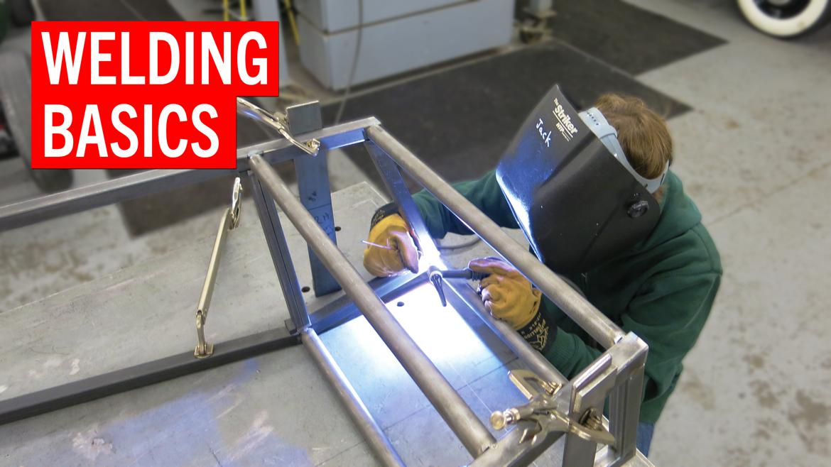
Weld it up splash it with paint, and duplicate on the other side:

I believe the brackets I grabbed from the front arms have a bit more rake to them than the rear brackets should, but I'll run them like this for now. If one of these links fails quickly I'll know I'm outside of their operating angle. In other news if anyone has a larger rear sway bar for an NA/NB they want to get rid of let me know.

Dusterbd13-michael
Dusterbd13-michael MegaDork
4/19/24 2:14 p.m.

If I remember correctly the front sway bar from a Dodge Neon is almost a direct Bulletin to the rear of amiata

Shavarsh
Shavarsh HalfDork
4/19/24 4:53 p.m.

In reply to Dusterbd13-michael :

Hmm that is very interesting. I'll see if I can find any references to that on the web.

Dusterbd13-michael
Dusterbd13-michael MegaDork
4/19/24 4:55 p.m.

In reply to Shavarsh :

I don't know if there will be or not. I had a neon and Miata sway bar next to one another at the time

1 ... 21 22 23 24

You'll need to log in to post.

Our Preferred Partners
yBVmELDwgVZKZP4r5XGZtRr42X1HDIHQZsKM6dLij6KeezXWeK03o1z5O6uzrJdi