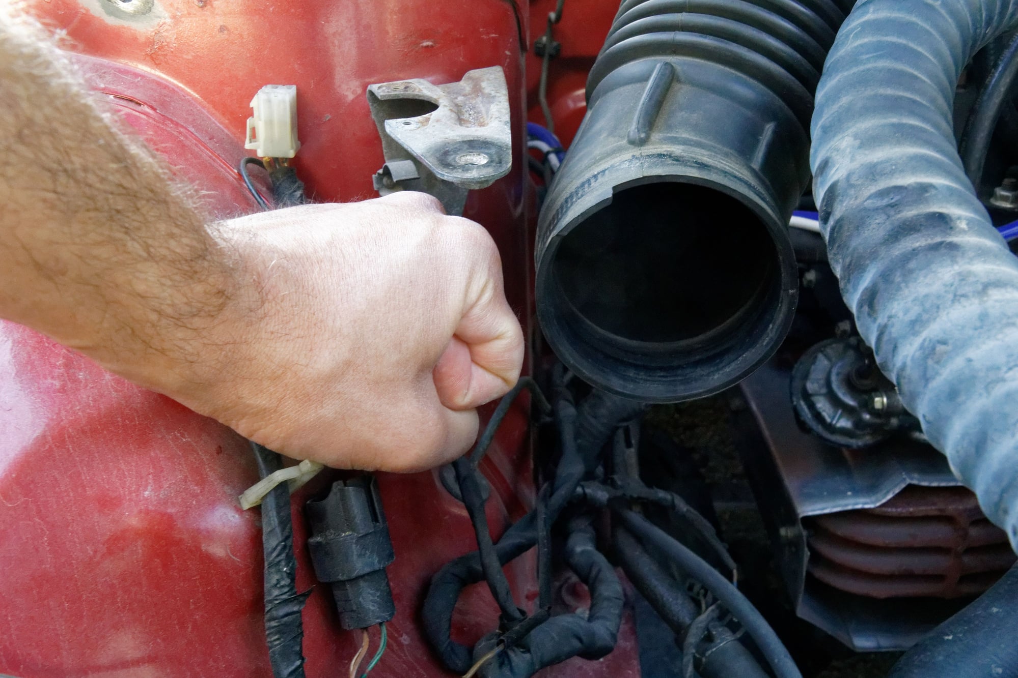
For our next installment of “parts everyone else throws away but I go to way too much effort to keep”, we need to talk about the air pump.
I left off talking about a solution for the air pump that didn’t involve the belt-drive or the ACV. Unfortunately, my research basically turned up no electric air pumps that were designed for constant duty.
The Rx8 for example only runs it’s pump during warmup. Most of the pumps I have looked up say something to the effect of “90 seconds maximum continuous run time”. They just aren’t designed to do what I want them to do and run all the time.
This left me with the stock pump. It’s reliable, it’s purely mechanical, and it has a built-in clutch so it freewheels past about 3000rpm and doesn’t rob too much power. Unfortunately there’s a glaring issue with that plan which I have yet to figure out, but we’ll come to that later on (bonus if you can figure out what it is).
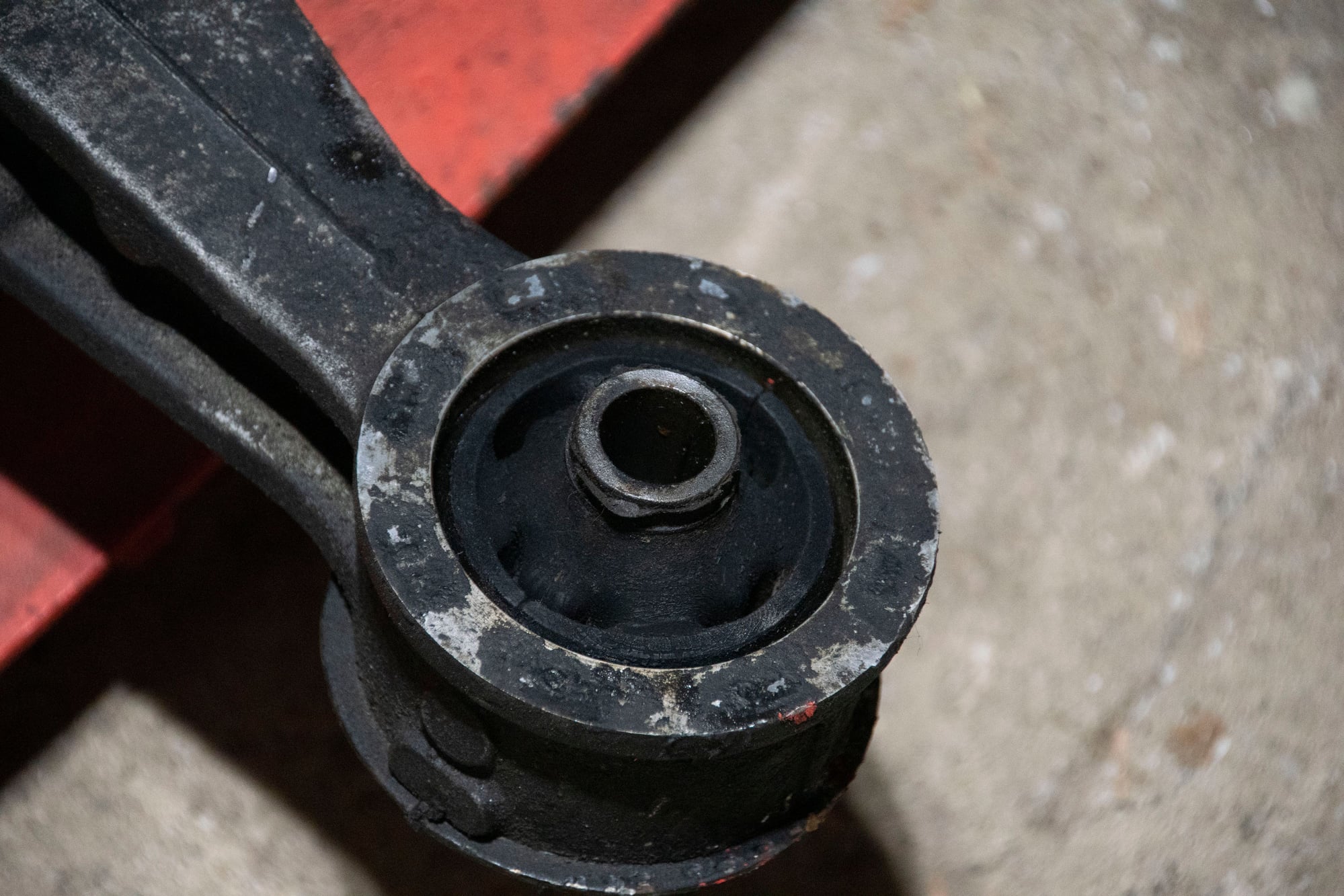
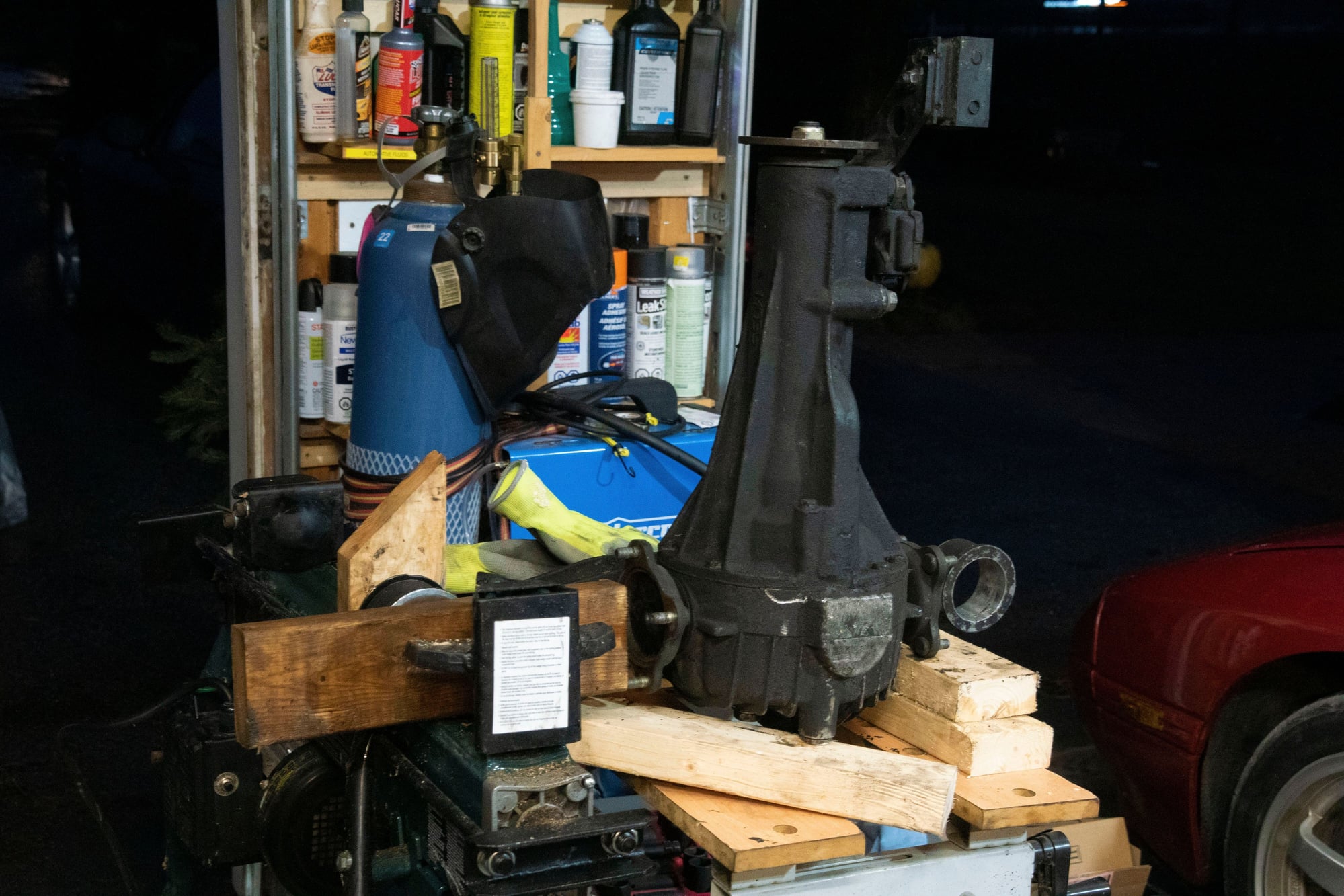
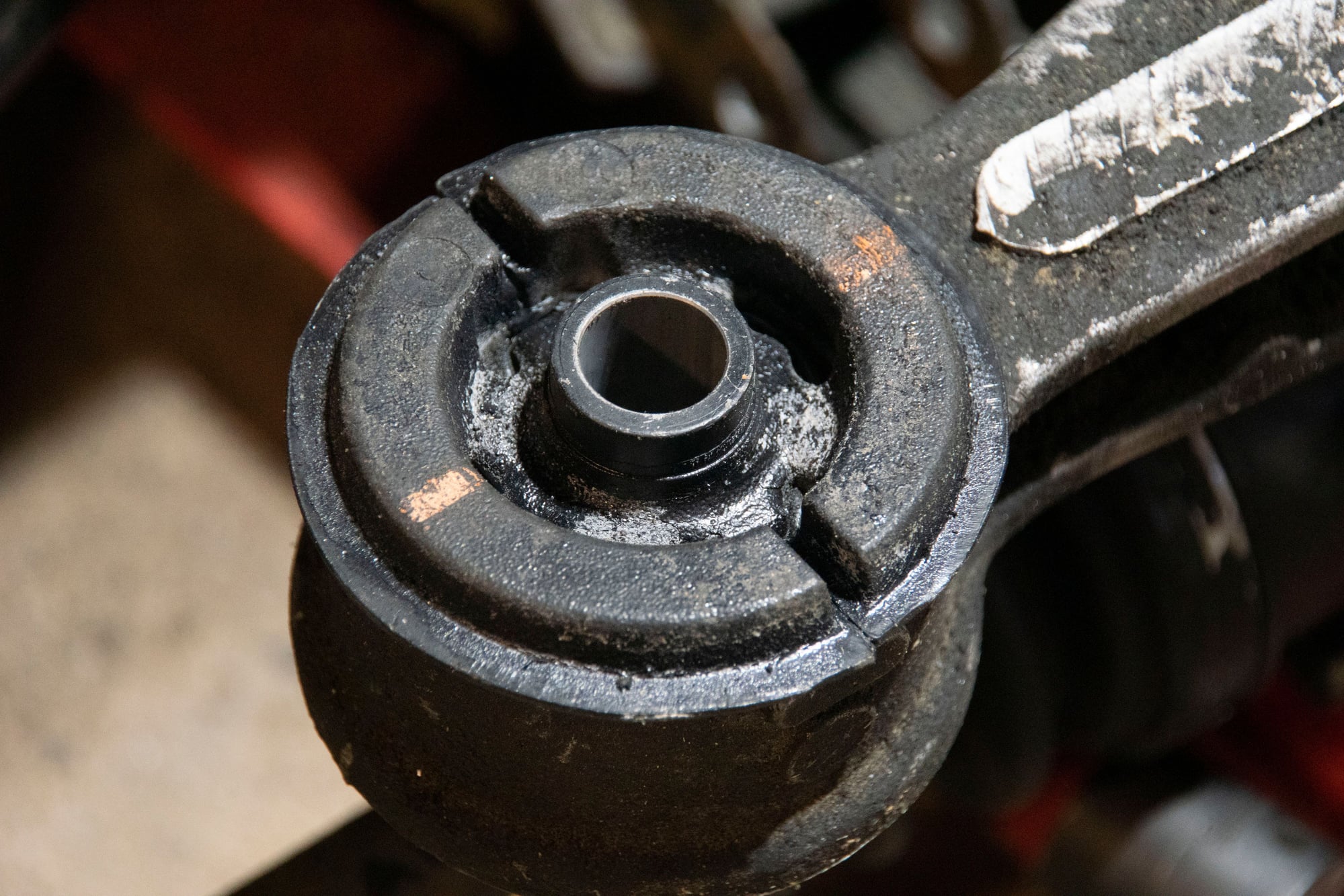
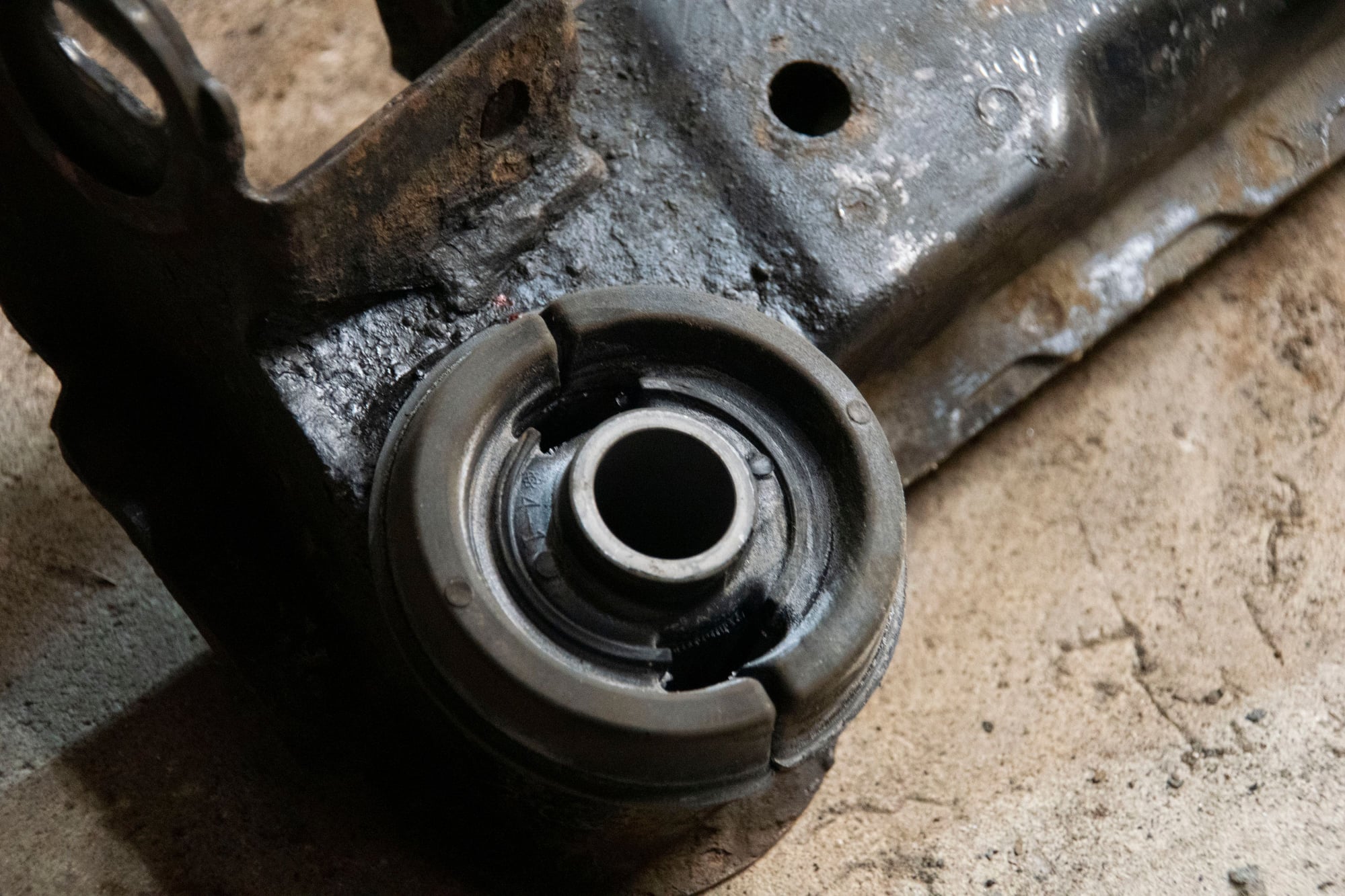
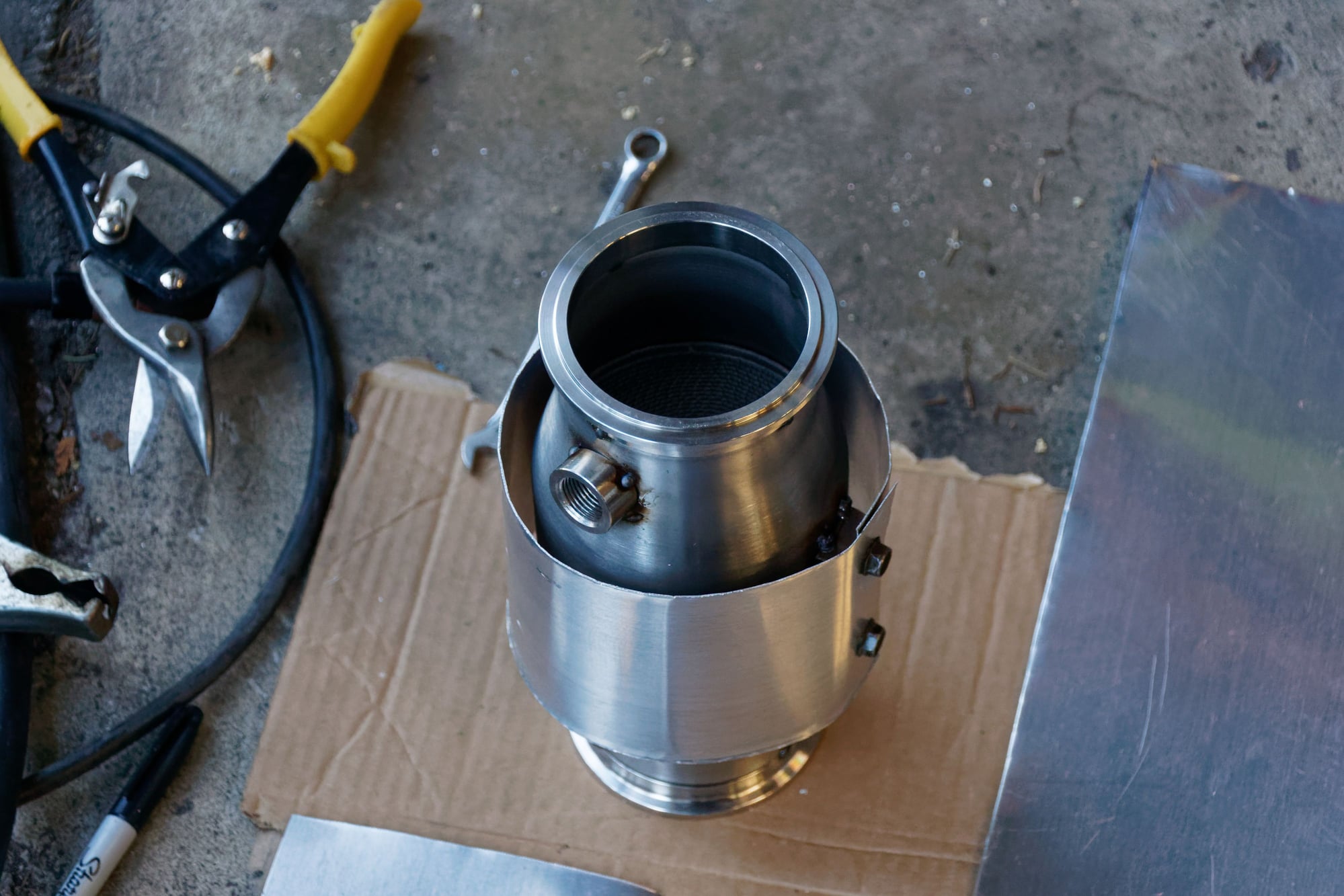
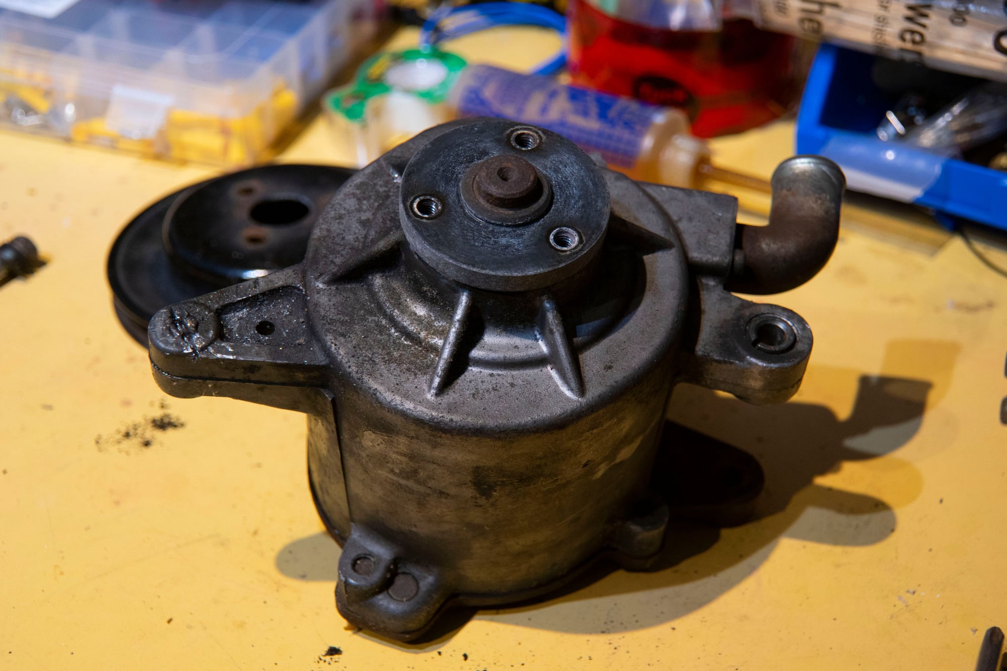
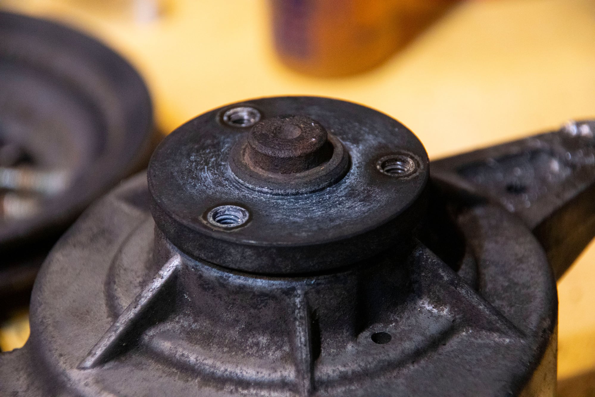
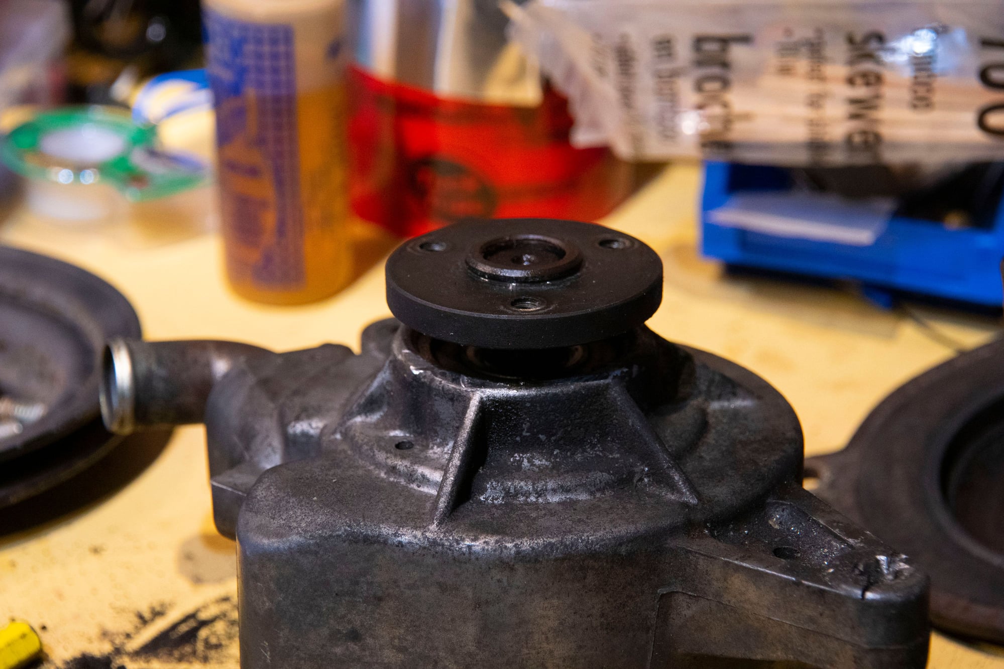
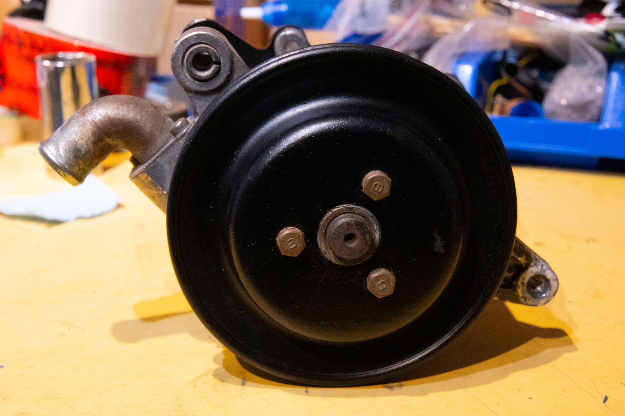
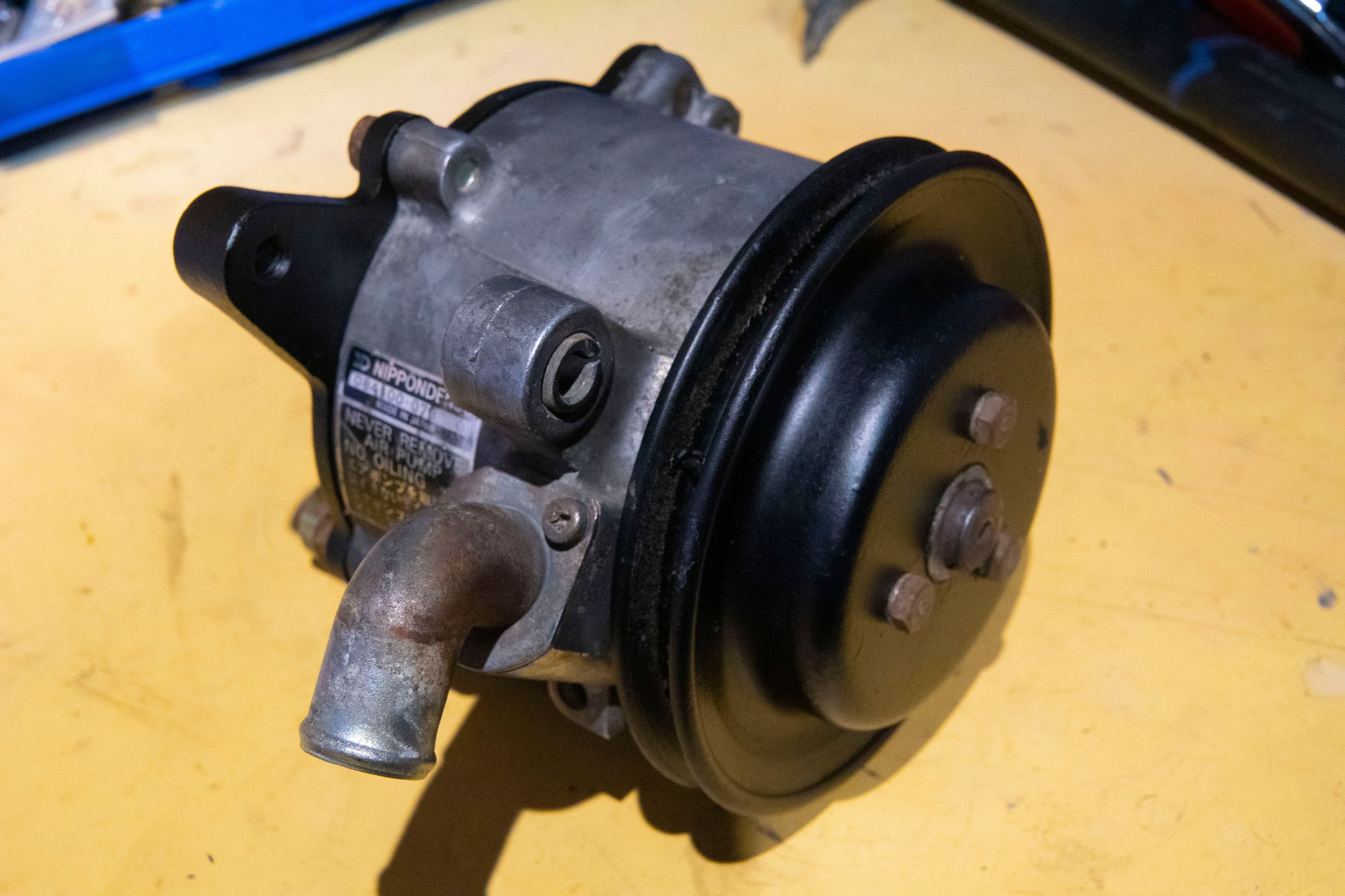
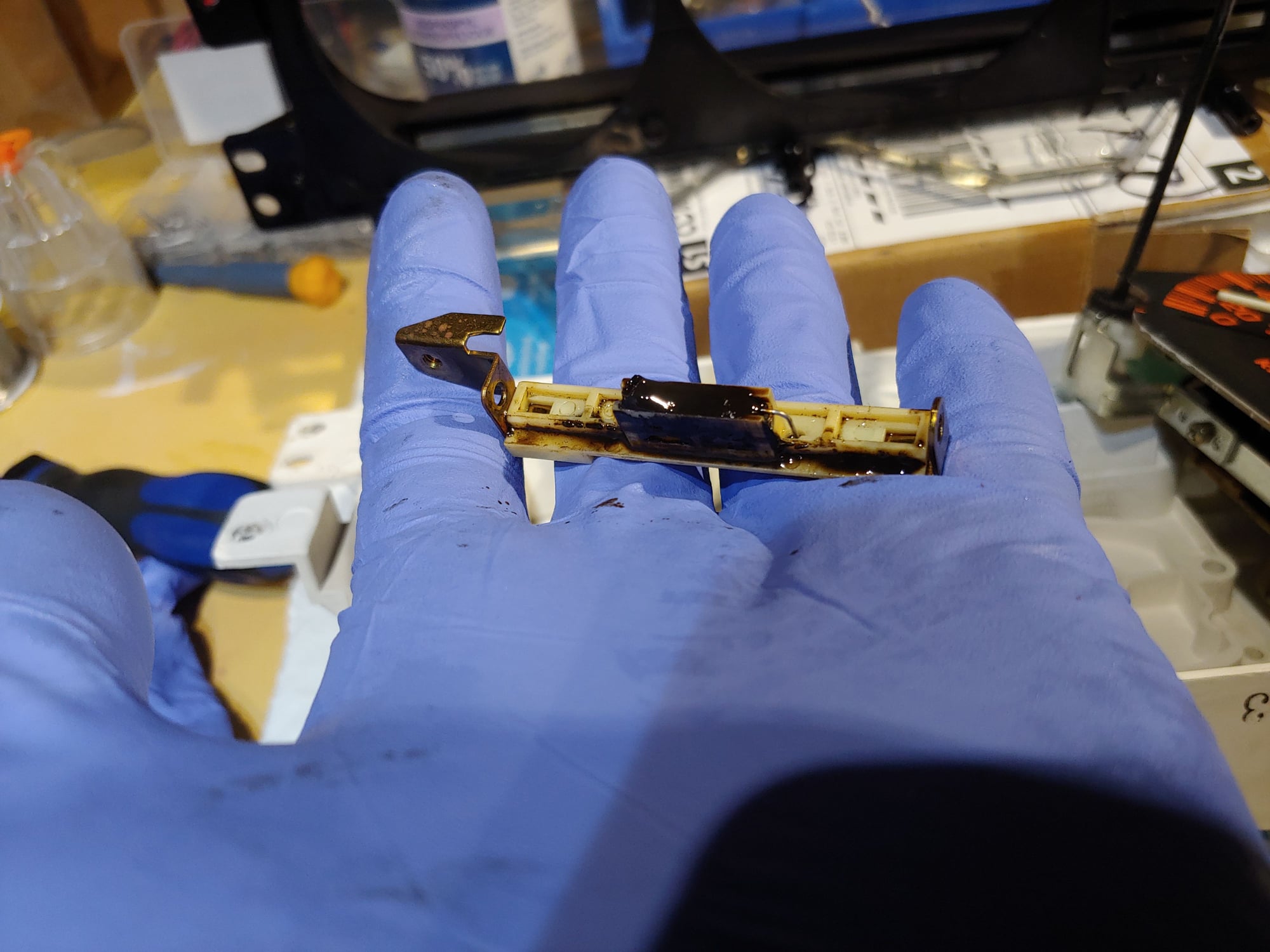
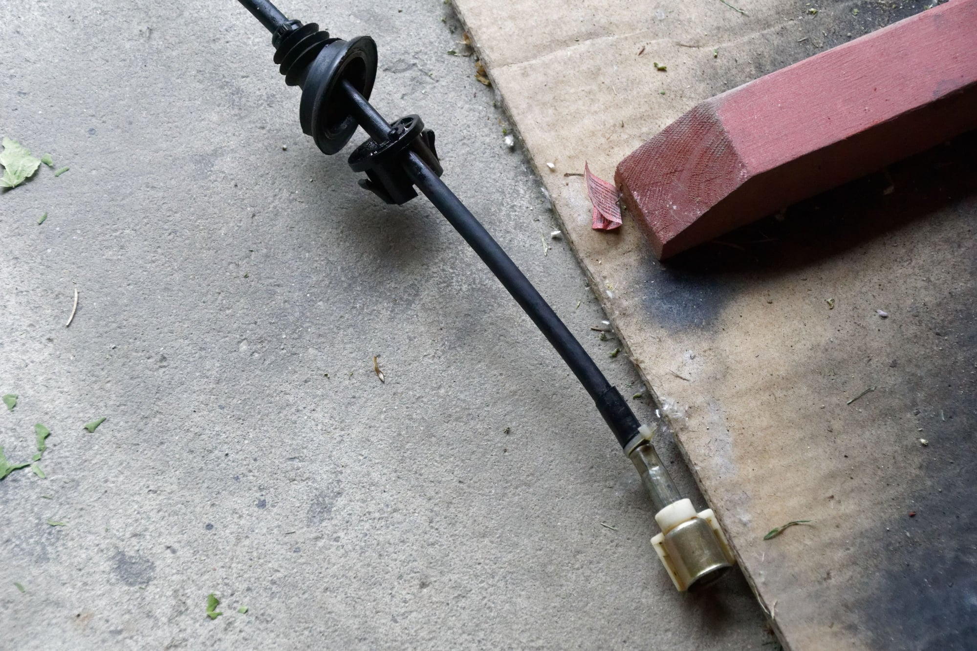
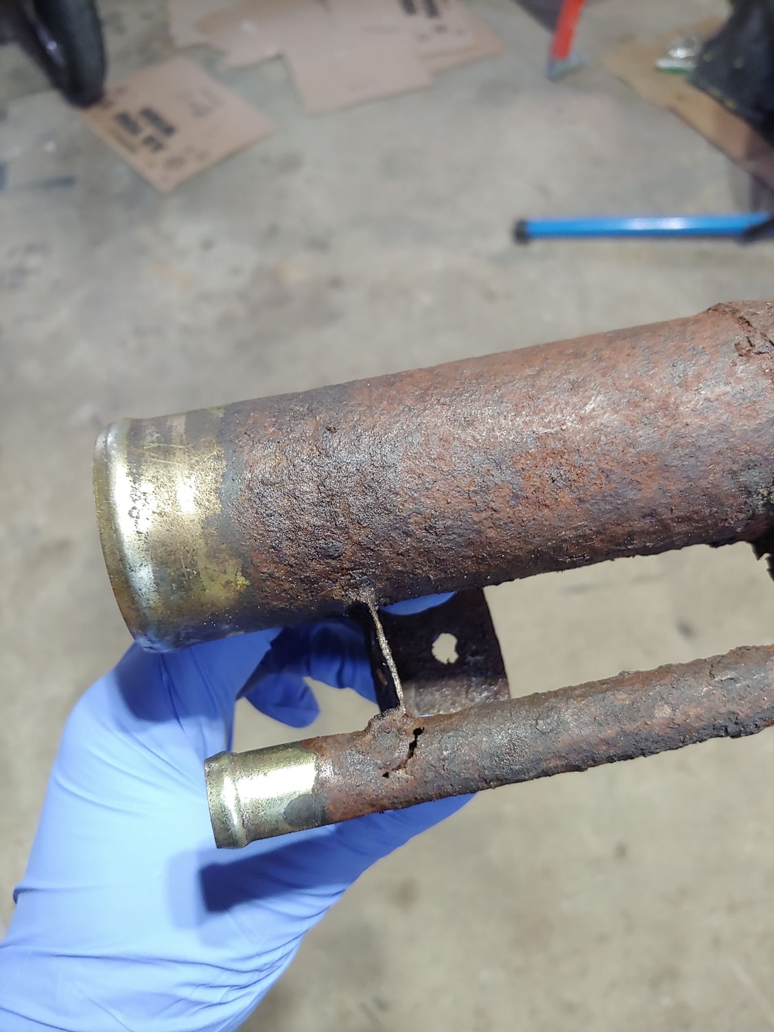
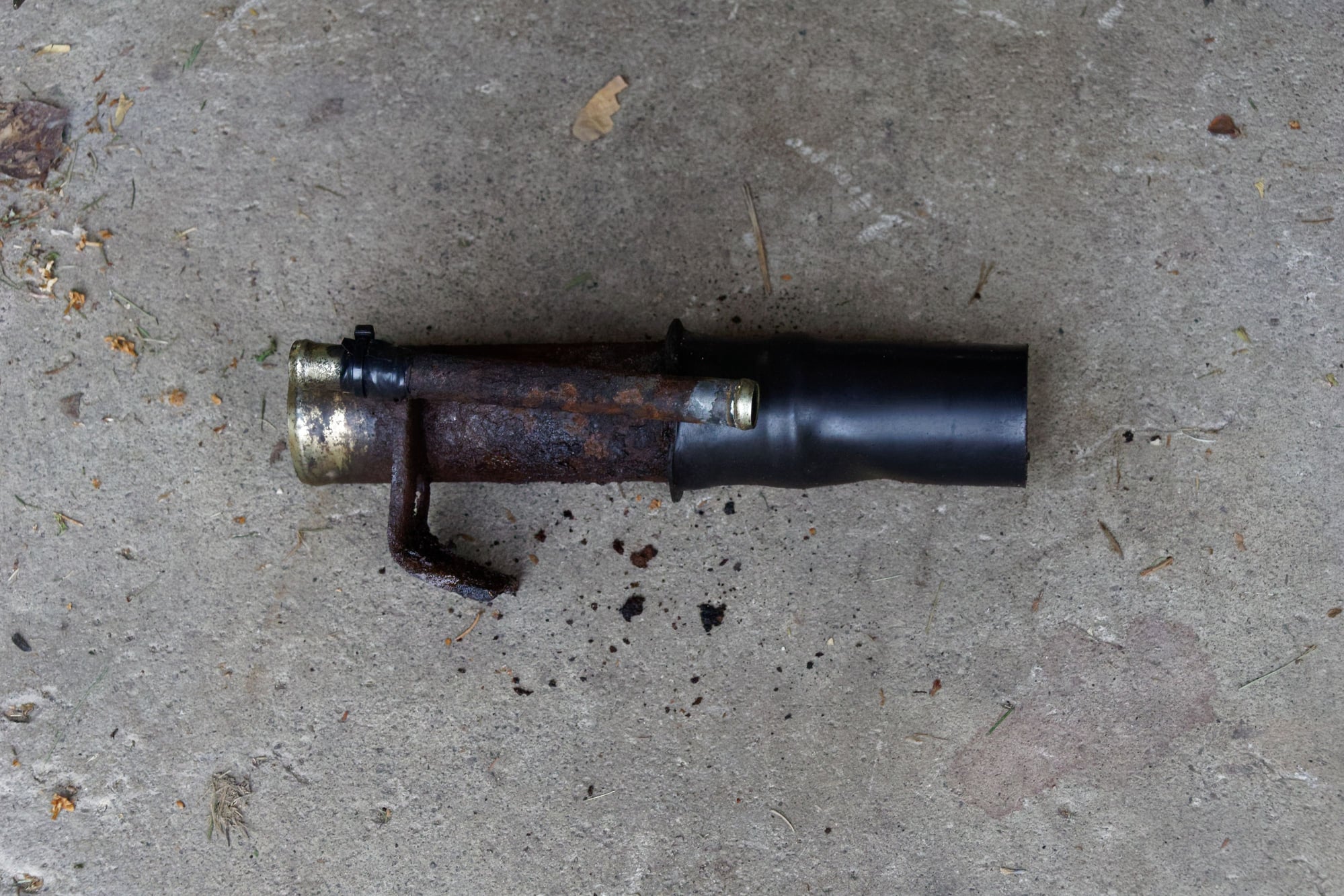
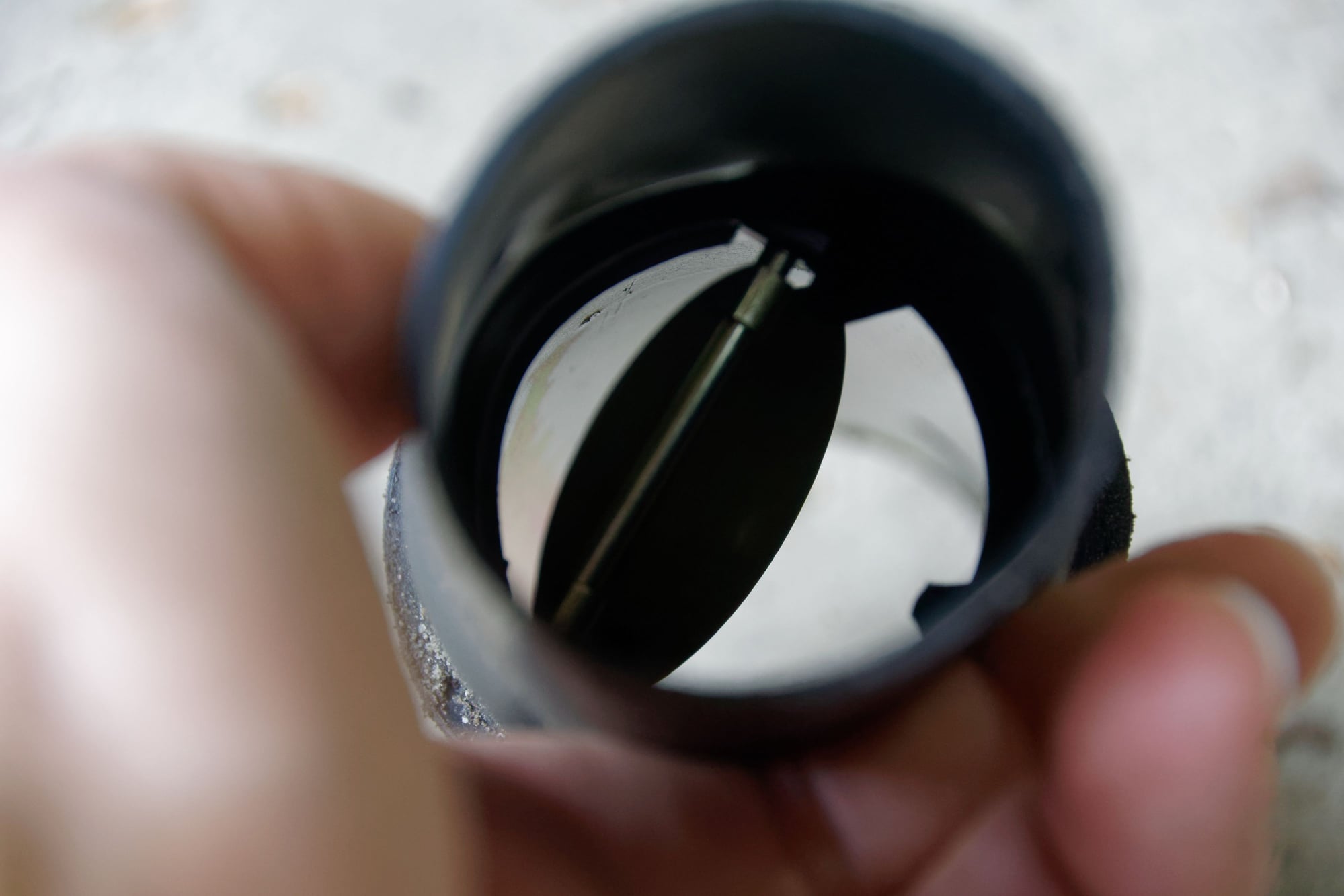
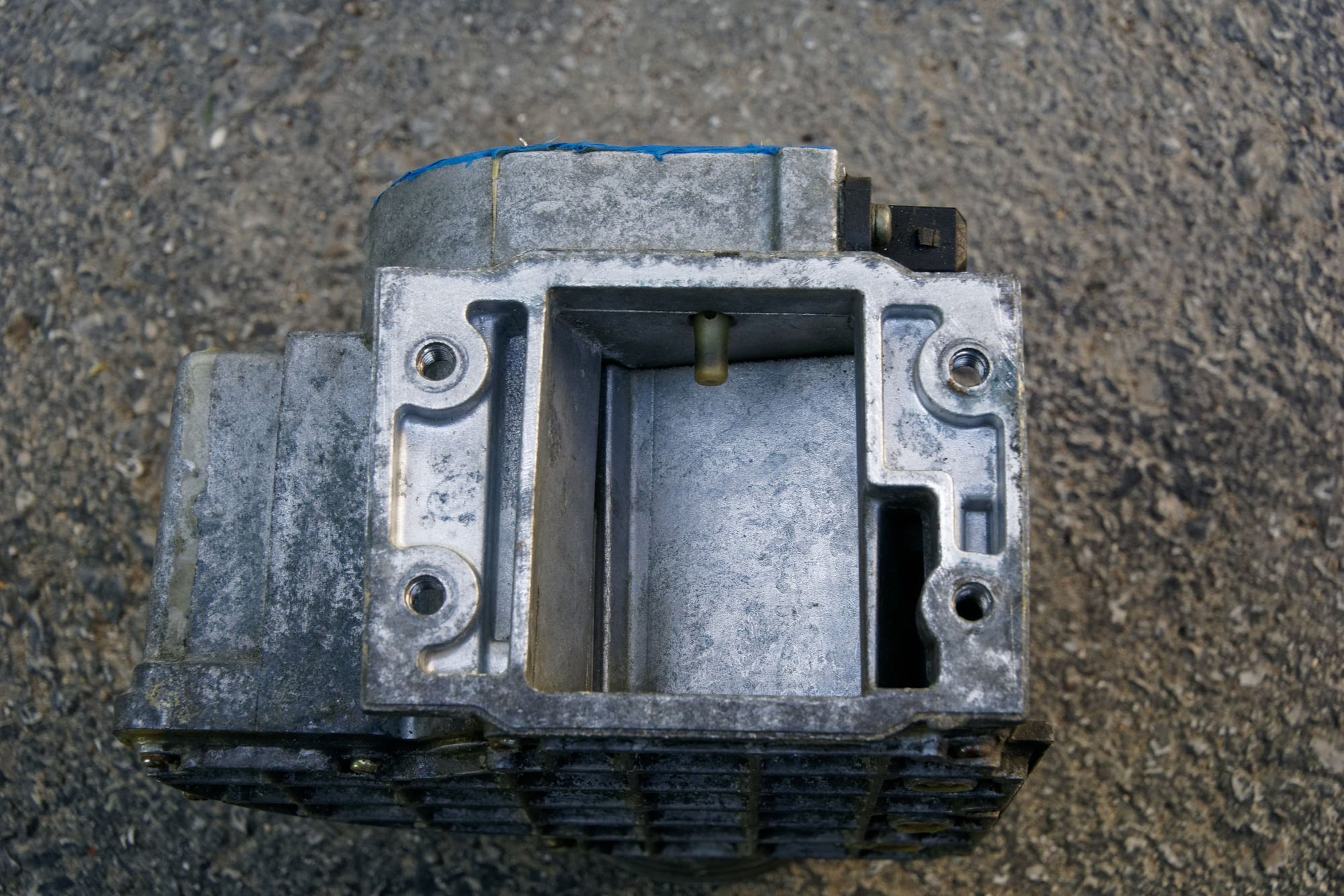
My stock pump is not in good shape though:
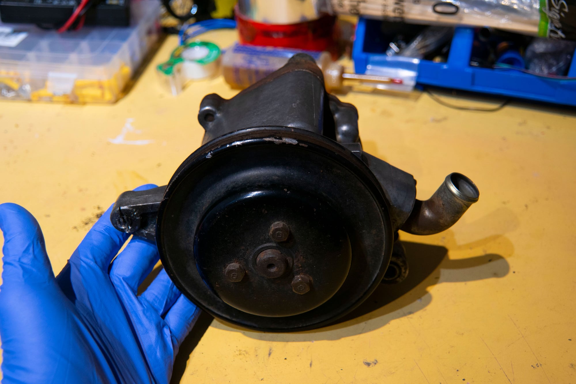
It’s a bit dirty, but the bigger problem is that there is some friction in the bearing. When I spin the pulley I can feel a couple tough spots. It also makes some pretty bad scraping noise as I turn it.
Keep in mind I had no idea how these pumps work or what I was doing. I saw some old pictures of a disassembled pump, but a few old post indicate that the inside of the pump was “not serviceable” or at least not easily. We’ll see about that.
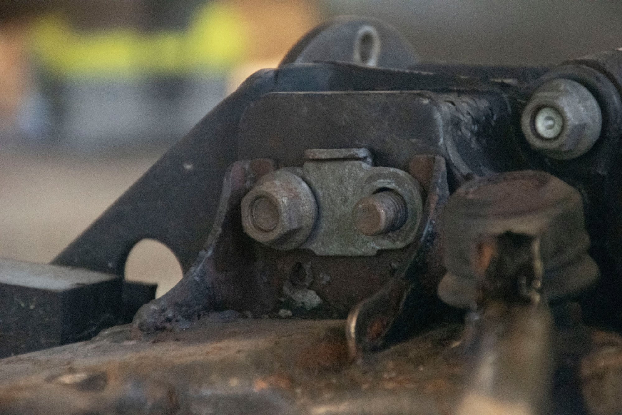
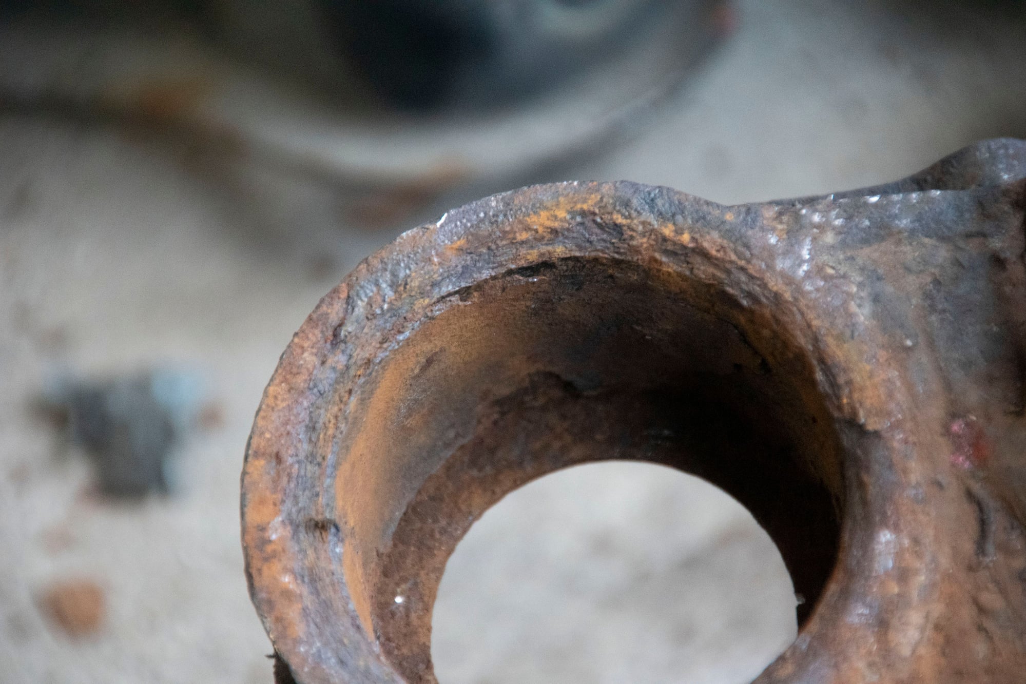
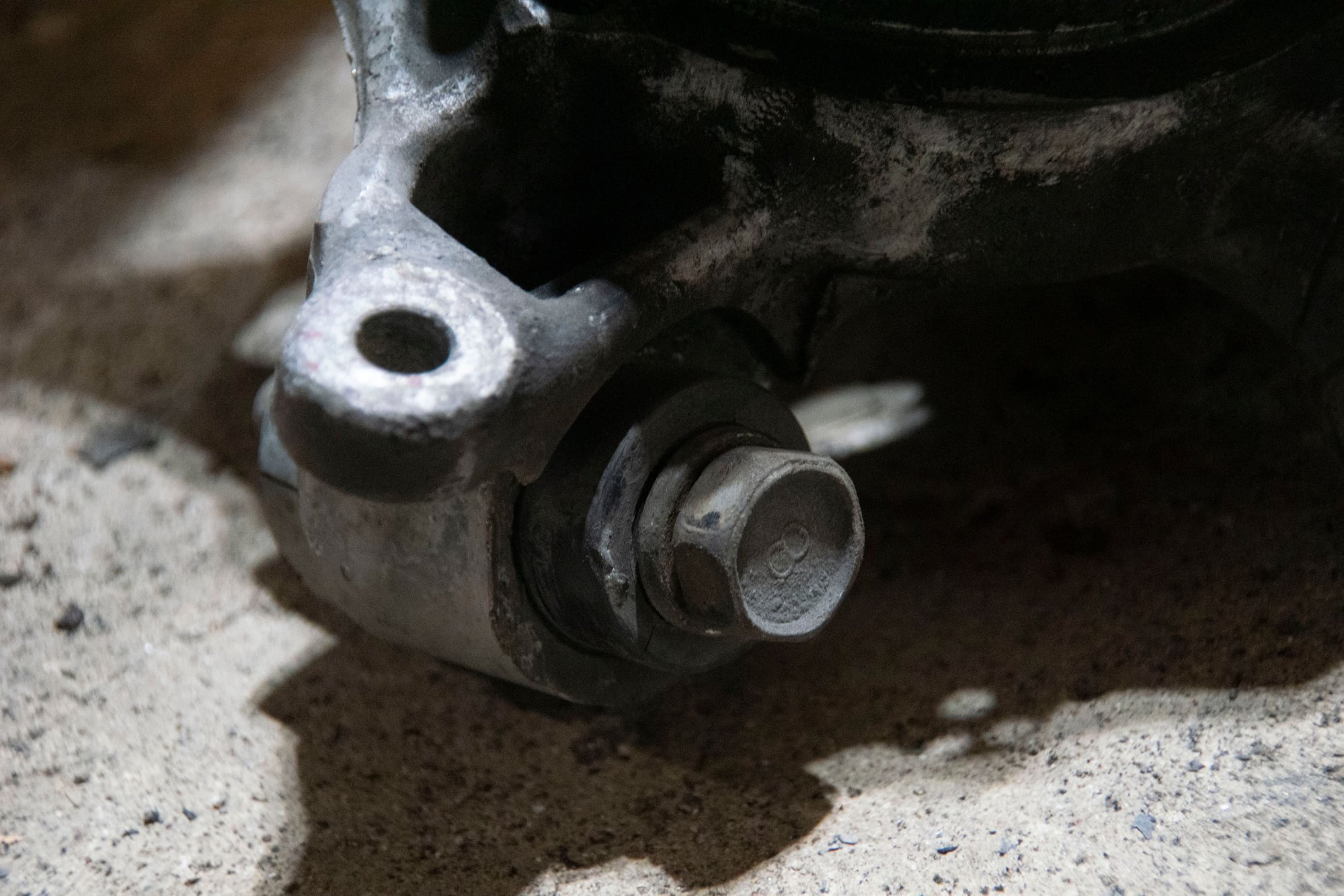
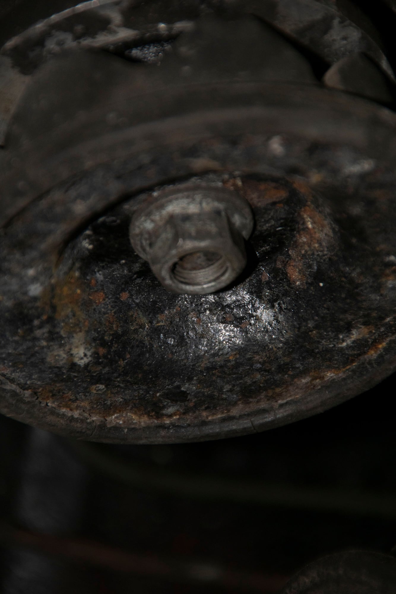
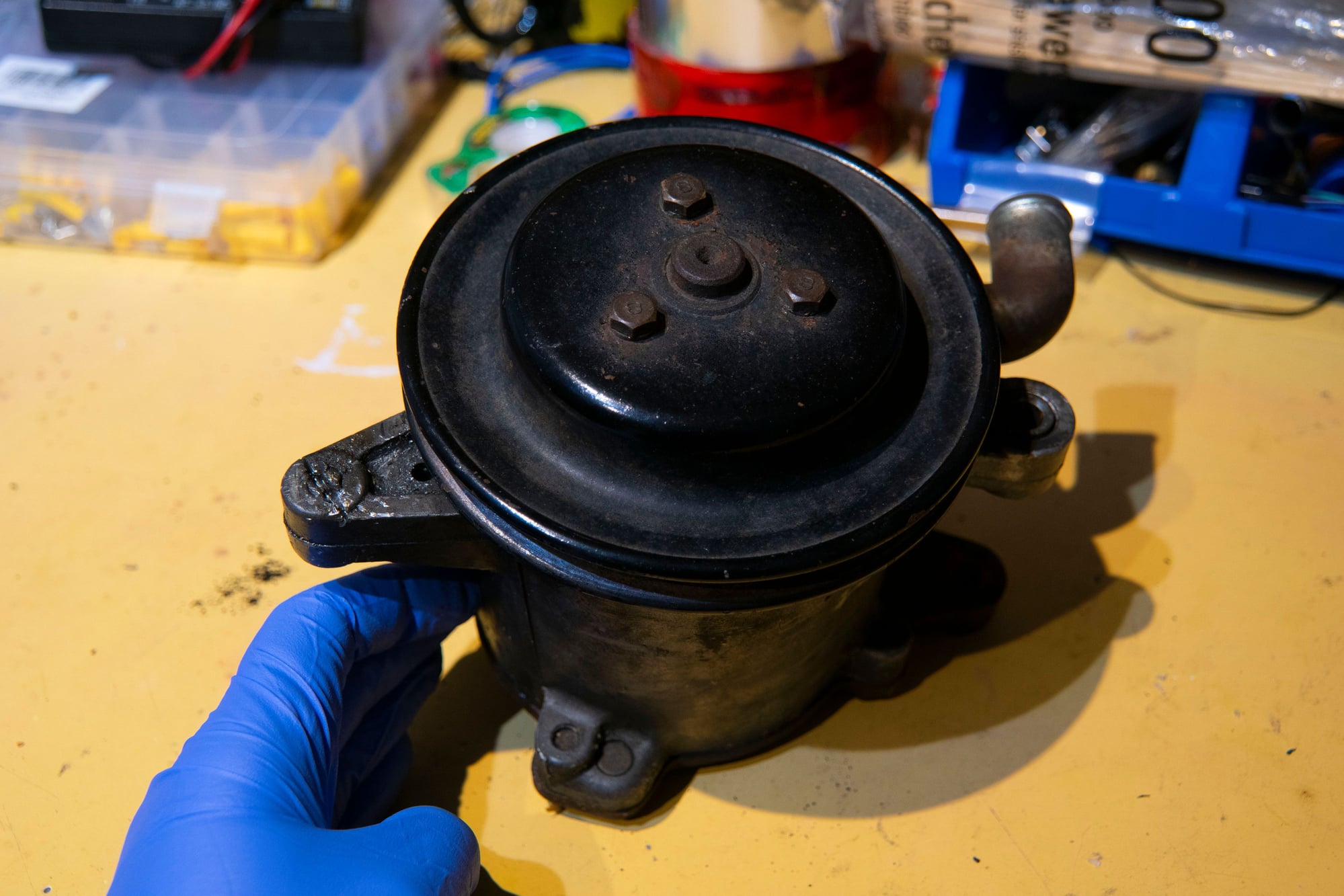
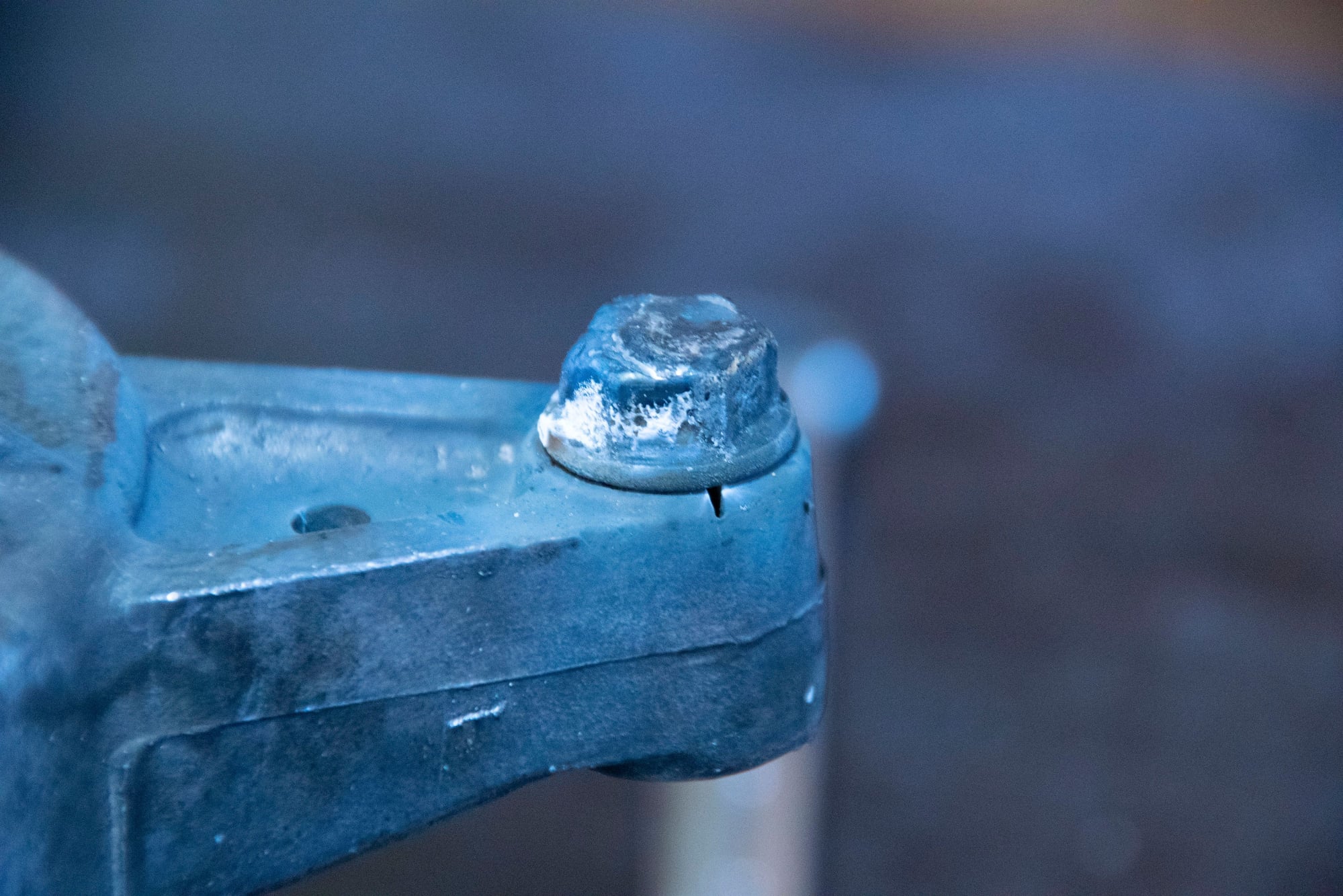
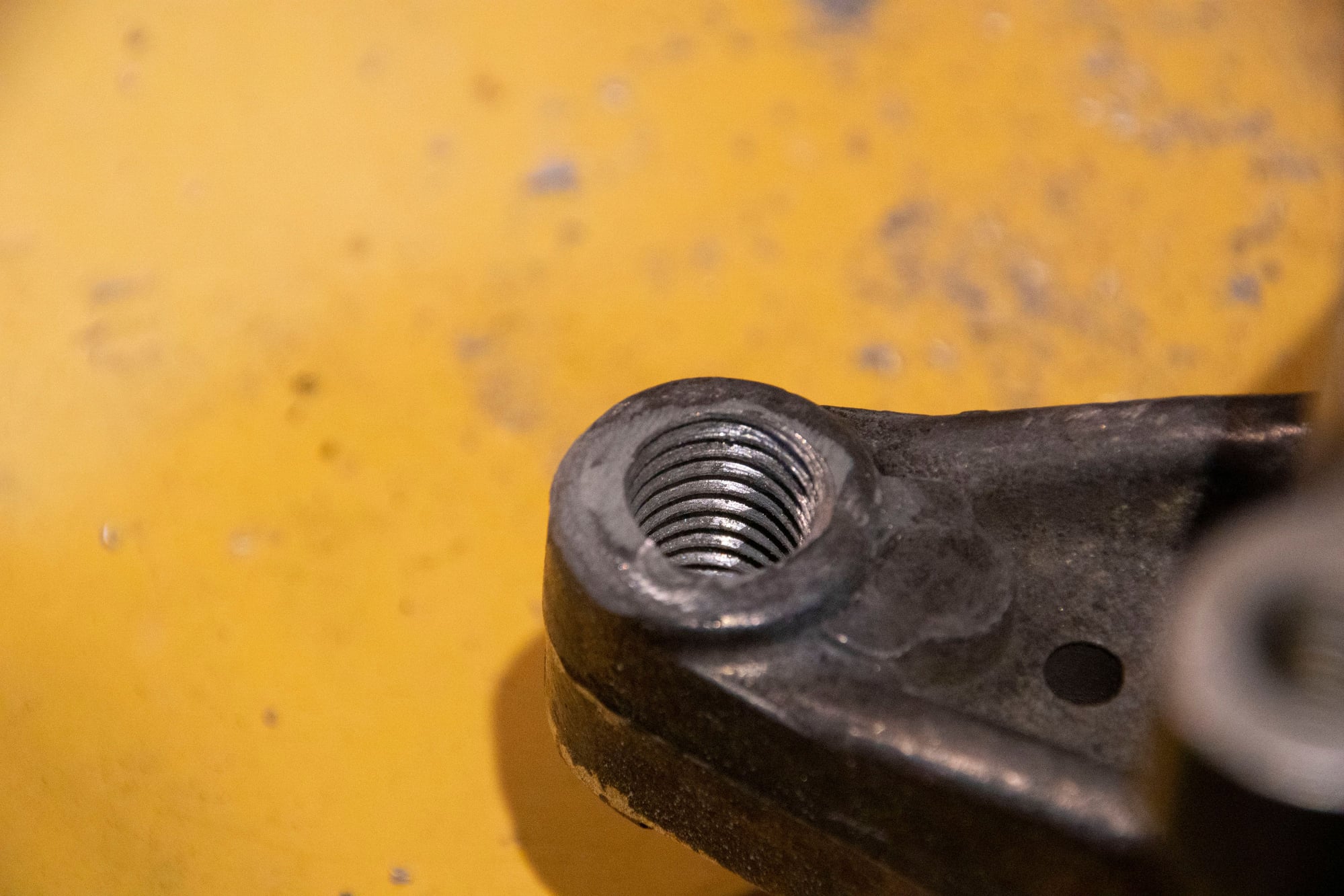
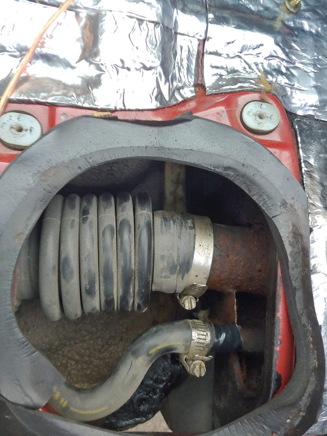
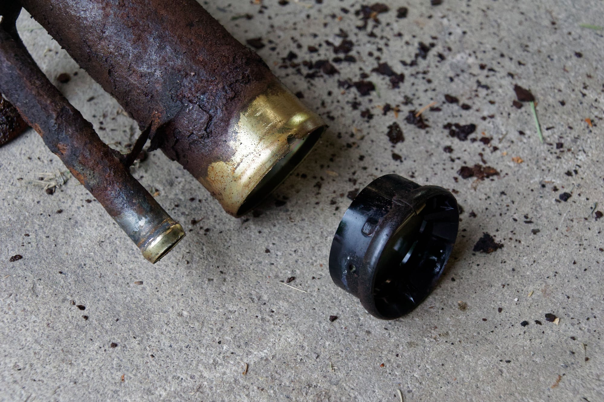
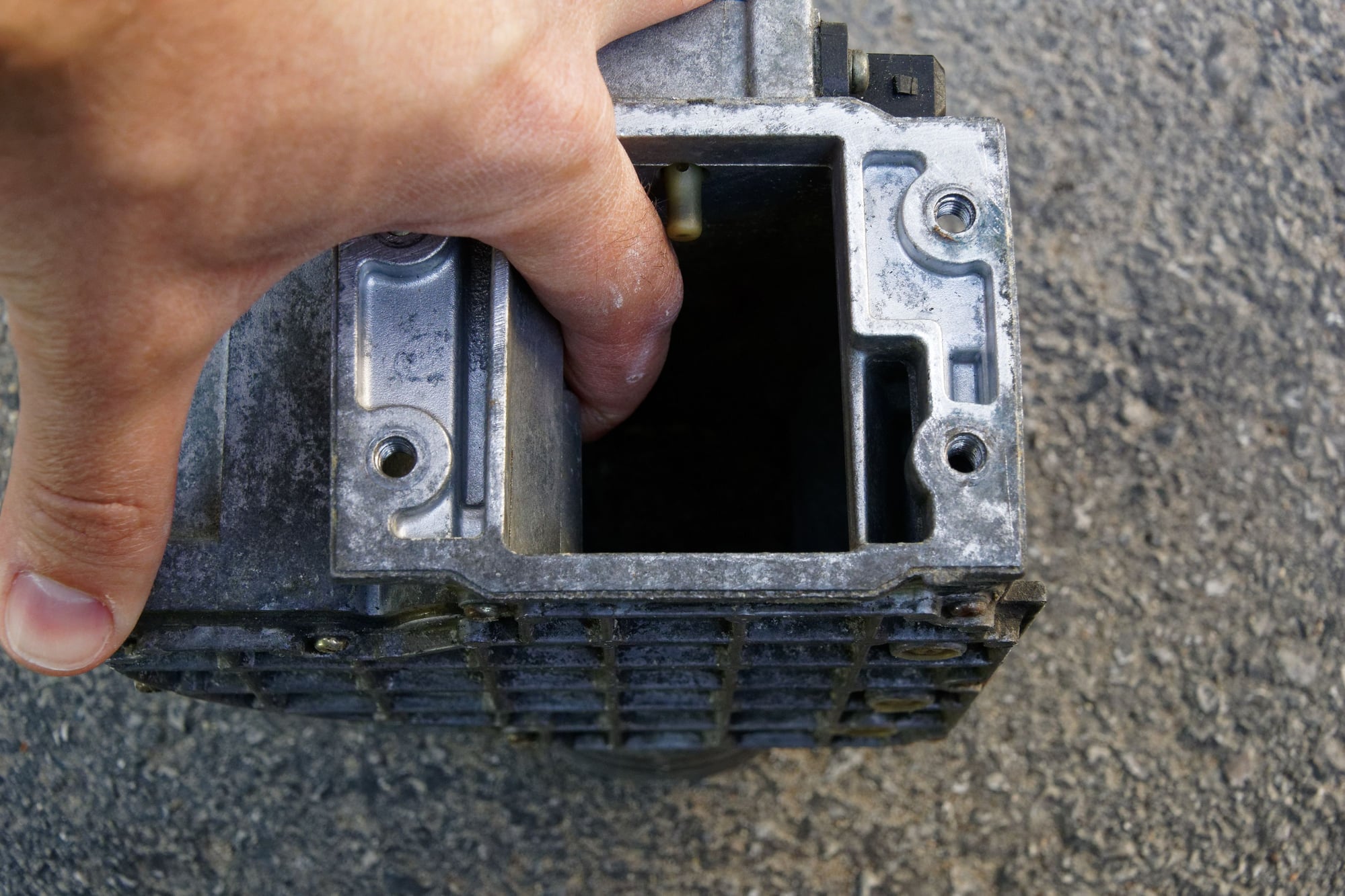
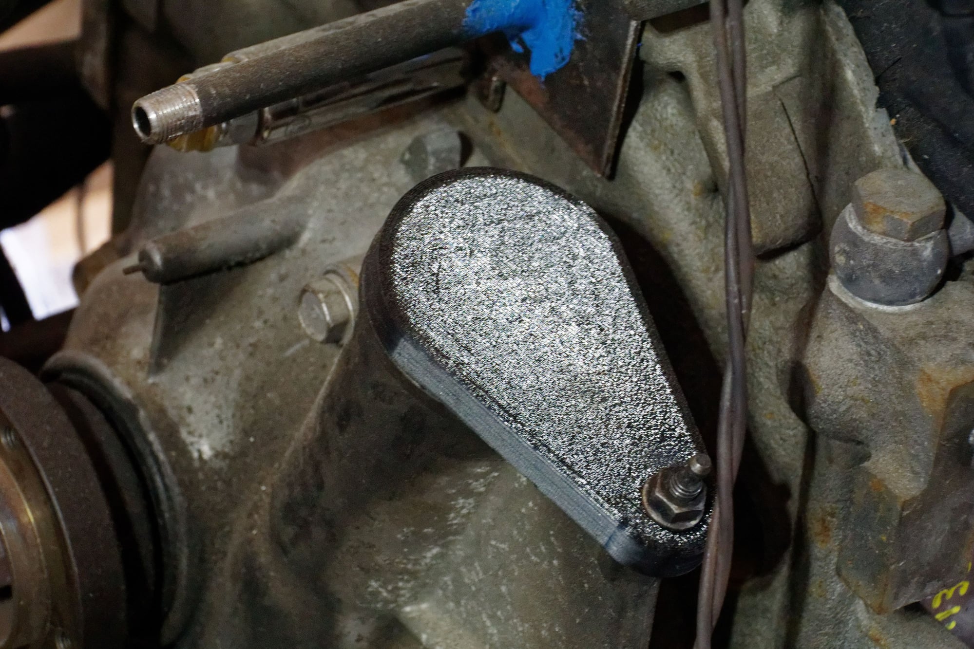
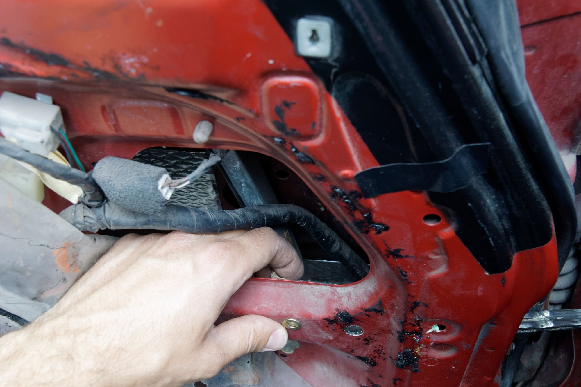
Lastly, there’s the reason I initially removed it:
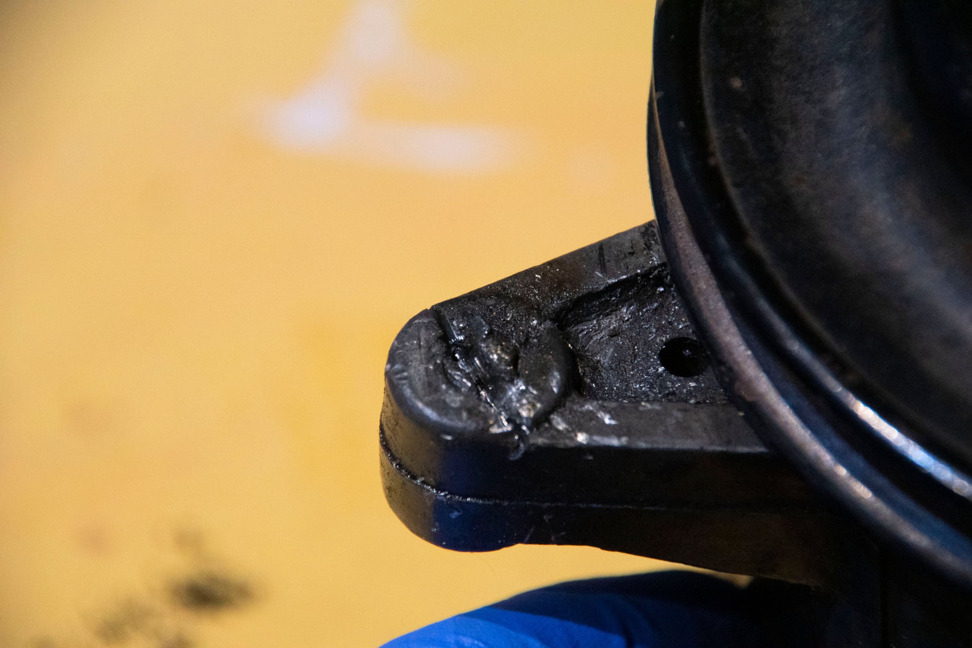
The bolt that holds the pump to the tensioner arm snapped off. You can see some of the damage I caused trying to remove it years ago, but trust me, this wasn’t me being overly aggressive. That thing is STUCK in there. Extractors didn’t bite, heat did nothing, and I even slotted the bolt with a Dremel to try and use an impact driver. All I managed to do was twist the hardened impact driver bit.
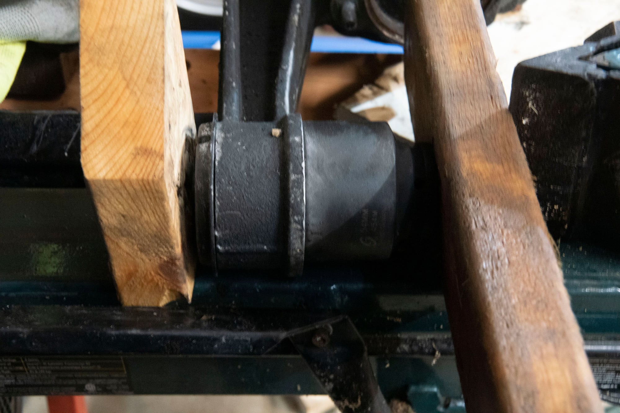
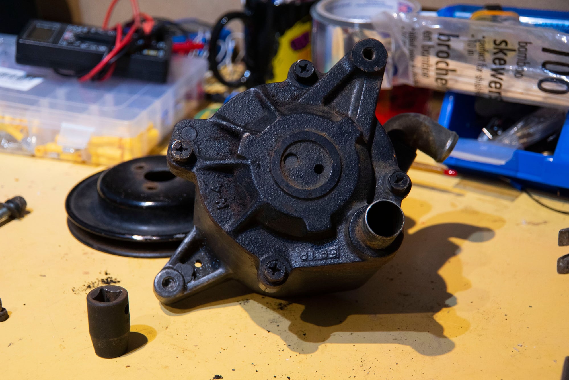
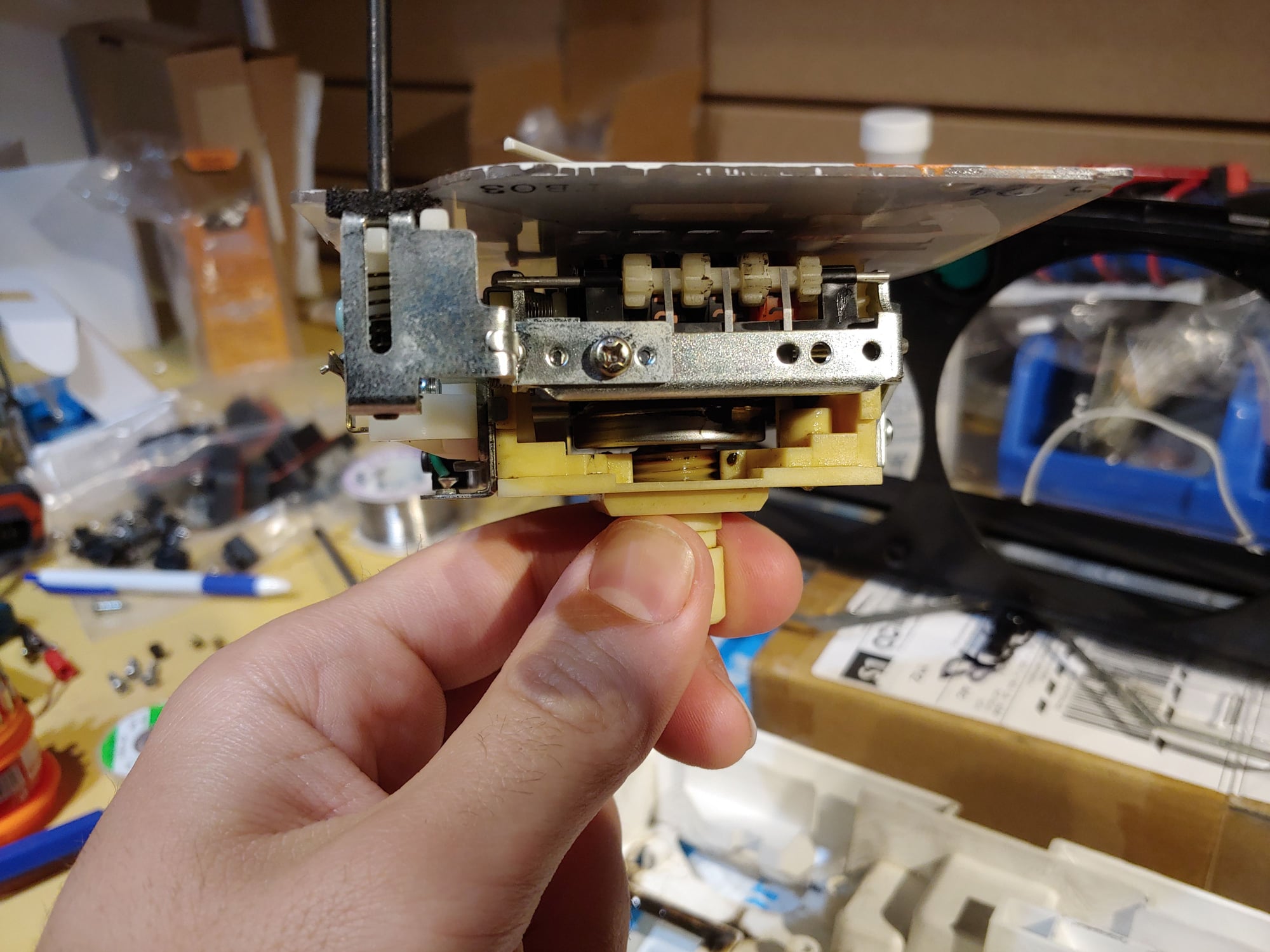
Disassembly is actually fairly simple. I expected it to be a lot worse when I read that the entire front stack is pressed together. To start, the pulley comes off of the hub with three bolts:
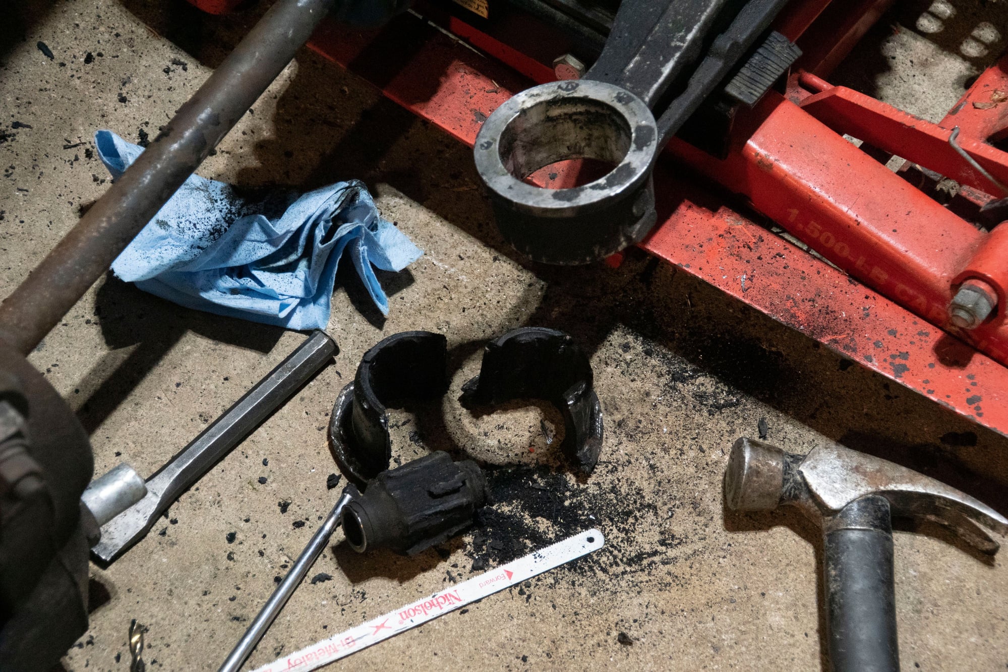
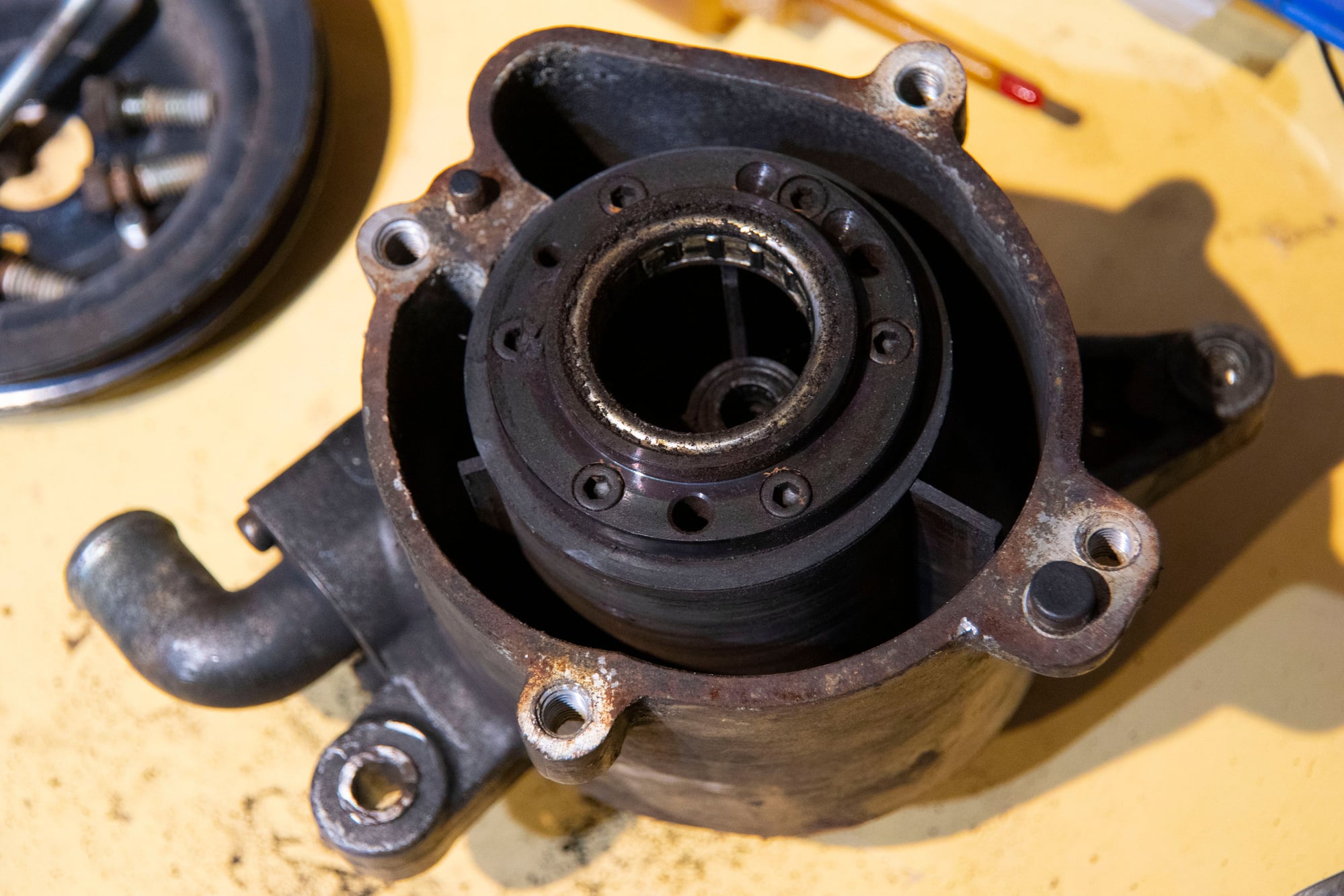
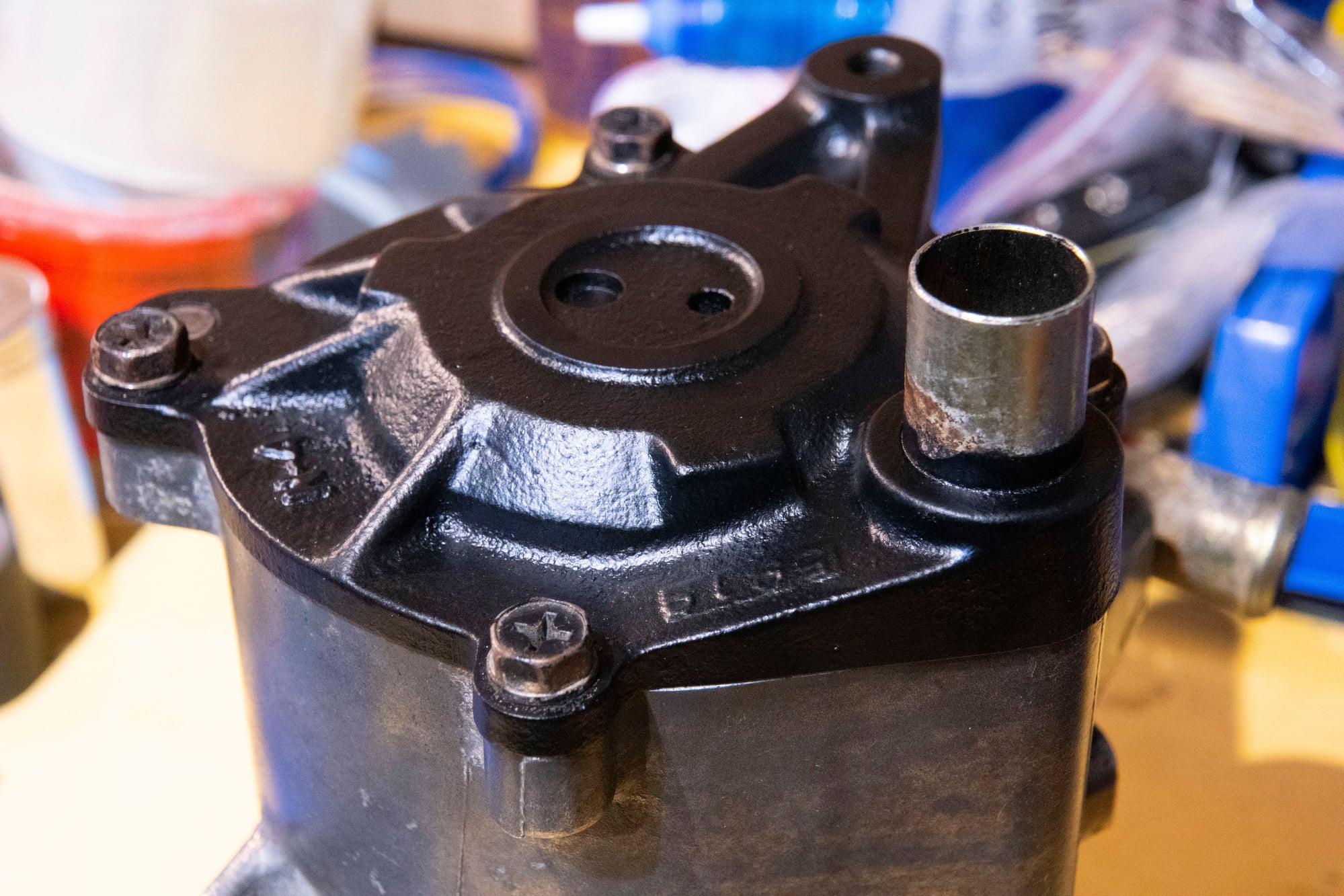
Then there are four 12mm bolt that hold the cast-iron back plate to the aluminum housing.
The two locating dowels can make it tough to remove but a hammer will free it. Be sure not to damage either of the machined surfaces or the dowels themselves.
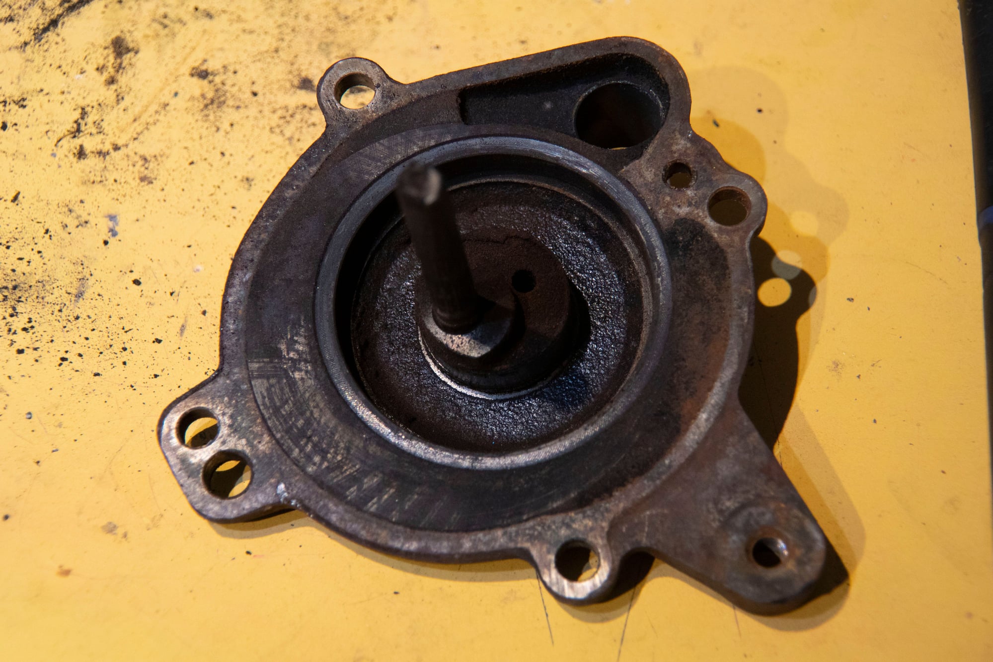
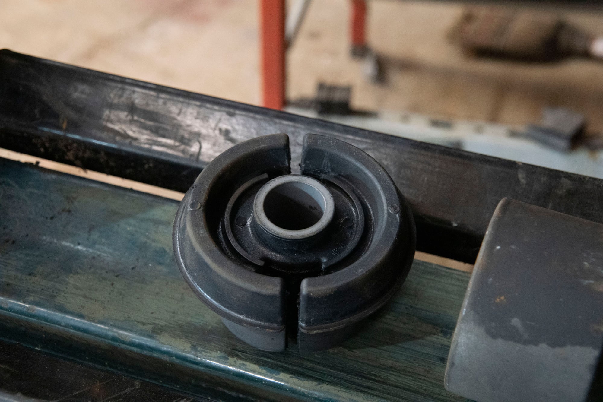
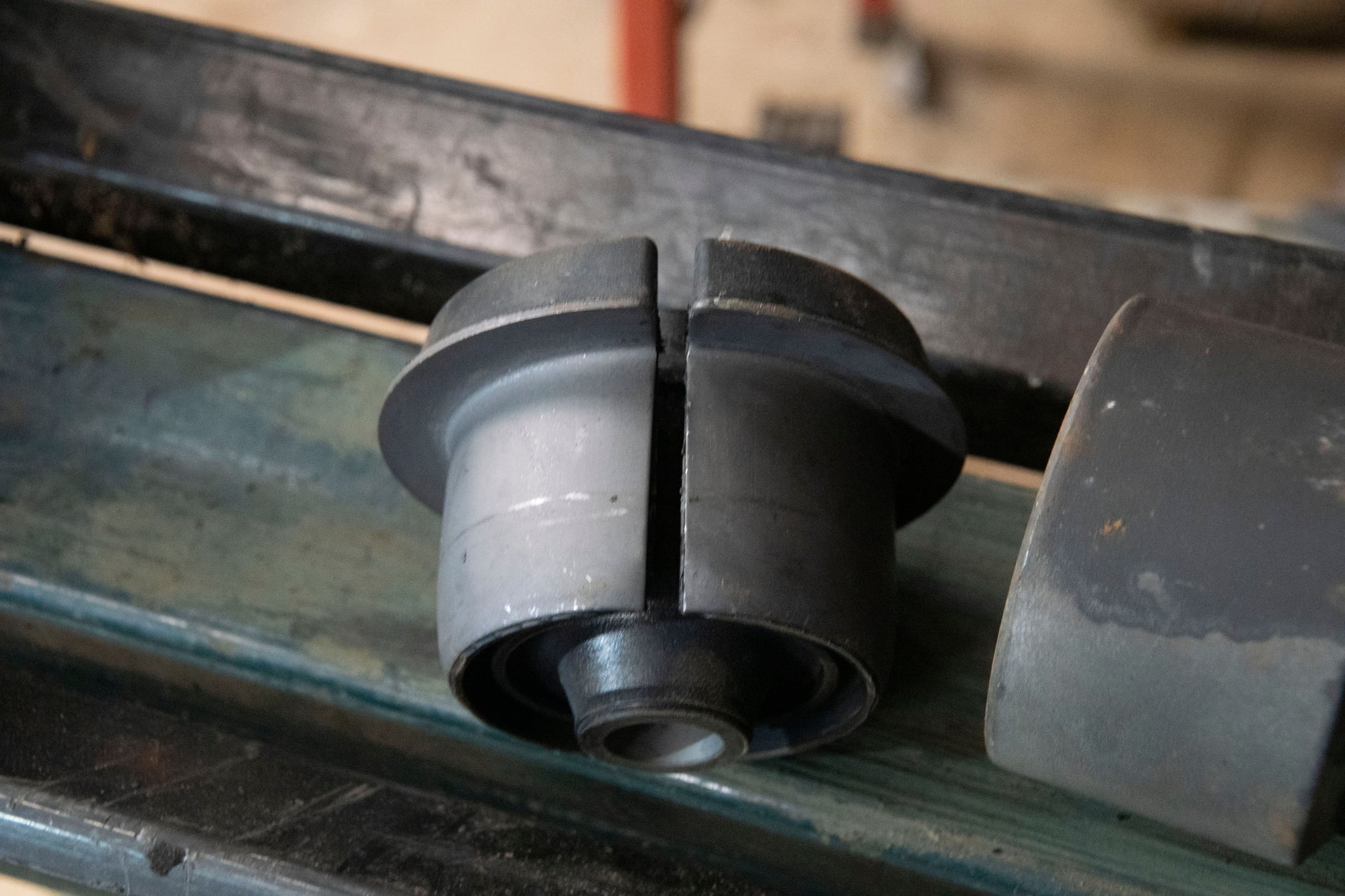
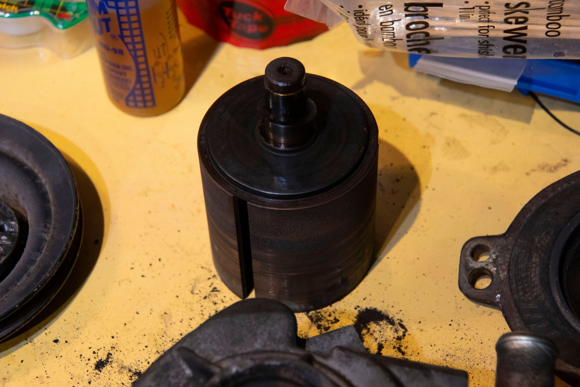
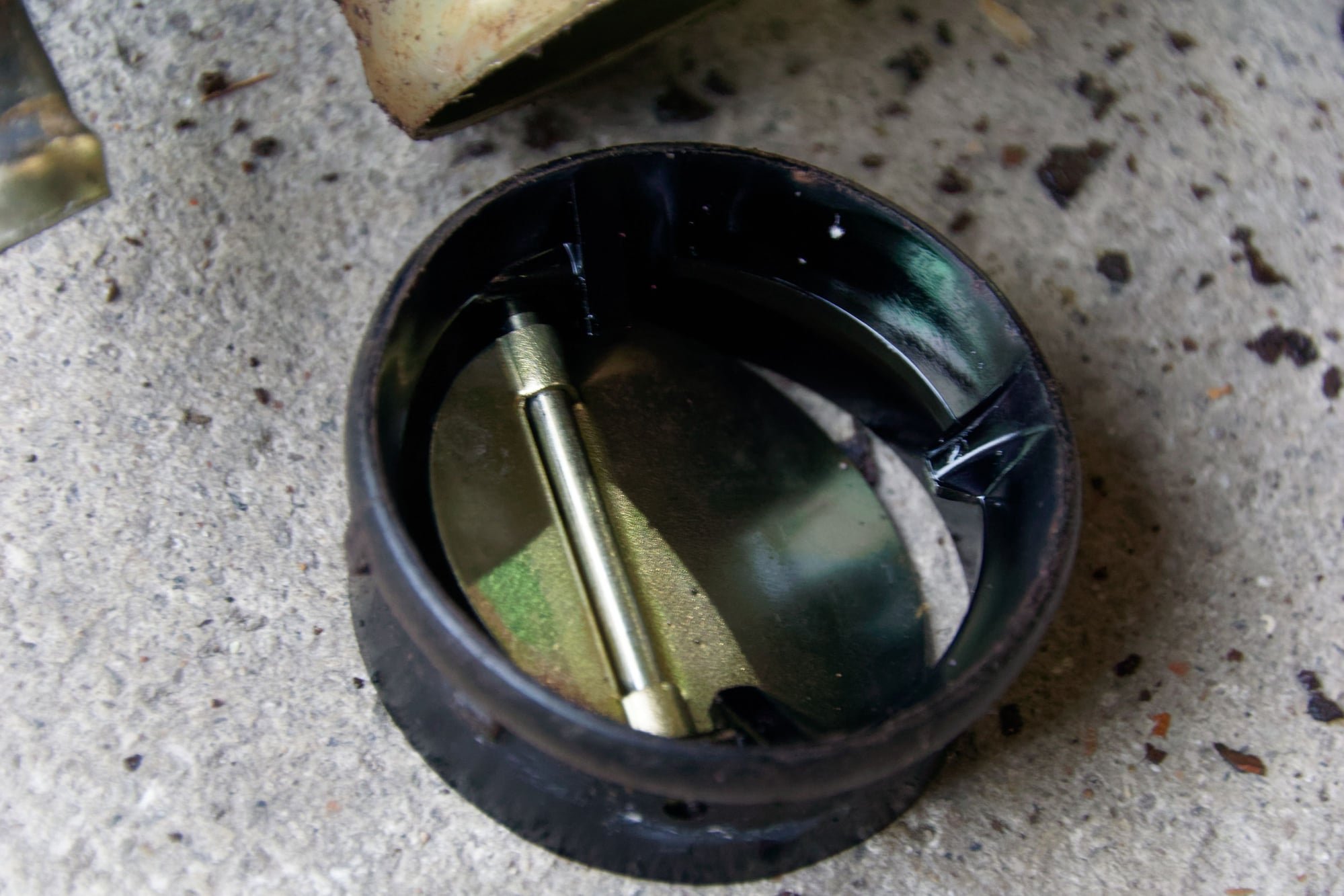
Once it’s free we can see this spindle thing. I don’t know the technical name, but the bottom surface (race?) is concentric to the pulley and the spindle is offset. It’s really neat how this works, I’ll get into that a bit later.
If you’re using this as a guide, make sure to take alignment marks from here on out. Everything inside the pump is balanced, and wears together. I don’t know exactly what happens if they’re out of balance but I’m not eager to find out.
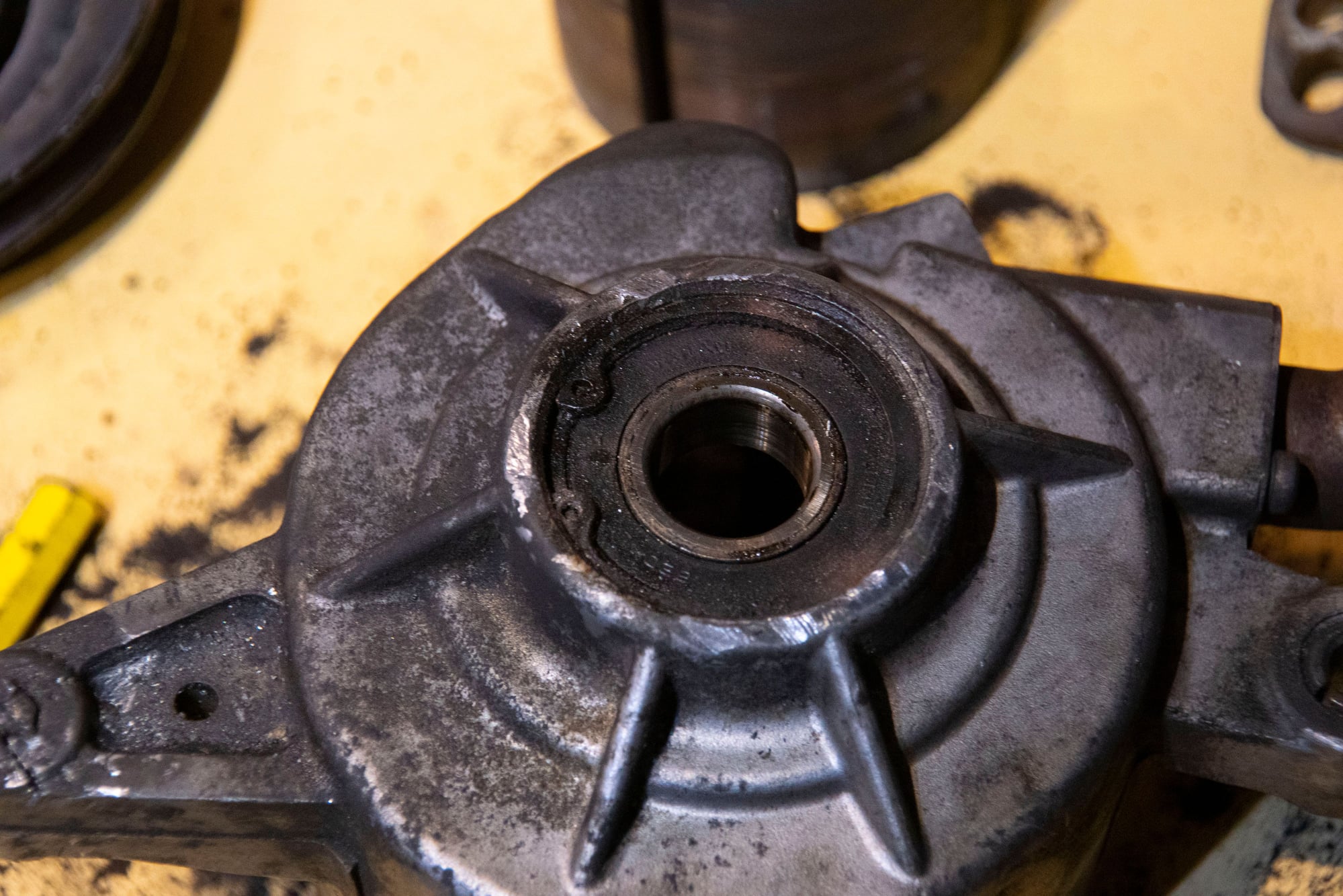
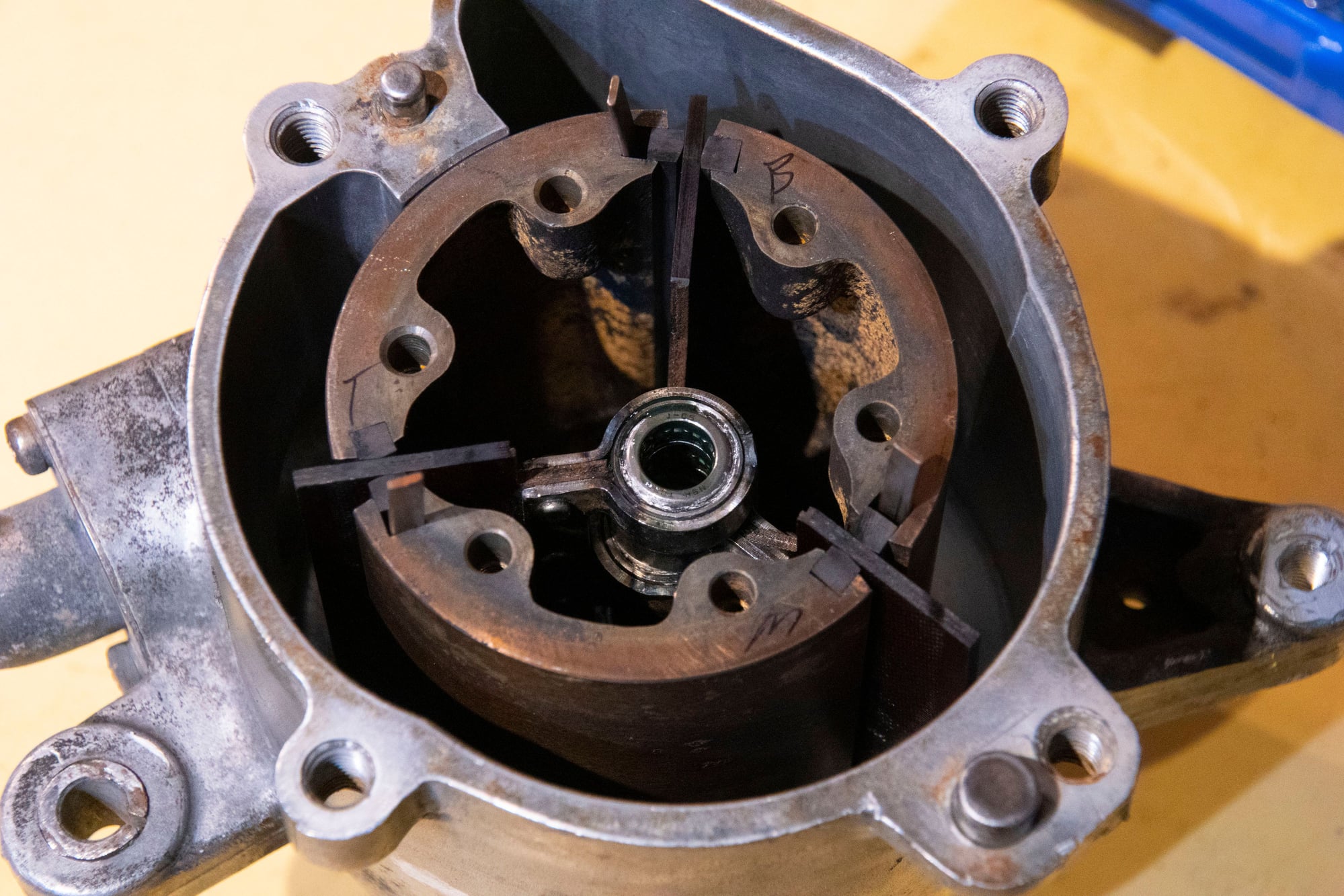
The inside has this plate with balancing marks on it and a central bearing:
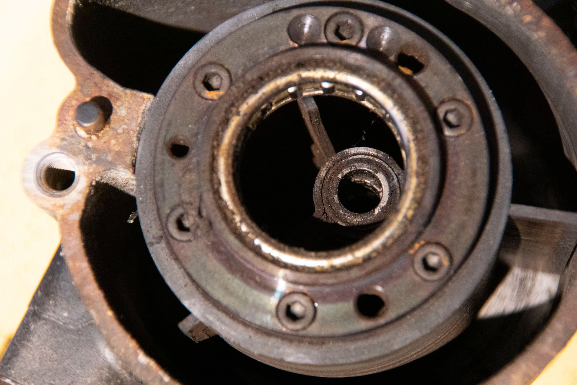
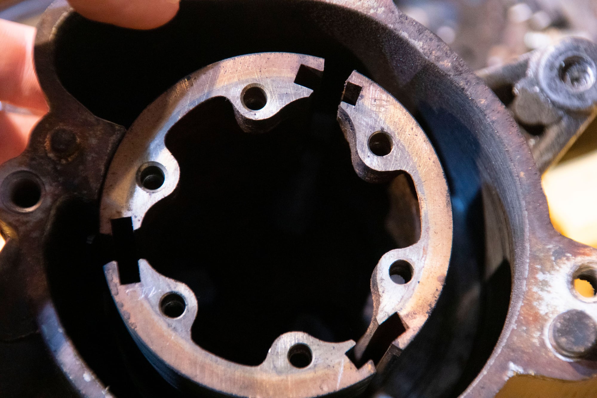
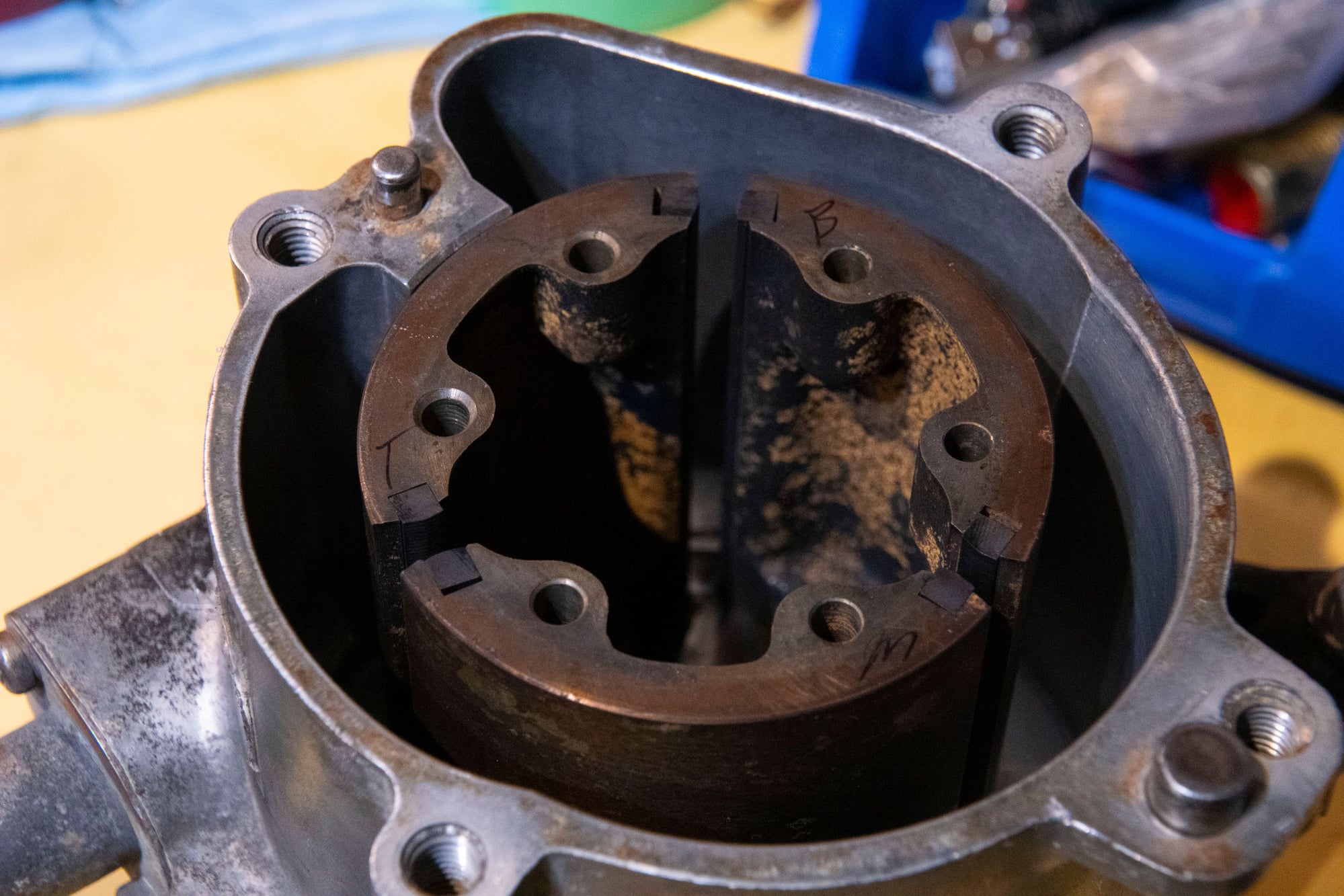
It comes out with 6 hex bolts. I put it aside after noting it’s alignment, and now we can see how the pump works inside:
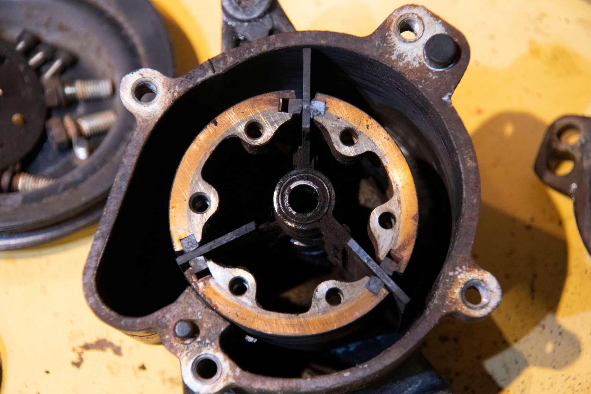
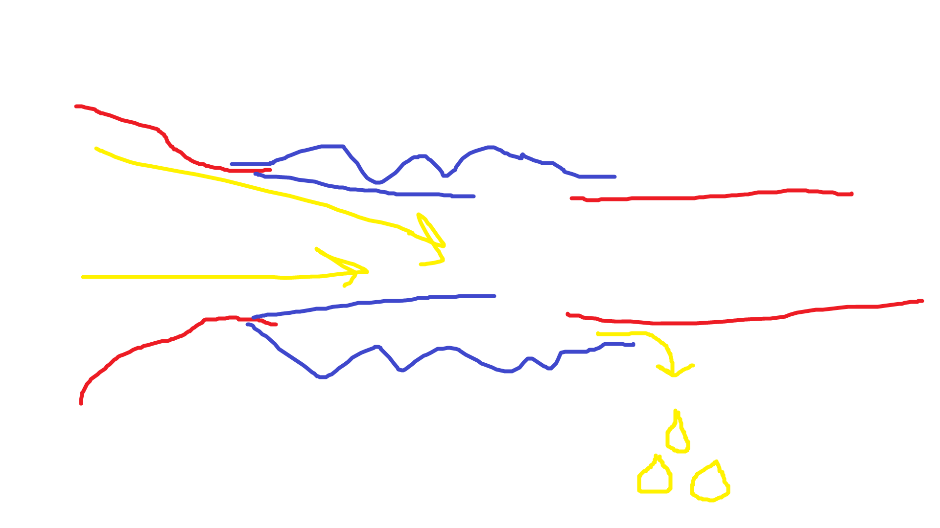
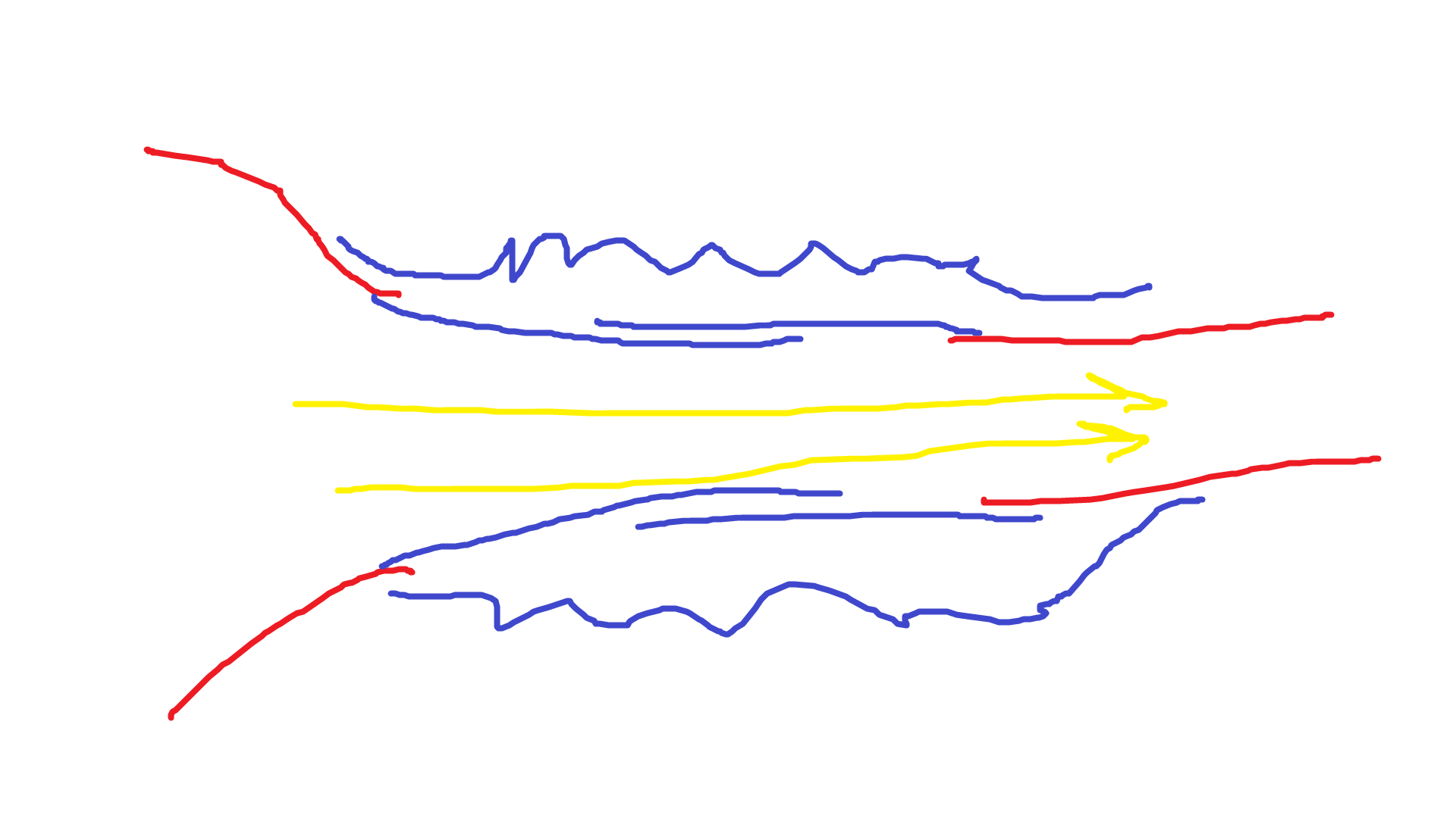
There are three vanes, each made of some sort of plastic (phenolic I think). Then there are these graphite-feeling seals on either side of them, one of them sprung. These vanes ride in a round cutout at the bottom of the aluminum housing (sorry, forgot to photograph the empty housing) concentric with the pulley, but their clearance to the housing is actually dictated by the shaft on the back plate.
The shaft sits offset from the center of the housing so that as the inner rotor spins, the vanes move in and out. They first move outwards on the intake side of the housing until they touch the housing itself, forming an enclosed chamber around the intake air. Then they spin around to the outlet side and pump the pressurized air out, before retracting back into the rotor. They pull all the way back into the rotor to sweep past that little wall dividing the sides of the pump before beginning the cycle again.
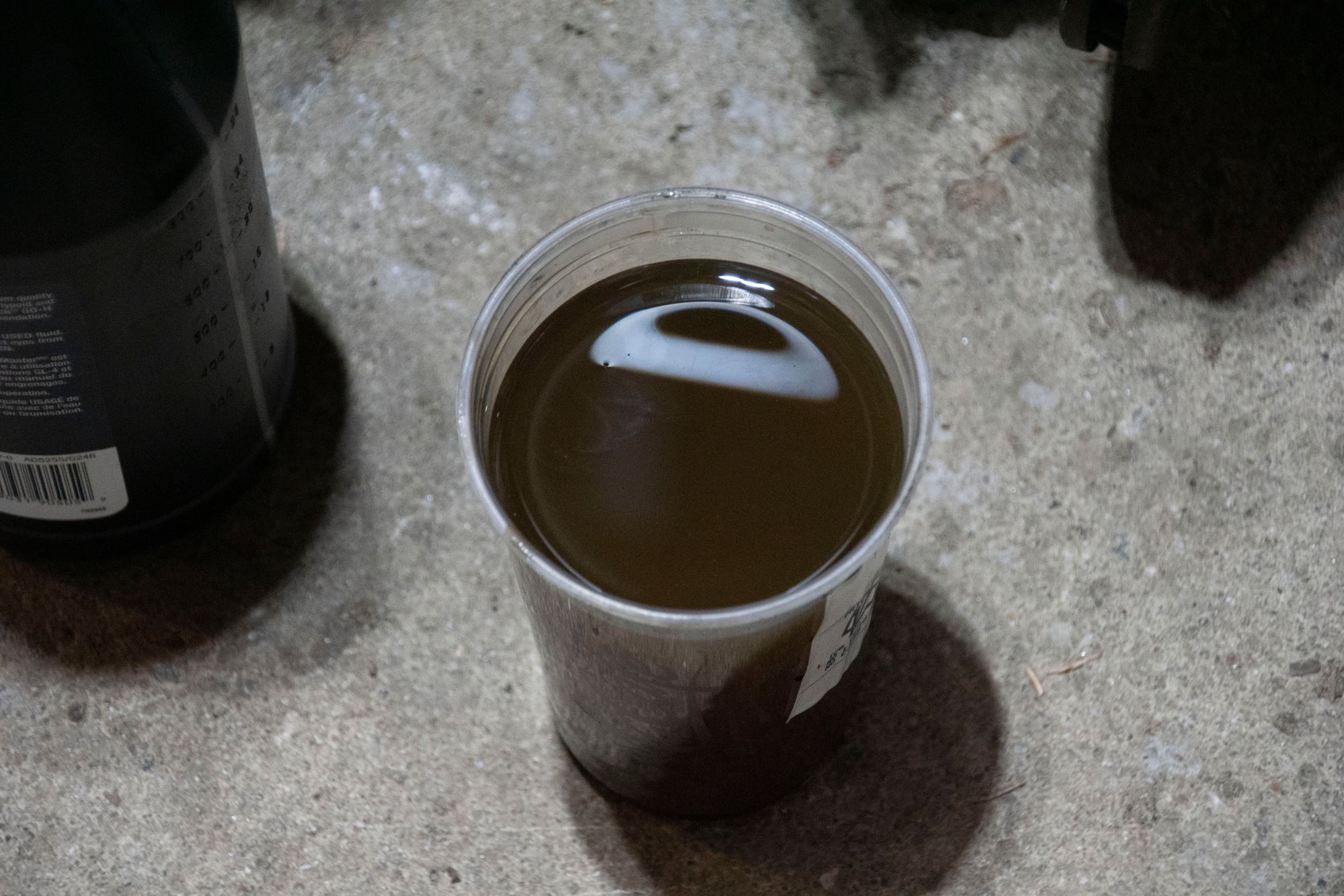
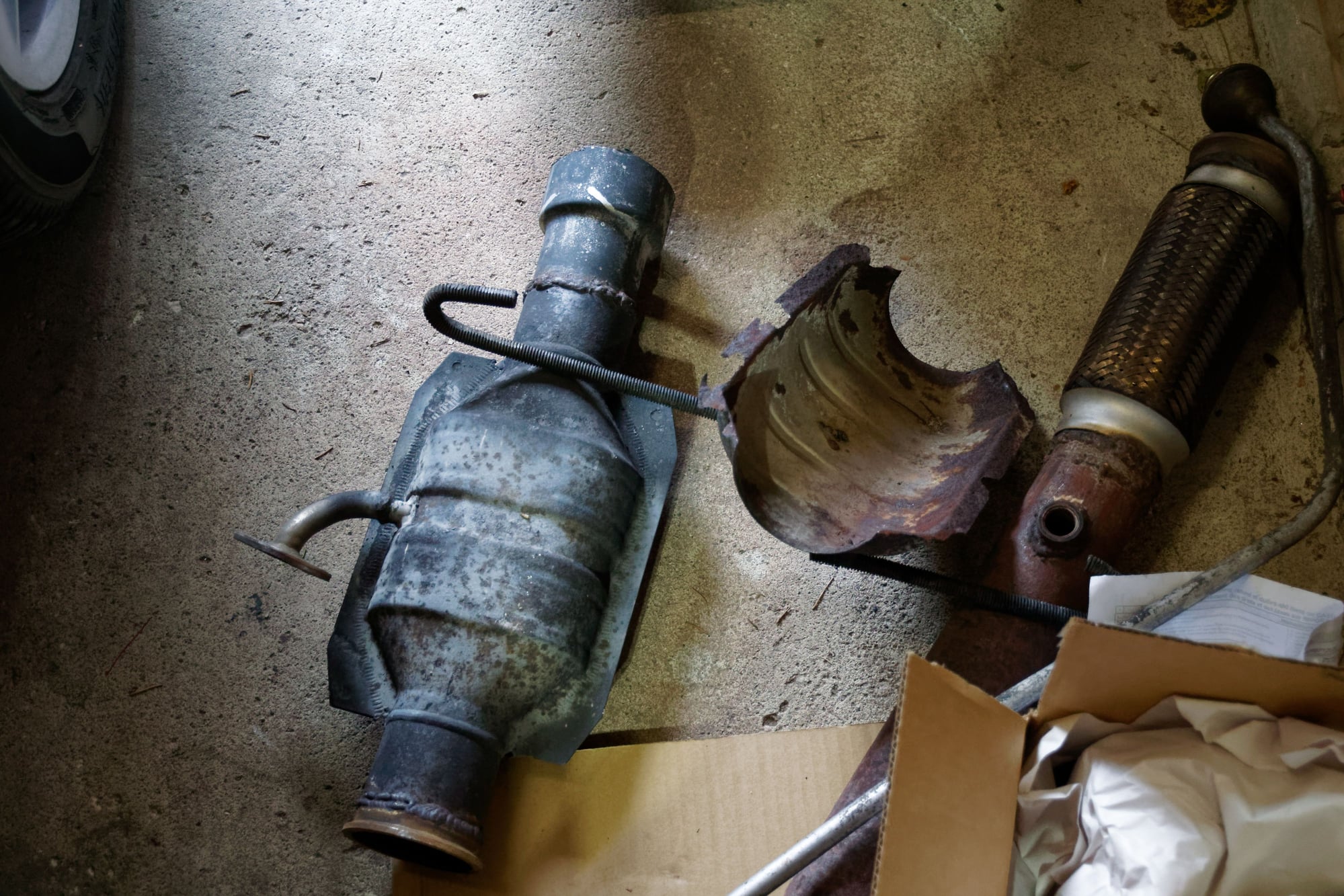
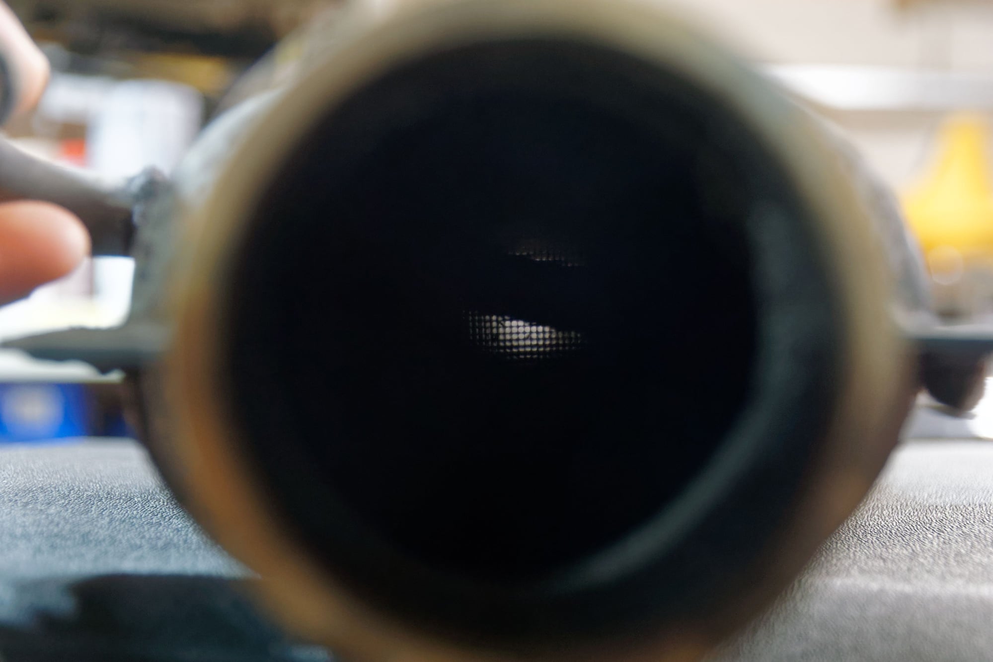
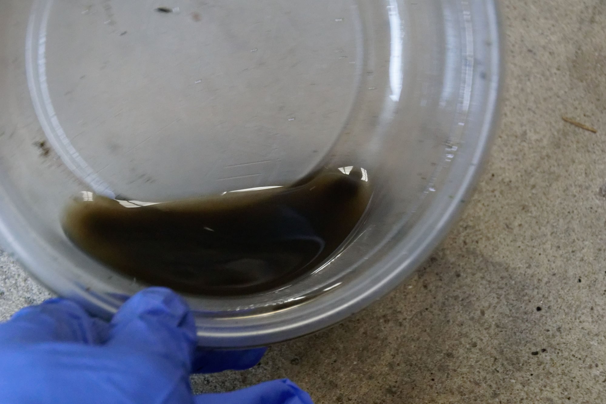
I know it’s just a simple rotary vane pump but I still find it neat. The problem with my pump is that it's full of crap:
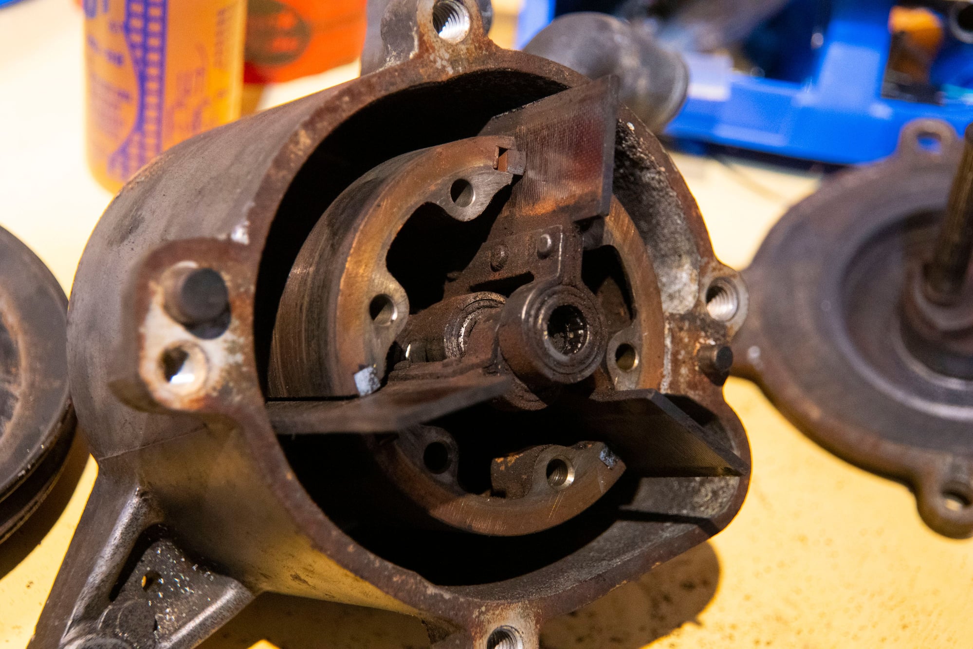
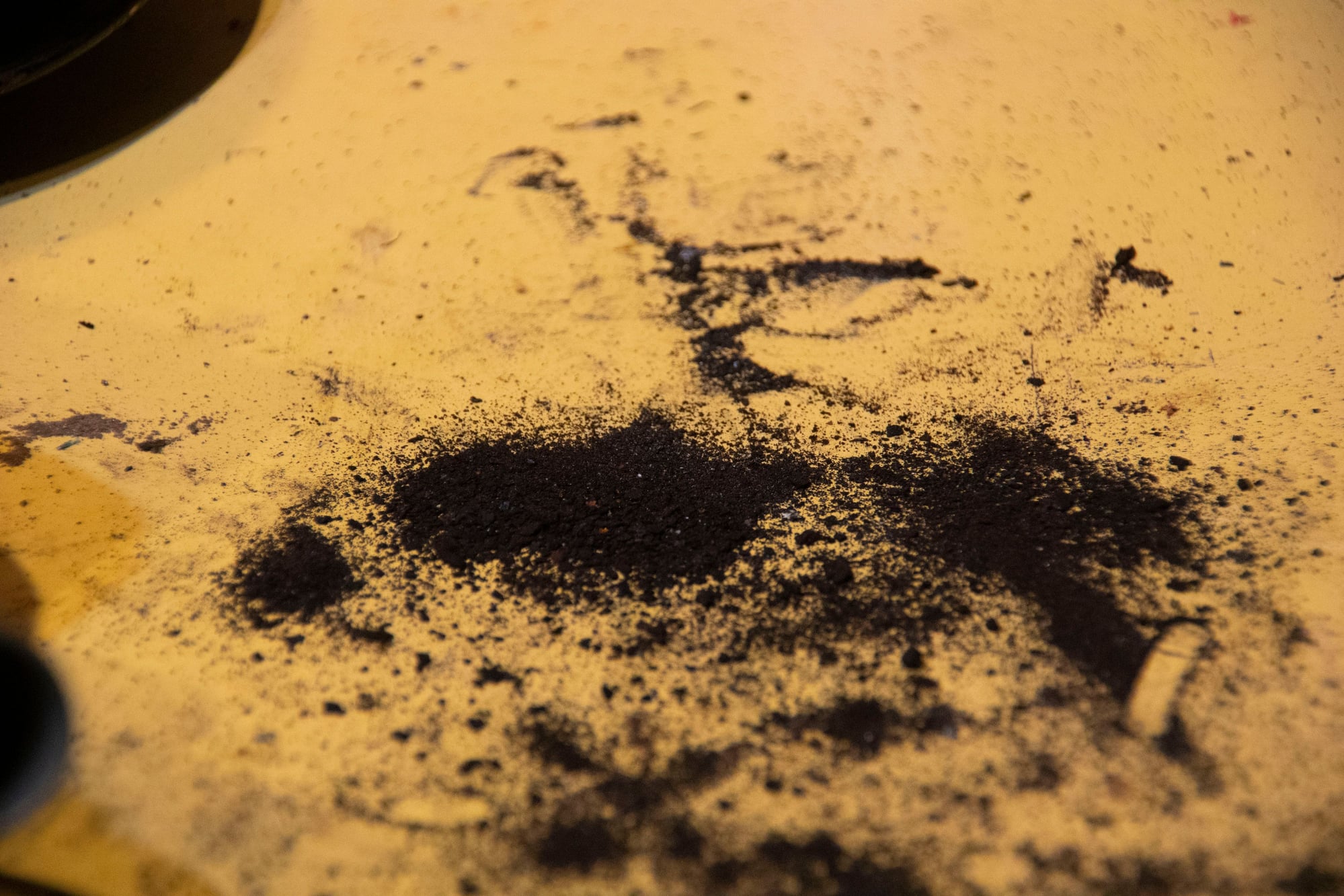
Most of it looks like soot, which likely means the ACV I had on the car before wasn’t sealing very well internally and exhaust was somehow backfeeding into the pump outlet. Maybe the catalyst being clogged caused the pressure in the exhaust to exceed the pump outlet pressure? Who knows.
The pump also sat in the shed for a couple years in a box, which likely didn’t help it any.
On disassembly I was careful to note down the position of every part and put it back where it came from. I also noted the orientation of all the seals and kept them as matched sets.
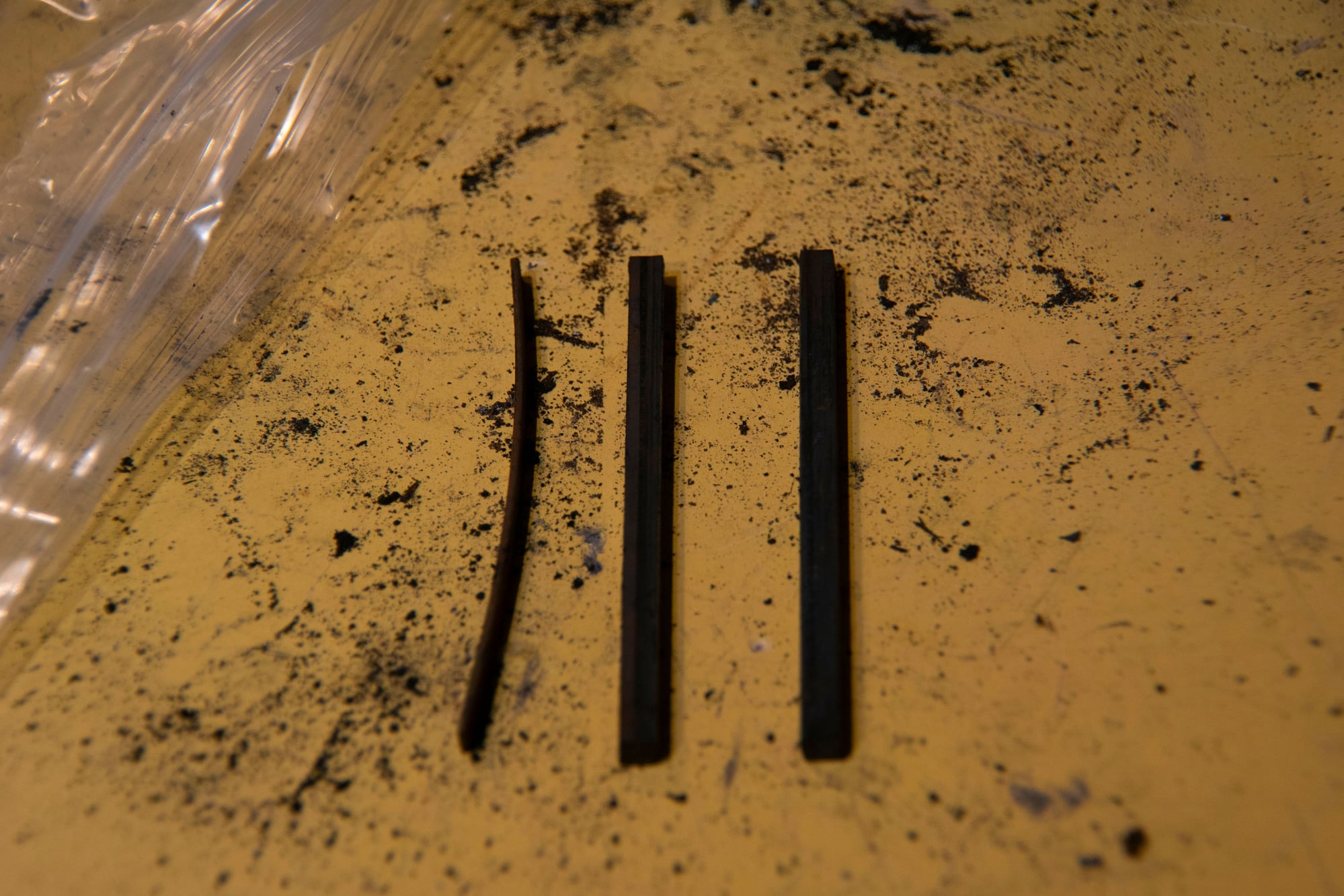
Not dissimilar from the apex seals and springs actually. I guess it’s more like two apex seals, one unsprung, sealing laterally against a third apex seal driven directly by an e-shaft? The analogy kind of breaks down here, but it’s kind of fascinating that the inside of the air pump uses many of the same principles as the rotary engine itself.
With all of the insides removed other than the rotor, I first turned my attention to removing the hub. It’s pressed on, but some heat and some careful levering with a chisel freed it without too much difficulty.
Then I gently tapped the rotor on it’s end to remove it from the housing and set it aside.
Lastly I removed the big circlip and then tapped the bearing out. For anyone considering a similar rebuild:
- The front bearing is a common one, NTK 6204. I was able to get two replacements from Timken for about $12 each.
- The rear bearing is unobtanium. NSK DB-36227. I was not able to find any replacement options, but luckily this one is a non-sealed design and mine was serviceable.
- The small bearings in the vanes (six total) are NTK J-25. I read that these are available but mine were in good condition, so again, I chose to just service my existing ones.
Servicing them starts by removing all dirt. Brake cleaner would do it, but mineral spirits and the ultrasonic bath makes it much simpler:
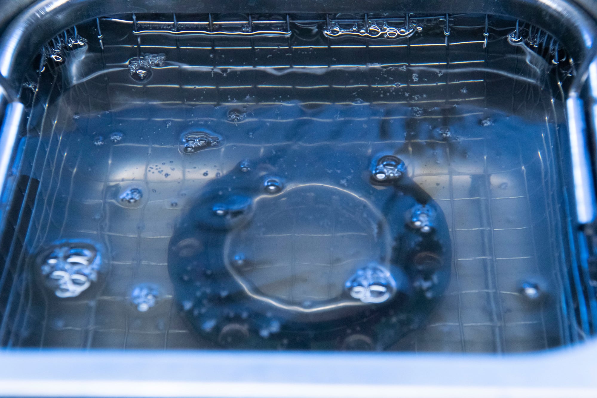
Then I finished with brake cleaner to remove any remnants. The vanes and seals all got the same treatment, cleaning only one or two parts at a time to avoid confusing where they are supposed to go for reassembly.
Removing the broken bolt was a nightmare. That one task probably took longer than the rest of this project combined. My first thought was to weld a nut on top, but after multiple attempts the weld would always break before the bolt would start to spin.
Then I thought I would use an extractor. I drilled through the bolt and got the extractor started, only to thread it in really far and then snap it off. Now I had a hardened extractor stuck inside the shaft. Great!
I decided the next step would be to just drill through the remains of the shaft until there was almost nothing left and then tap for a larger size. Unfortunately the drill bit also got most of the way through before hitting the extractor and breaking off. Now there was an extractor and a drill bit stuck in it…
So I ended up going medieval on it. I basically started drilling away at the bolt, and then once I had drilled away all I could get the bits to bite into I started drilling away the aluminum around the bolt.
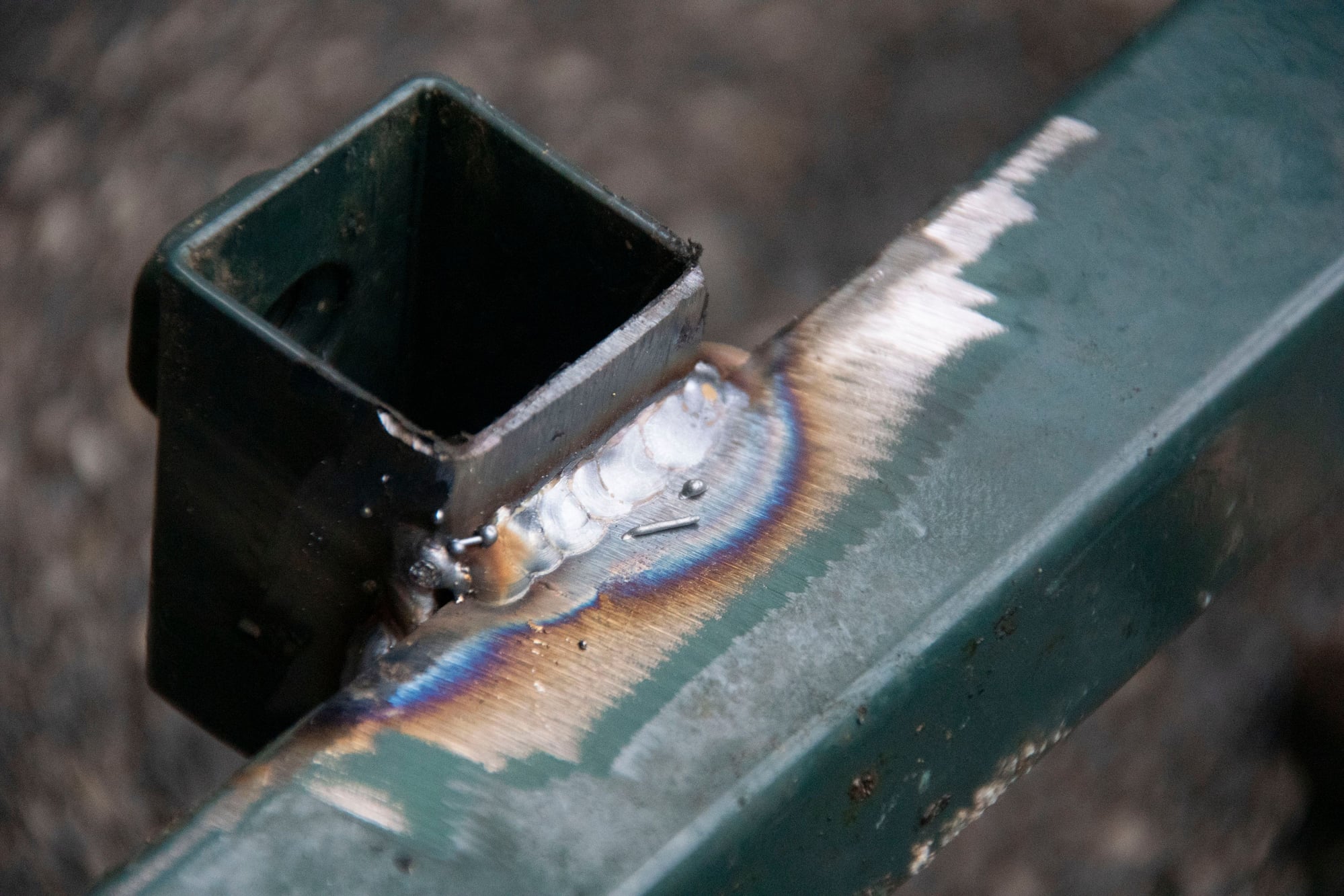
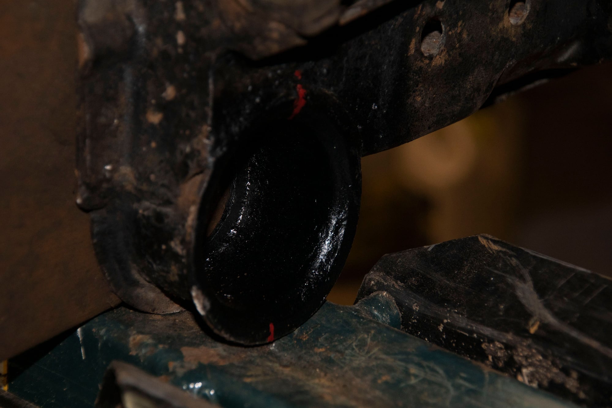
Eventually I welded another nut on, and I could feel it starting to snap my welds when the broken bolt finally cracked loose:
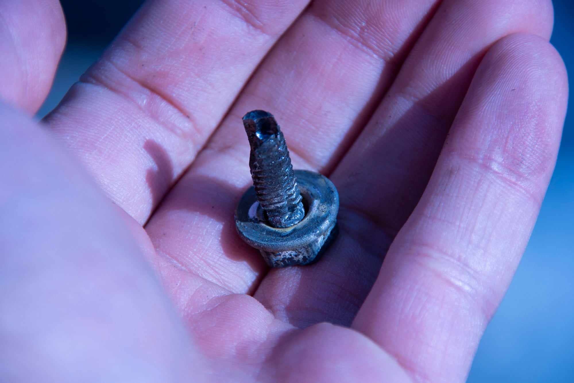
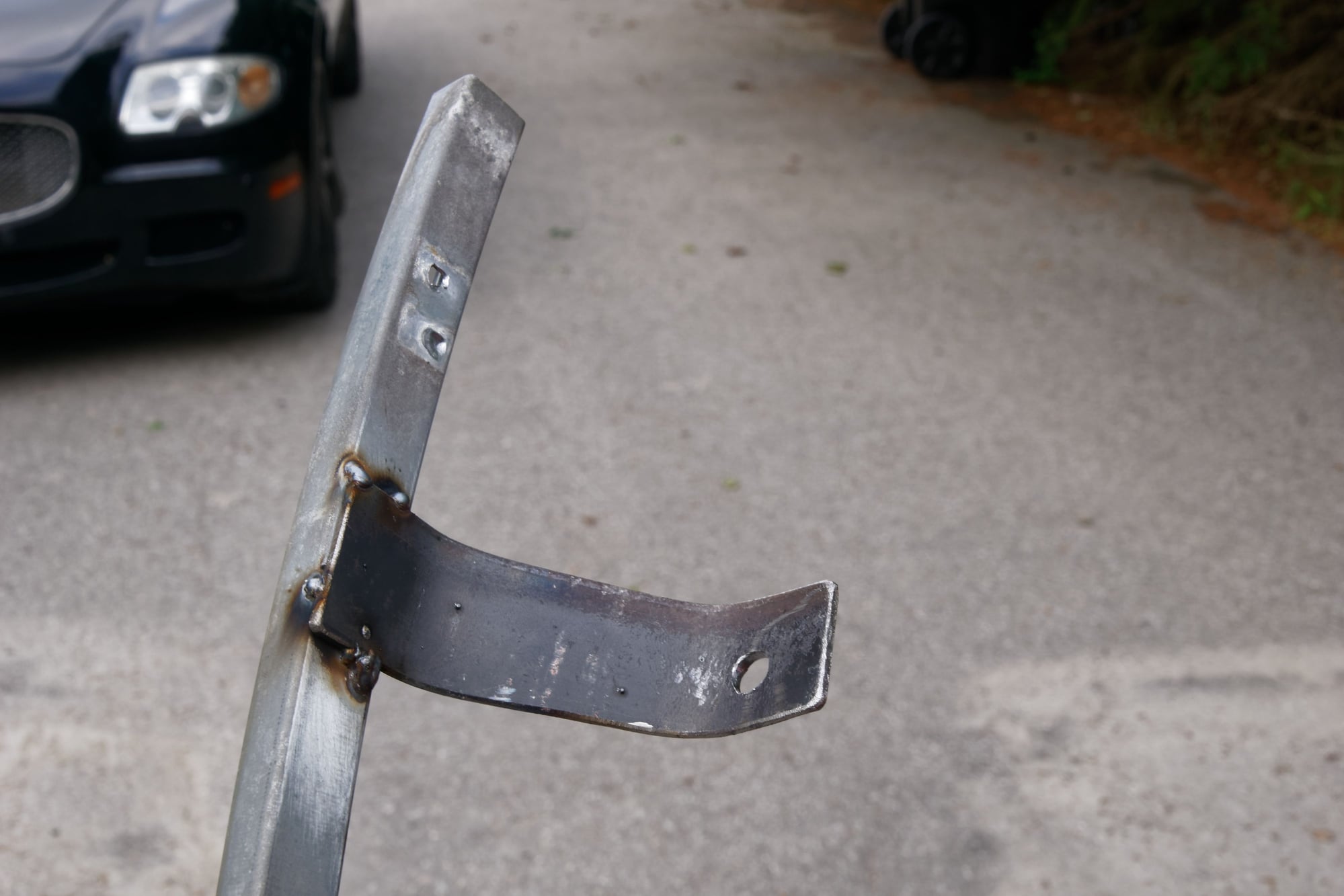
As you can tell there was not a lot of meat left on the mounting ear after this. So I cleaned everything with brake cleaner a few times and decided to fill it with JB Weld (bear with me, it’s not as crazy as it sounds):
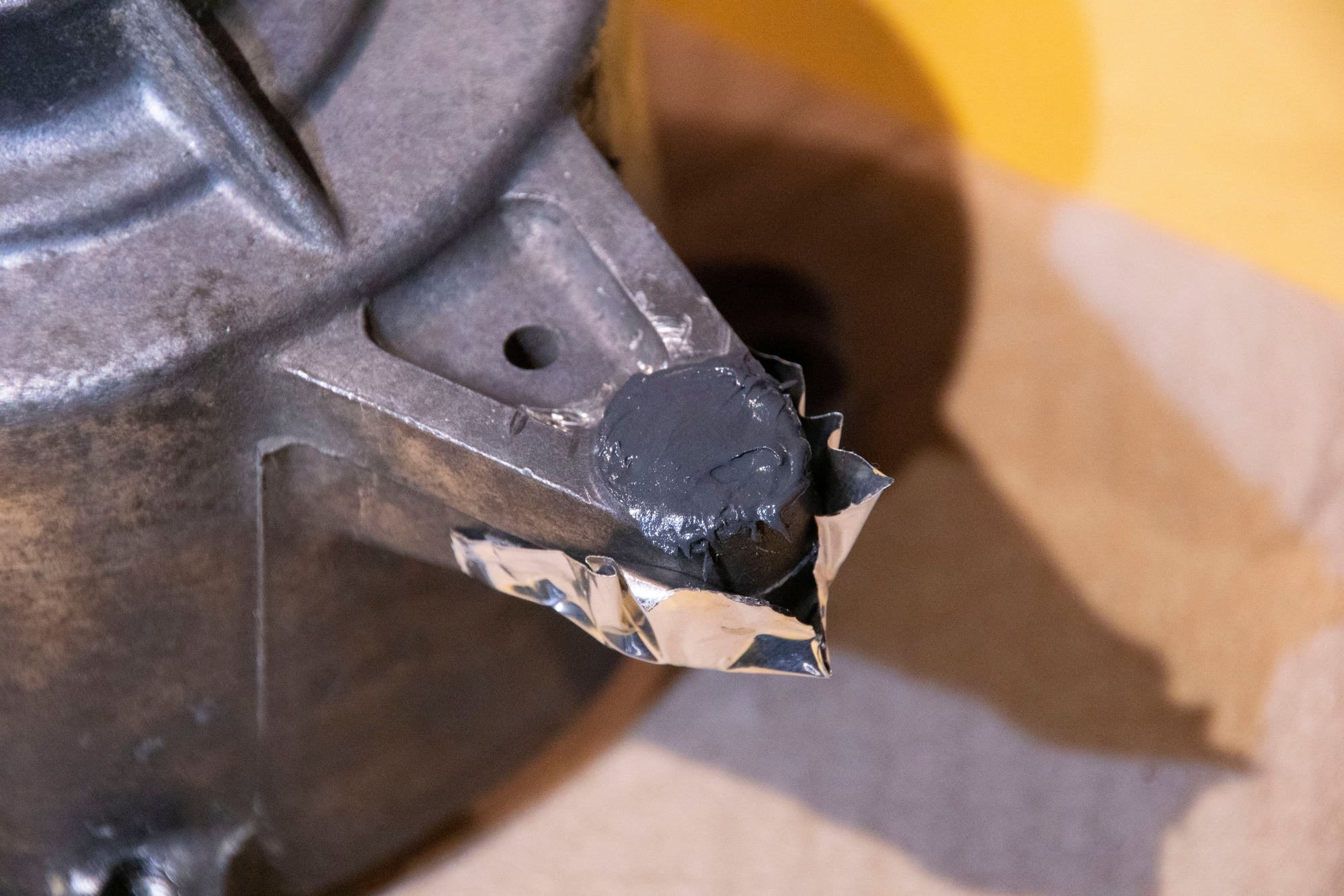
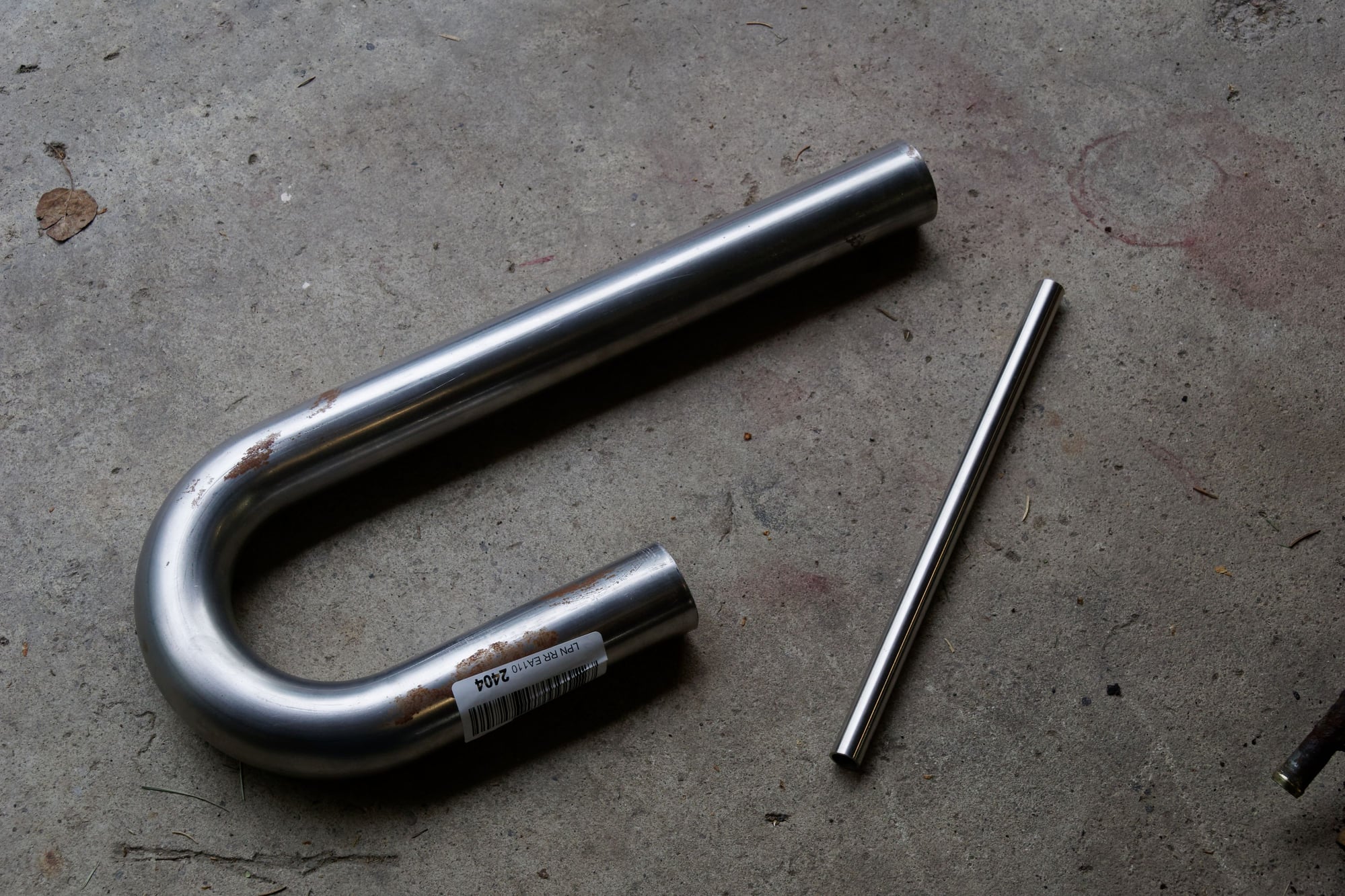
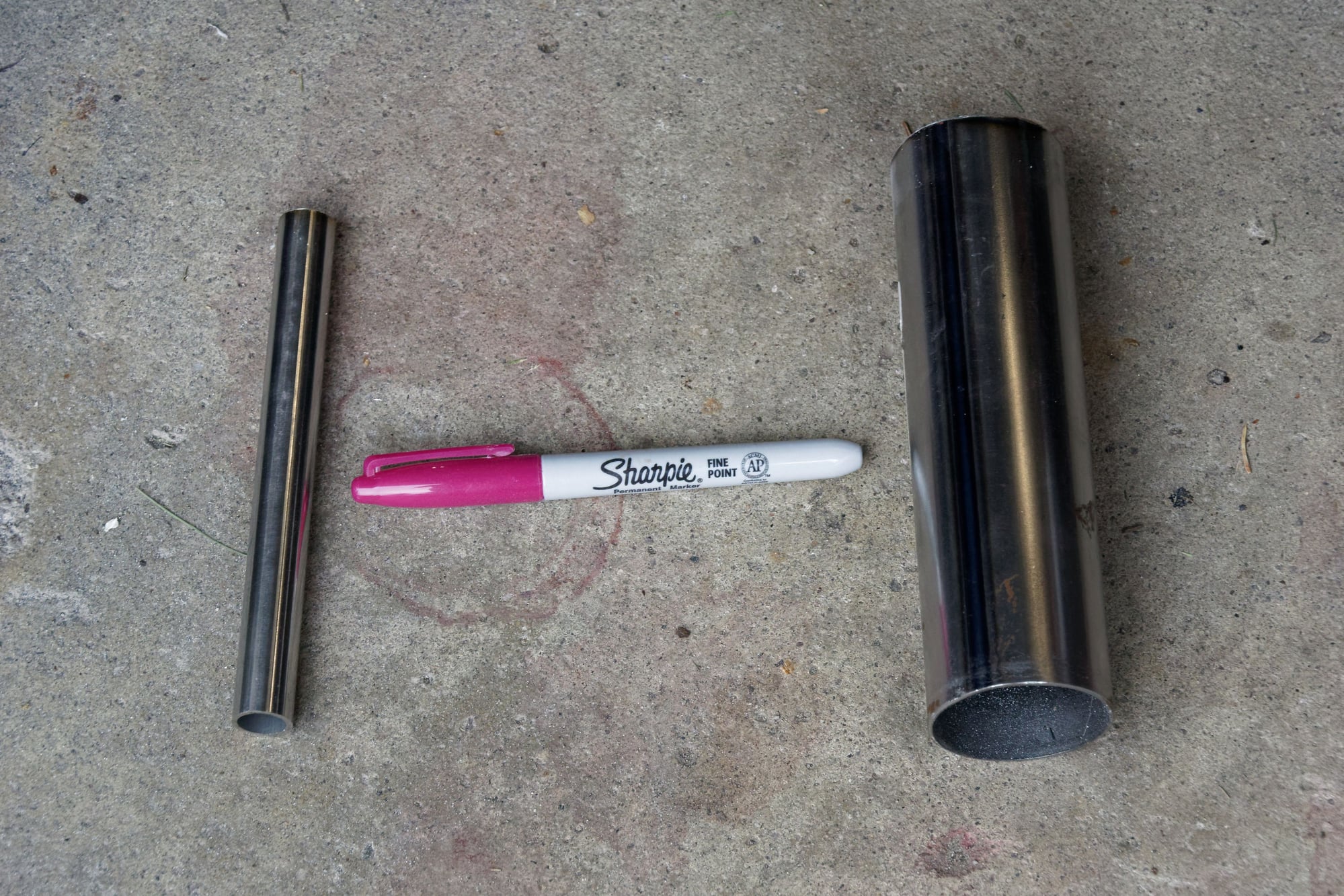
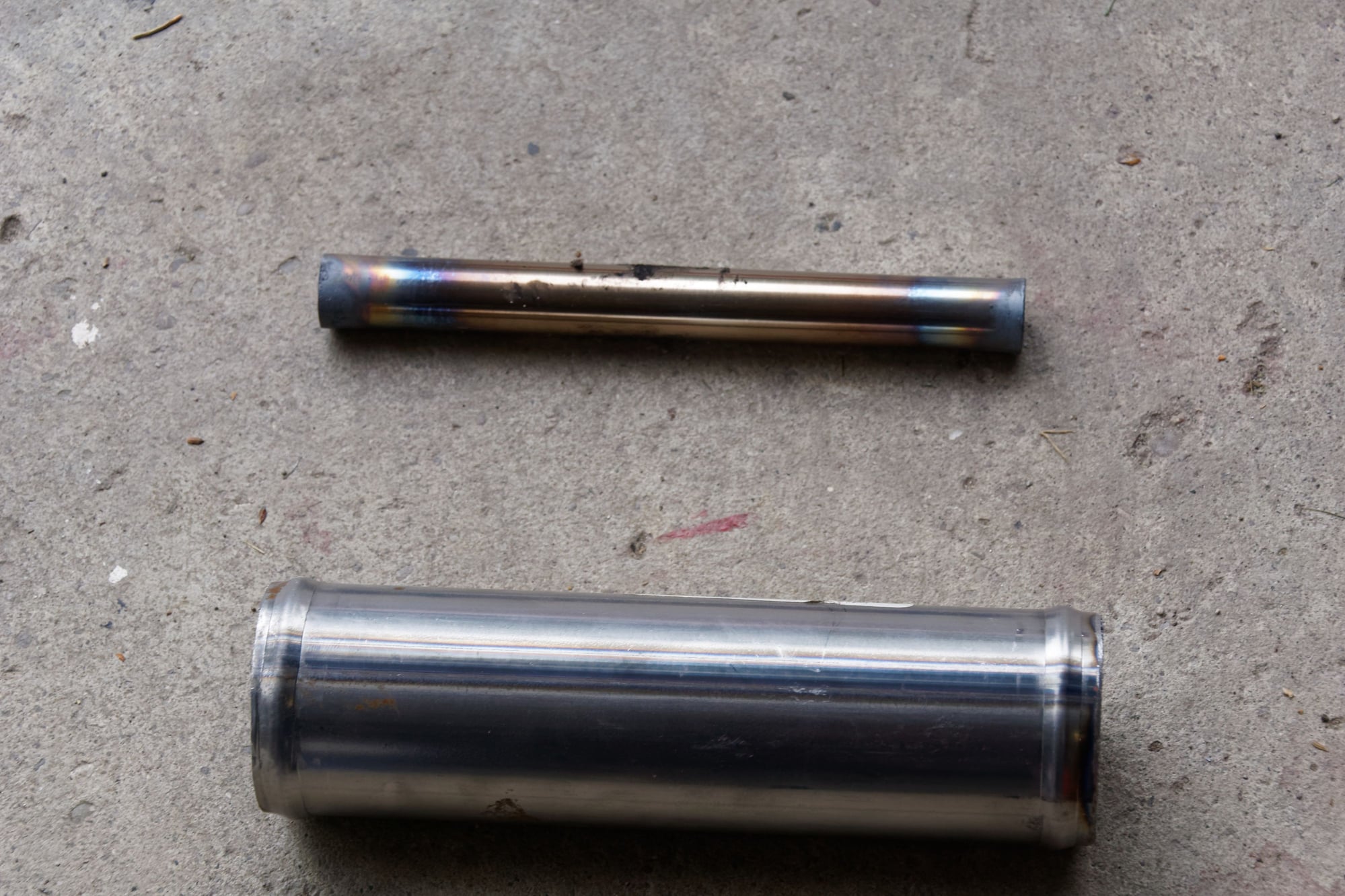
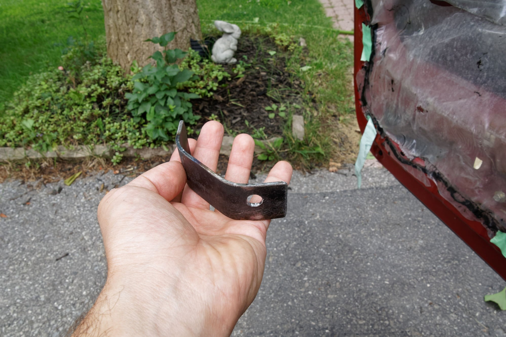
The epoxy won’t actually be taking much stress, because I’m going to use this steel insert:
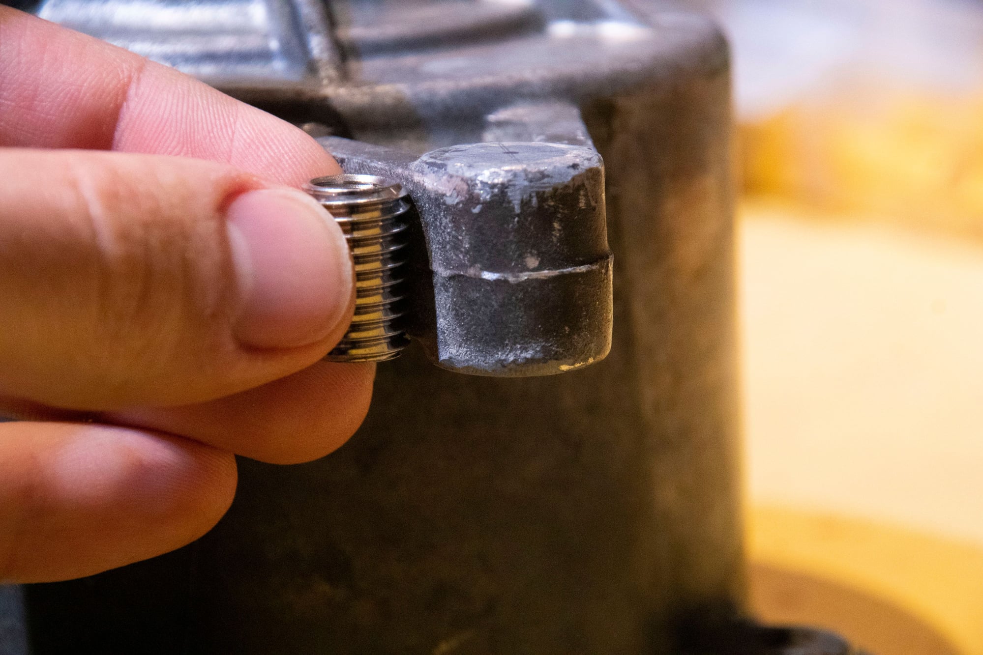
M12x1.75 outer, M8x1.25 inner.
You might ask whether it would be smarter to just use an unthreaded hole with a nut on the back, and the answer is “probably”. But I don’t like that solution because you need three hands to tension the belt with it. So I was determined to add threads back in for OEM functionality. Down to the correct M8x1.25 thread pitch.
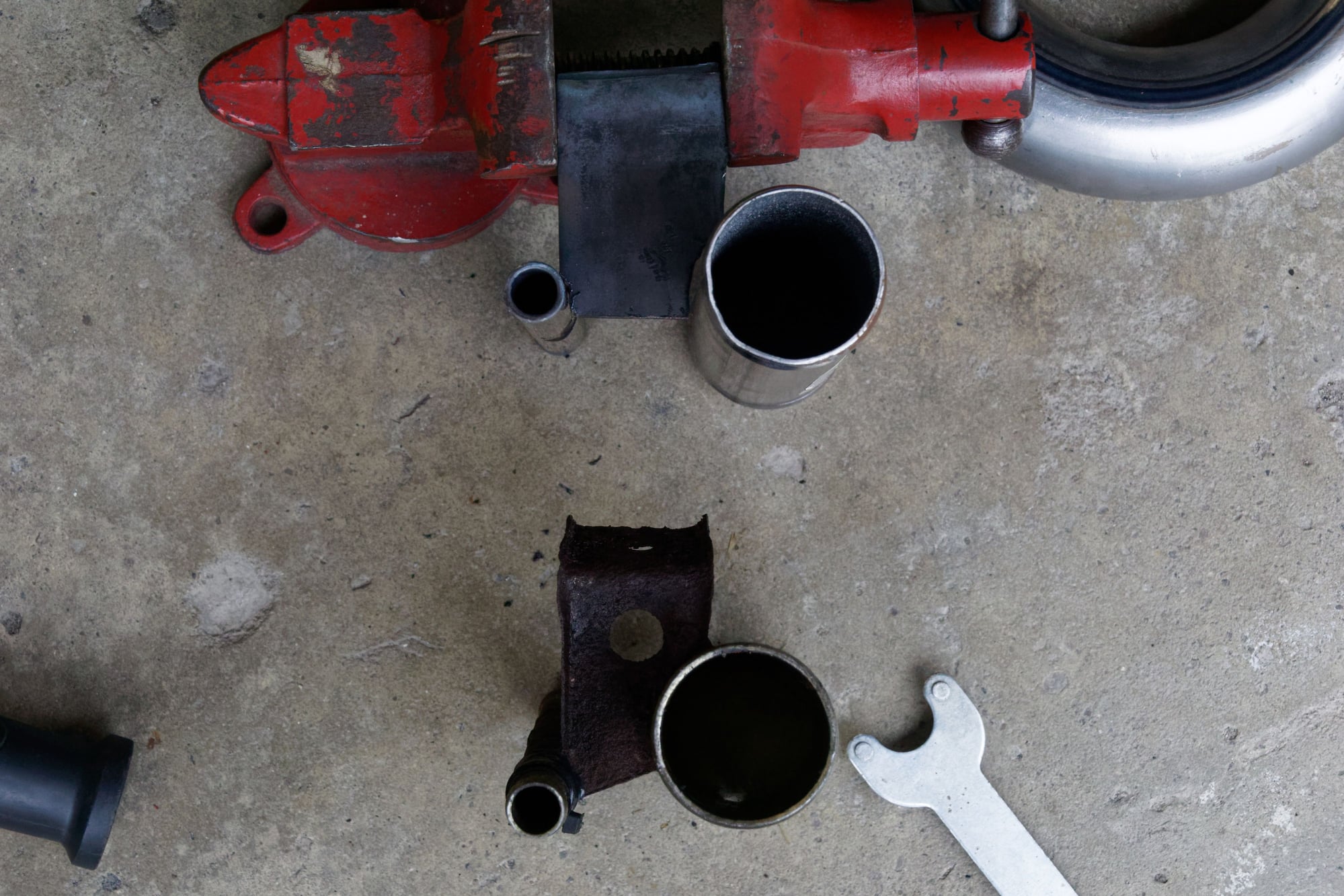
I drilled out the mounting ear to 11mm through, and then tapped it to M12x1.75 most of the way:
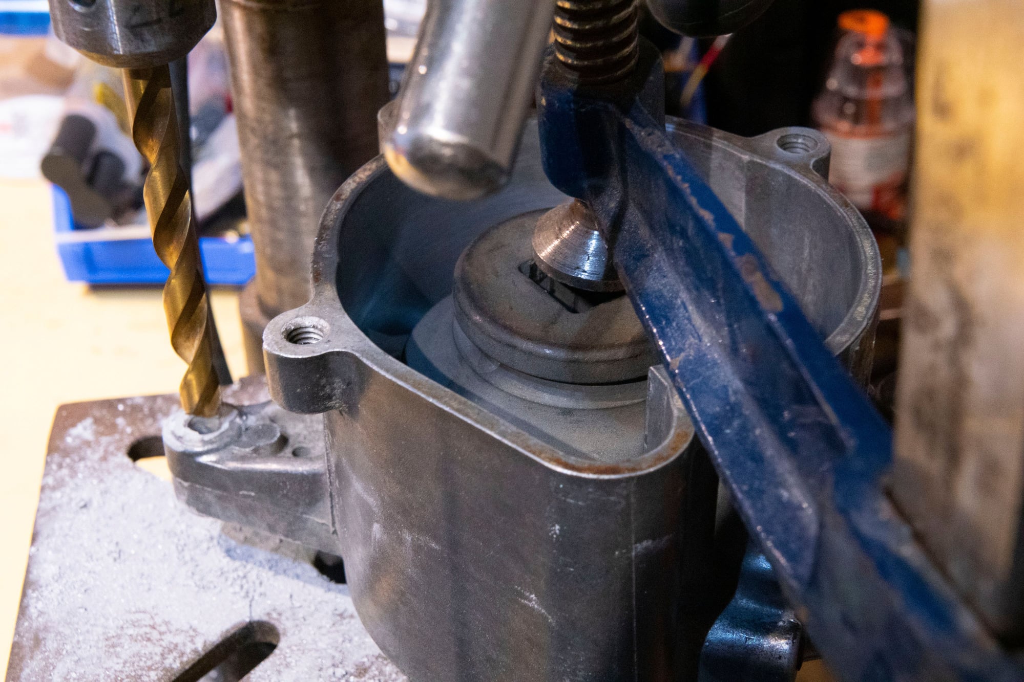
I've officially used the 54mm flywheel socket for clamping / pressing more often than I've actually used it on a flywheel
I didn’t tap it all the way because I wanted to insert the sleeve from the rear, so that the tightening action of the fastener pulls the insert forward and there is a bit of a ridge to help retain it without adding stress to the threads.
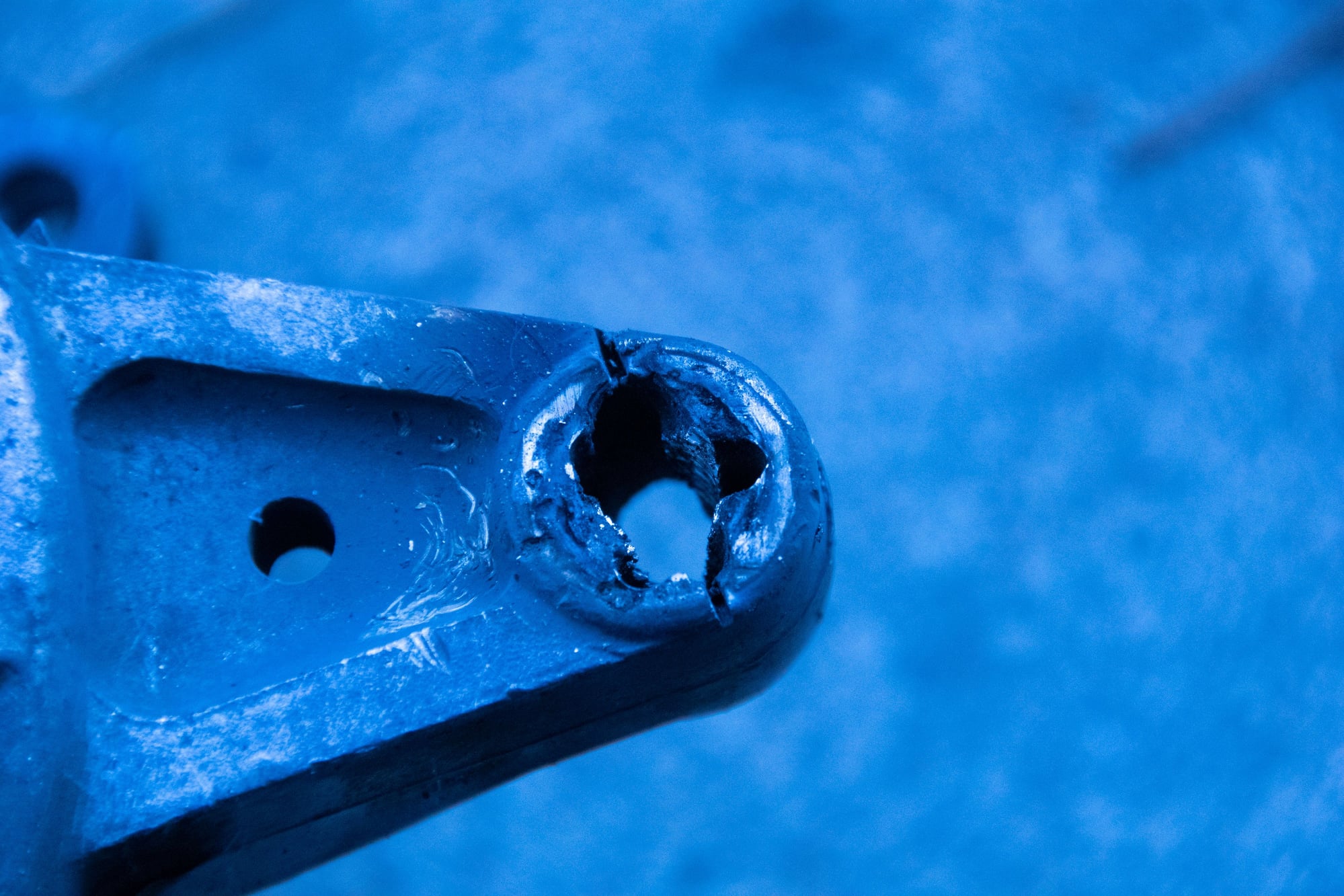
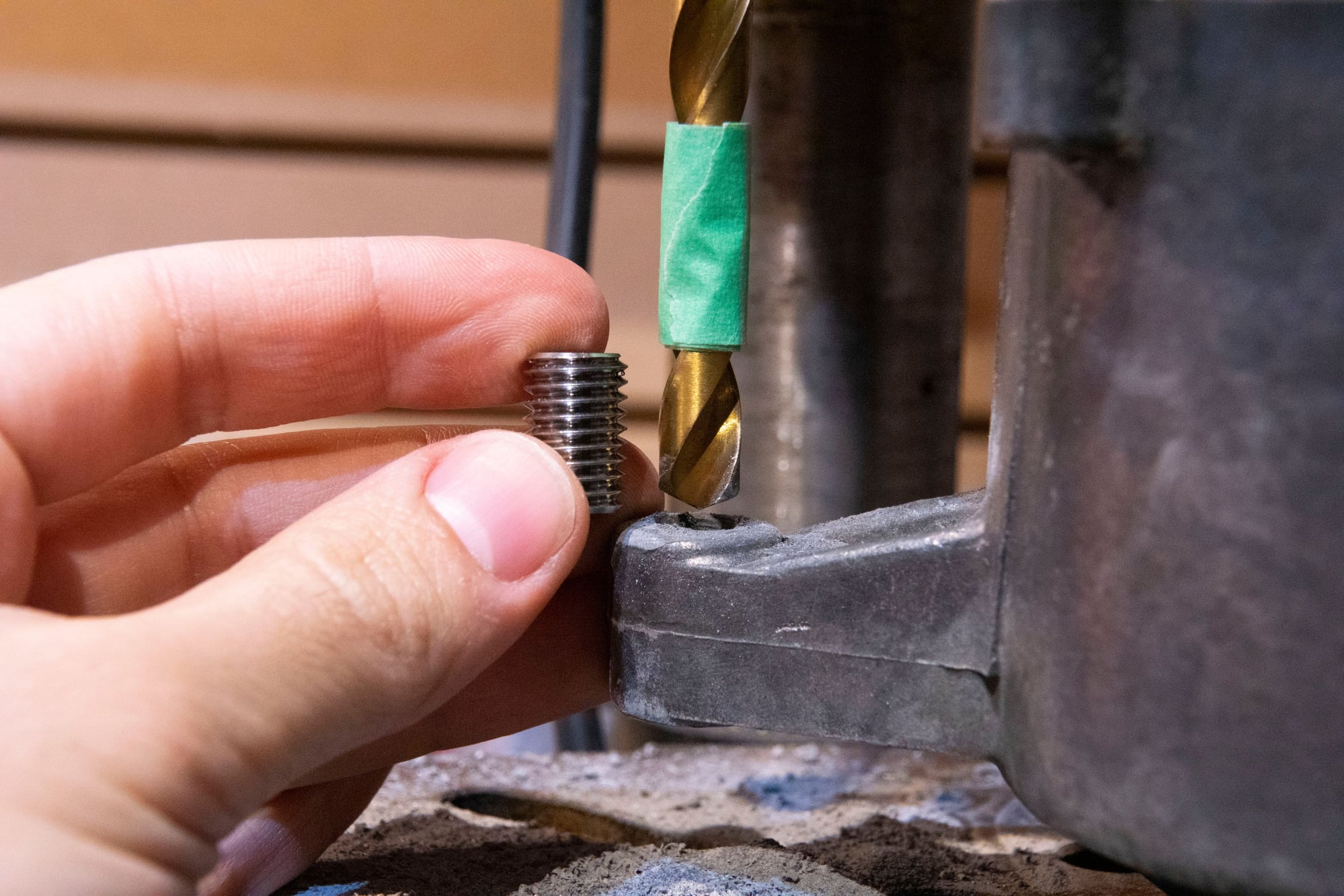
Speaking of the threads:
You can see what I meant with the JB Weld. It’s only filling some of the smaller voids where there was damage from the drill bit, and most of the threads are still aluminum.
Then I coated the inner threads with more JB Weld, threaded in the insert, tightened it, and used a bit of JB on the back side to help retain it.
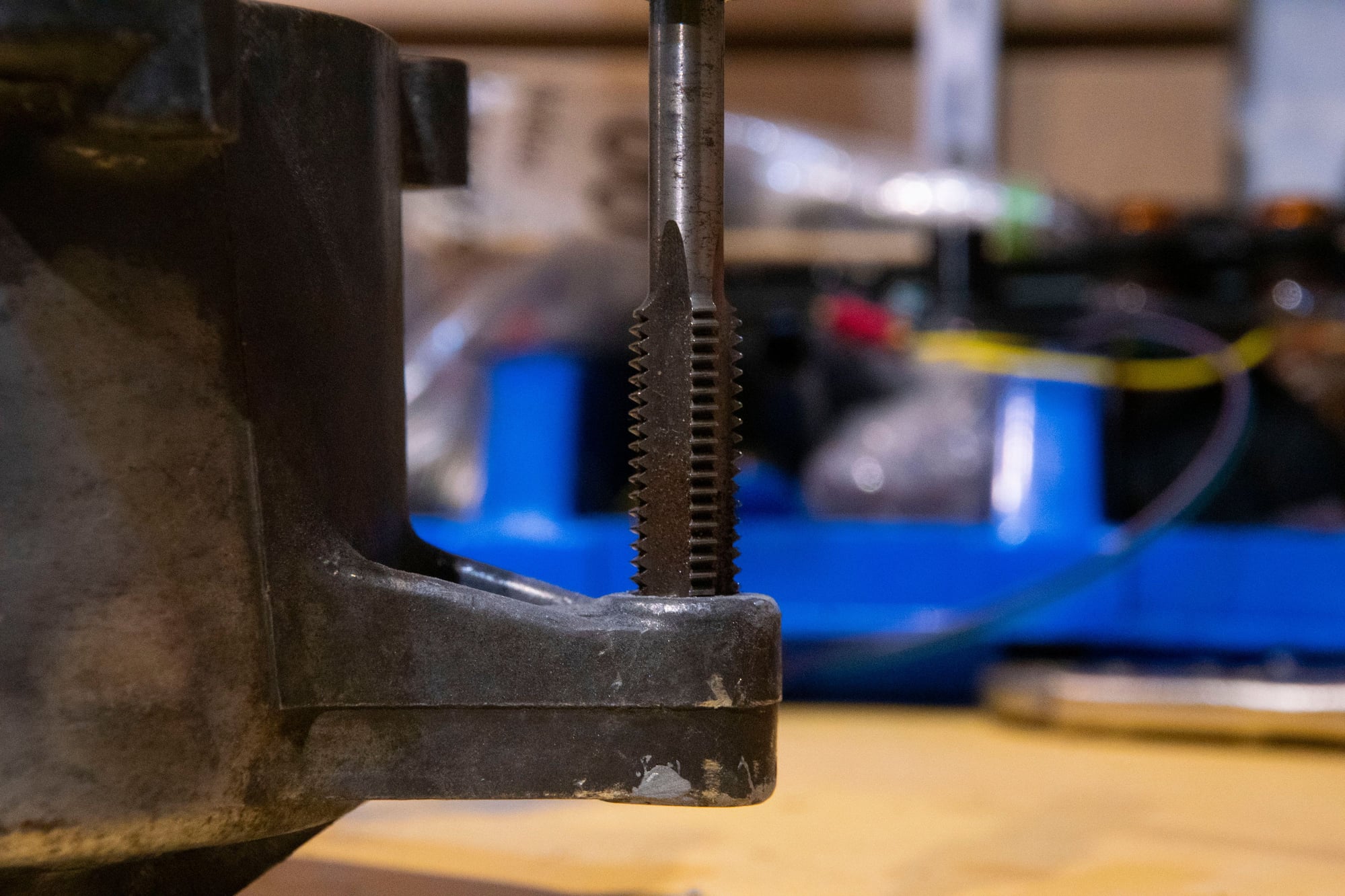
After running an M8 tap quickly through the insert to clear any epoxy that found it’s way in:
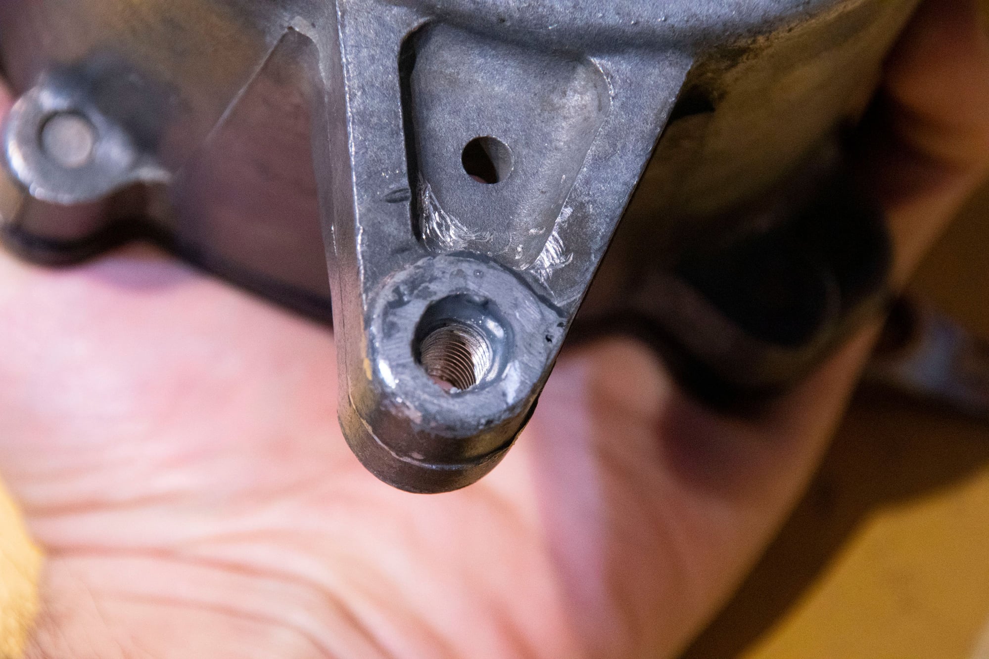
Nice clean threads. I’m confident this repair is going to be sturdy and long-lasting, and the problem is unlikely to reoccur since it’s now a steel fastener threading into steel threads. No galvanic reaction here. Plus I am compulsive about anti-seize.
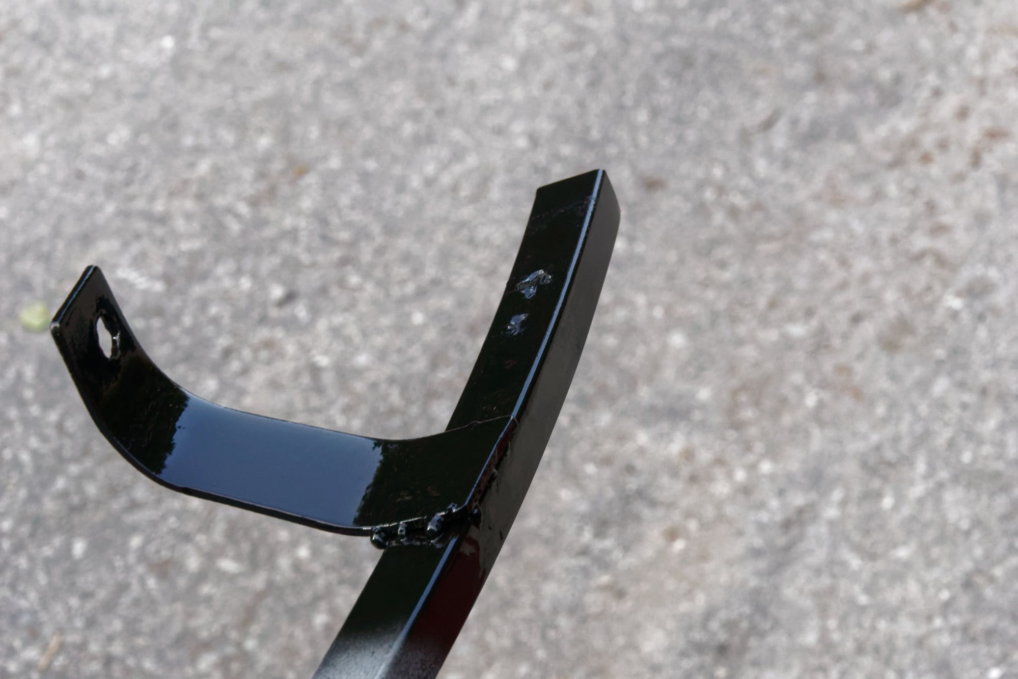
After that the inside of the housing, the rotor, and the back plate all got a good cleaning to remove the soot. I painted the back plate, pulley, and tensioner arm. I also lightly sanded the back plate and the inside of the housing where the vanes contact. Photos to come later.
Reassembly of the pump is the reverse of removal, but reinstalling the rotating assembly was a bit of a chore. Nothing crazy, and I forgot to photograph it, but I’ll explain.
The first 6204 bearing I tried installing in the housing was damaged because it required too much force and I foolishly used the wrong side of a socket to tap it in. Fortunately I purchased a set of two, so I put the second one in the freezer for an hour before reinstalling. Meanwhile I heated up the housing for an hour as well to expand it:
That copper ring inside is a sort of clutch. Together with the bearing I guess it qualifies as a viscous clutch? The outside of the bearing doesn’t really contact the housing, it contacts that copper ring and the ring contacts the housing. At idle and low rpm it behaves like a normal bearing, but then above 3000rpm the copper ring starts to spin in the housing (presumably due to the viscosity of the grease inside the bearing).
At least I think that’s how it works.
With the shrunk bearing and expanded housing, I was able to tap it home. Then I reinstalled the circlip.
After that I had to put the rotor in the freezer for an hour to shrink it and heat the housing + bearing back up to expand them, and then I tapped the rotor from the back side of the housing inward to seat it in the bearing. It also has a little mylar plate and shim that go between it and the bearing, so I made sure to put those back in first.
Then I had to put the entire assembly in the freezer while I heated up the front hub, and tap the front hub home (being careful to put the flywheel socket under the rotor so I was not tapping it out of the bearing while doing so).
Altogether it was a bit time-consuming, but it all went back without fuss.
Then I started reassembling the seals and vanes, again, careful to put them back where they came from:
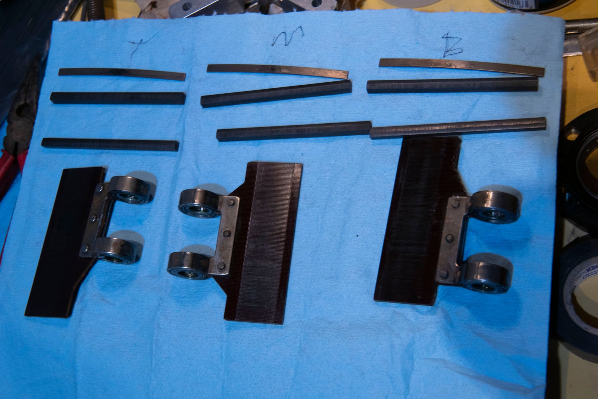
I had marked the alignment of the rotor and used a marker to remind myself where everything went. I first put the seals back in:
The seal that has a spring behind it sits in the deeper groove. For now I treated it like an apex seal and didn’t put the spring in yet. Then I put the vanes in:
Each of the vanes has two small bearings, so after cleaning them in the ultrasonic cleaner I thoroughly regreased them. I wasn’t sure exactly what grease was best so I went with silicone brake grease. I figured it has the high heat tolerance required, while also having enough staying power not to creep out of the bearings into the housing.
The bearings won’t stay concentric without the back plate, which is to come after the springs. I inserted the springs and pushed them all the way home. They make a tactile “click” when they are all the way home.
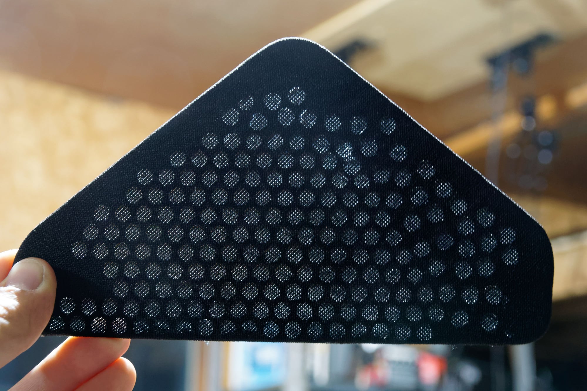
Then I pushed the vanes roughly into position. I managed to get this nice picture that shows the vane, the bore it sits in, and the nice fresh housing surface it seals against:
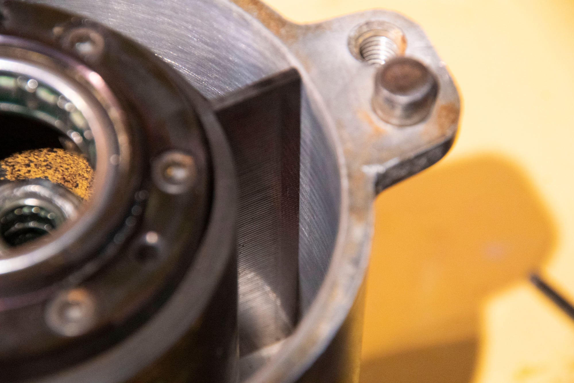
It didn’t take a lot of sanding. All I was doing was removing a bit of oxidation and whatever crap had stuck to the housing, but the surface itself was relatively unmarred.
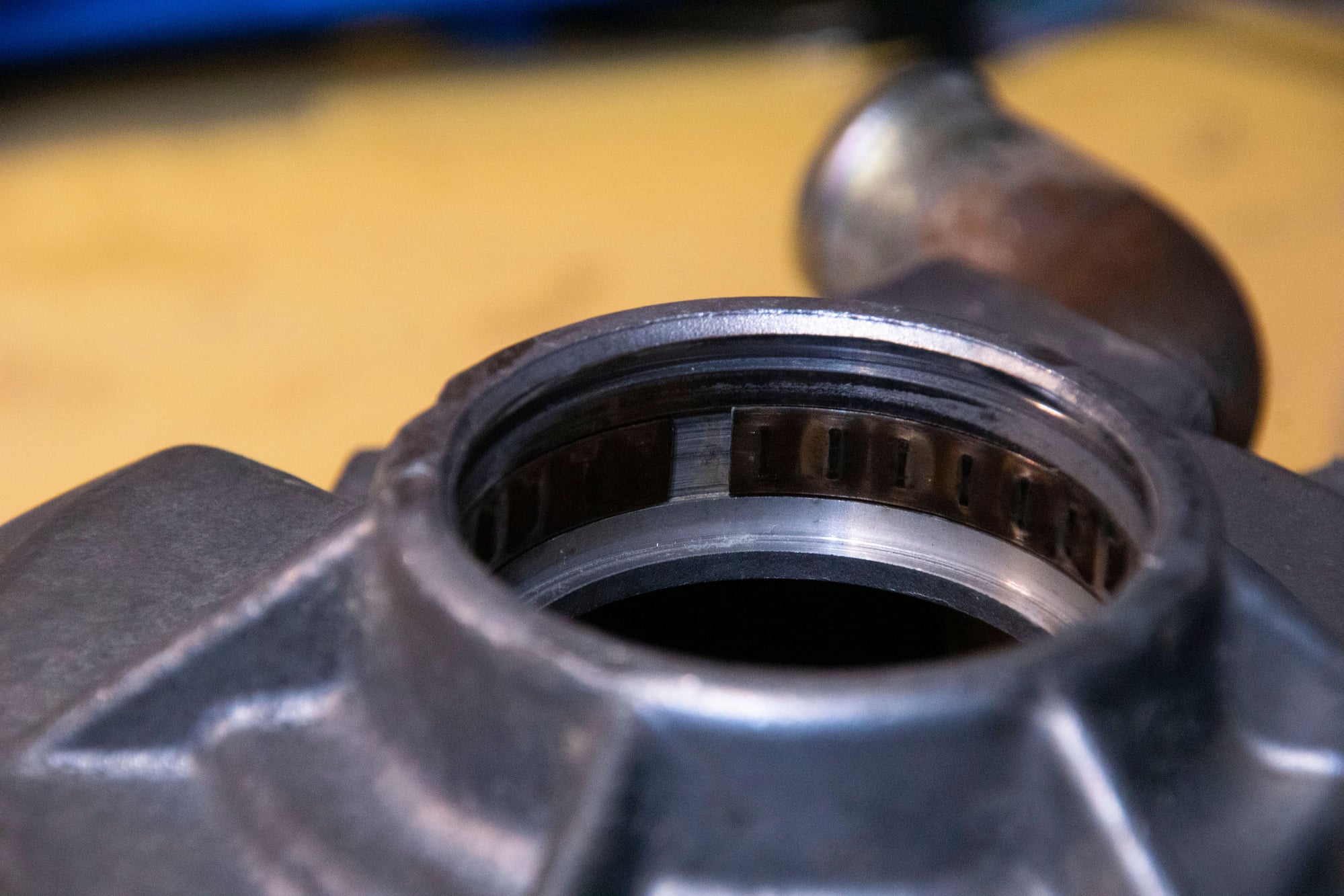
Then the rear bearing and retainer plate go on, again, careful to keep the alignment correct:
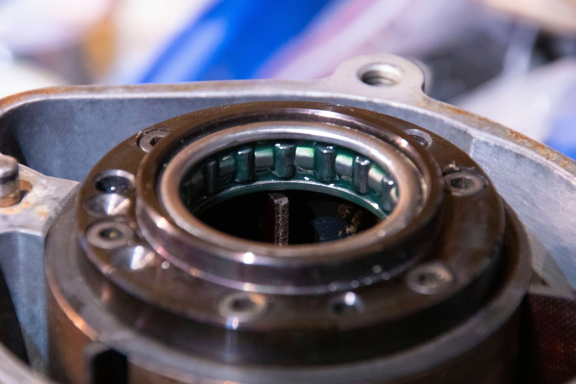
You can see the nice fresh grease in the bearing. I’m glad the bearing was still smooth, as I would not have been able to source a new one.
One thing to note is that there is some sort of babbit type material on that aluminum divider that separates the sides of the pump. Much of mine had flaked off, so I scraped away anything loose and then sanded it a bit to smooth it. I’m assuming this is there to reduce pressurized air slipping back to the inlet side and decreasing the pump’s efficiency, but I don’t have a good way of repairing it and the clearance is small as-is. I’m not worried about it.
With that the rear housing goes on. The shaft engages in the bearings for all of the vanes, so I had to fiddle with it a bit to get everything to align. But once it slides home, the bearings are concentric to one another. Then the bearing surface at the back of the rear plate engages in the rear bearing and it maintains the vanes at the correct eccentricity from the center of the pulley to keep everything in the right place.
Lastly I tightened down the 4 12mm bolts in an across pattern:
And reinstalled the pulley:
And there we go. One fully rebuilt air pump. Well, not fully, because I didn’t replace the vanes and have no idea how to measure their wear. But it now spins smoothly and absolutely moves air, so I’m calling it good.
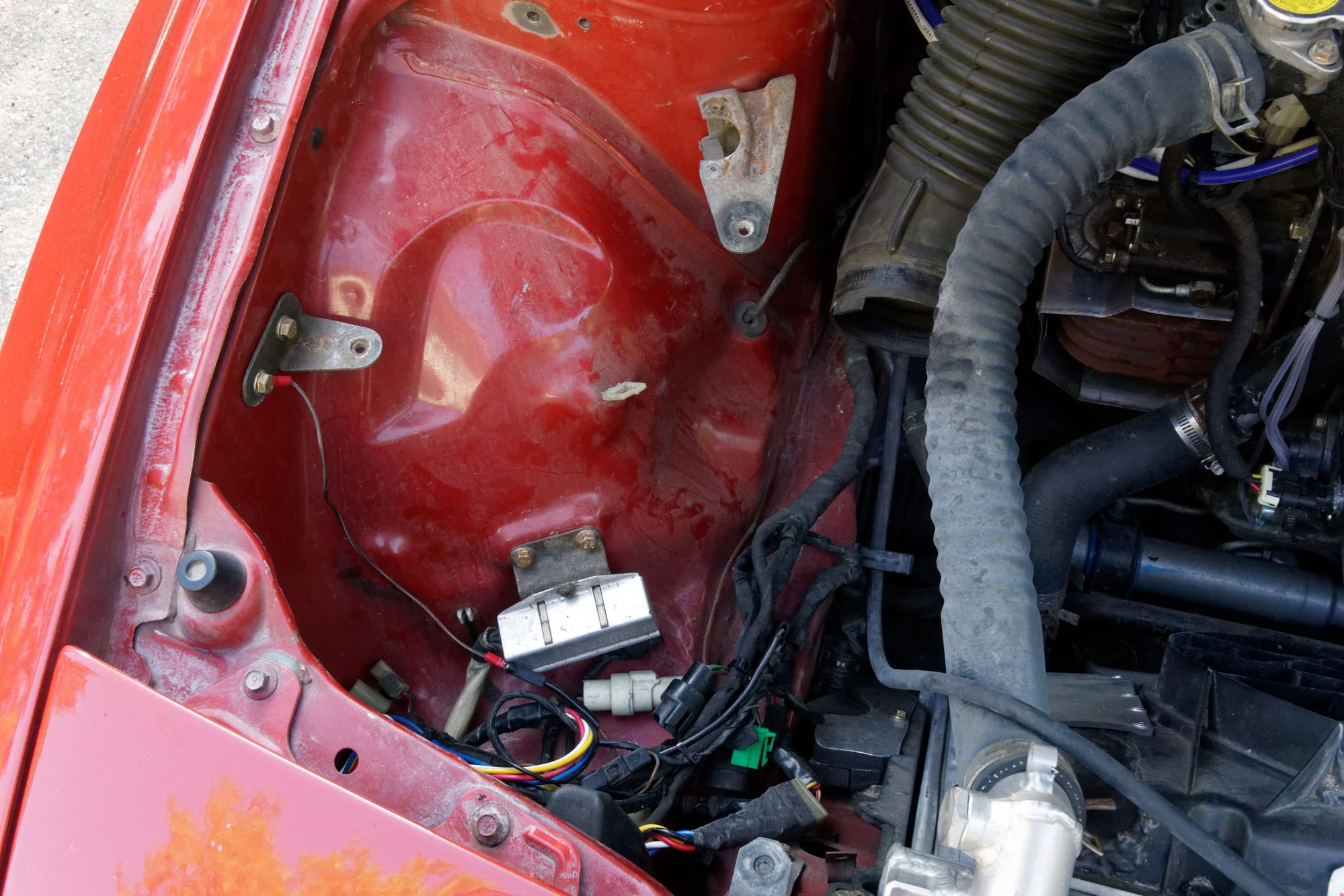
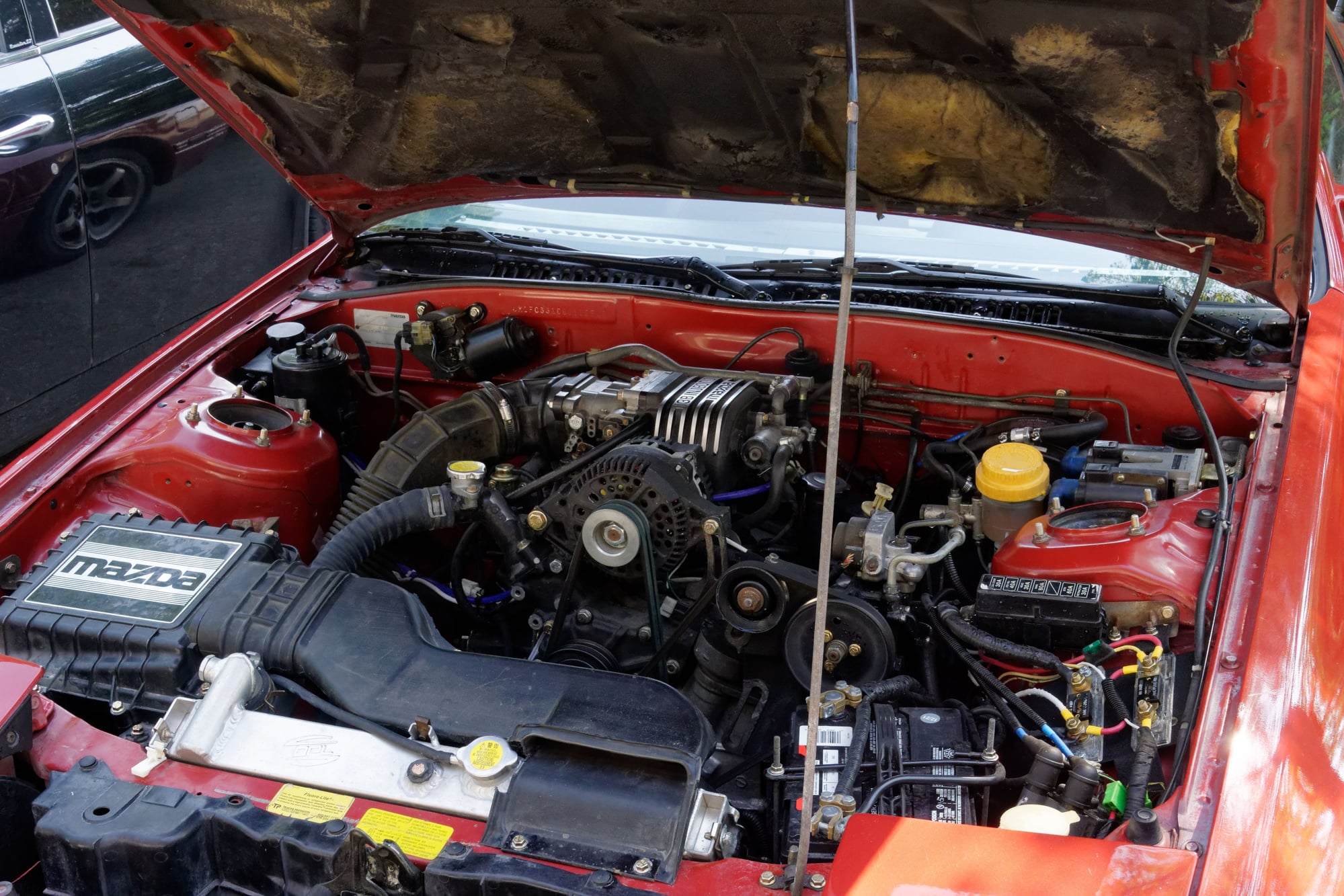
Did you guess the problem I mentioned earlier that makes the air pump difficult to use? That’s right, I put a crank sensor where the adjuster arm normally goes. At the time I was happy because my S10 crank sensor setup didn't interfere with any stock components, but I had forgotten about this one stock component... I could install the arm on top of the sensor mount but then the belt will want to occupy the same place as the sensor anyways, so I still have some thinking to do.
Probably a bit underwhelming since I doubt anyone cares about this part, but it lays the foundation for some more interesting work to come. And if nothing else, I learned something.
Until next time :)


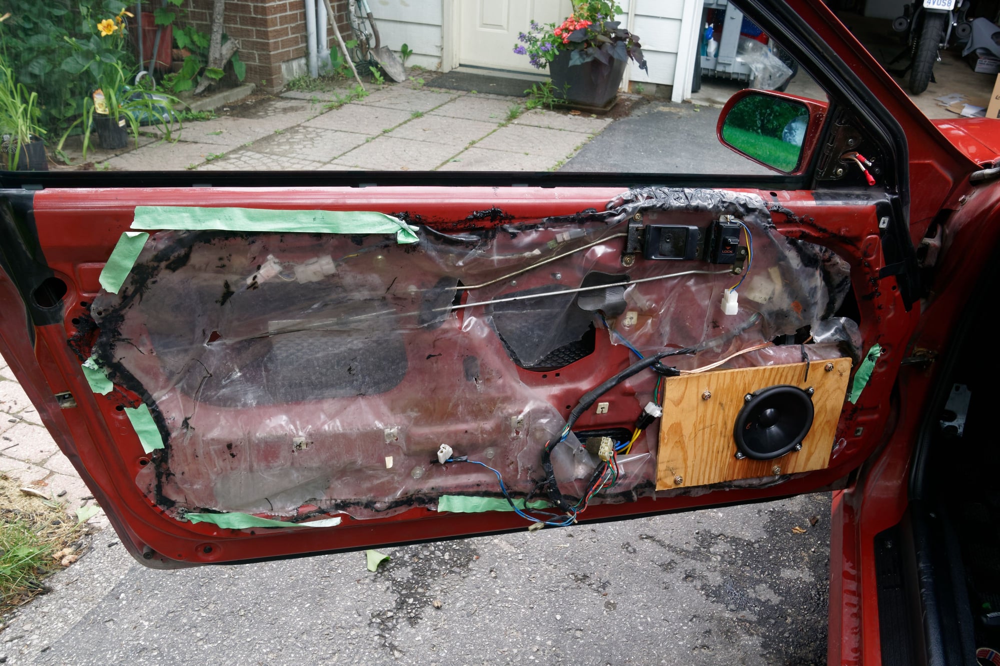
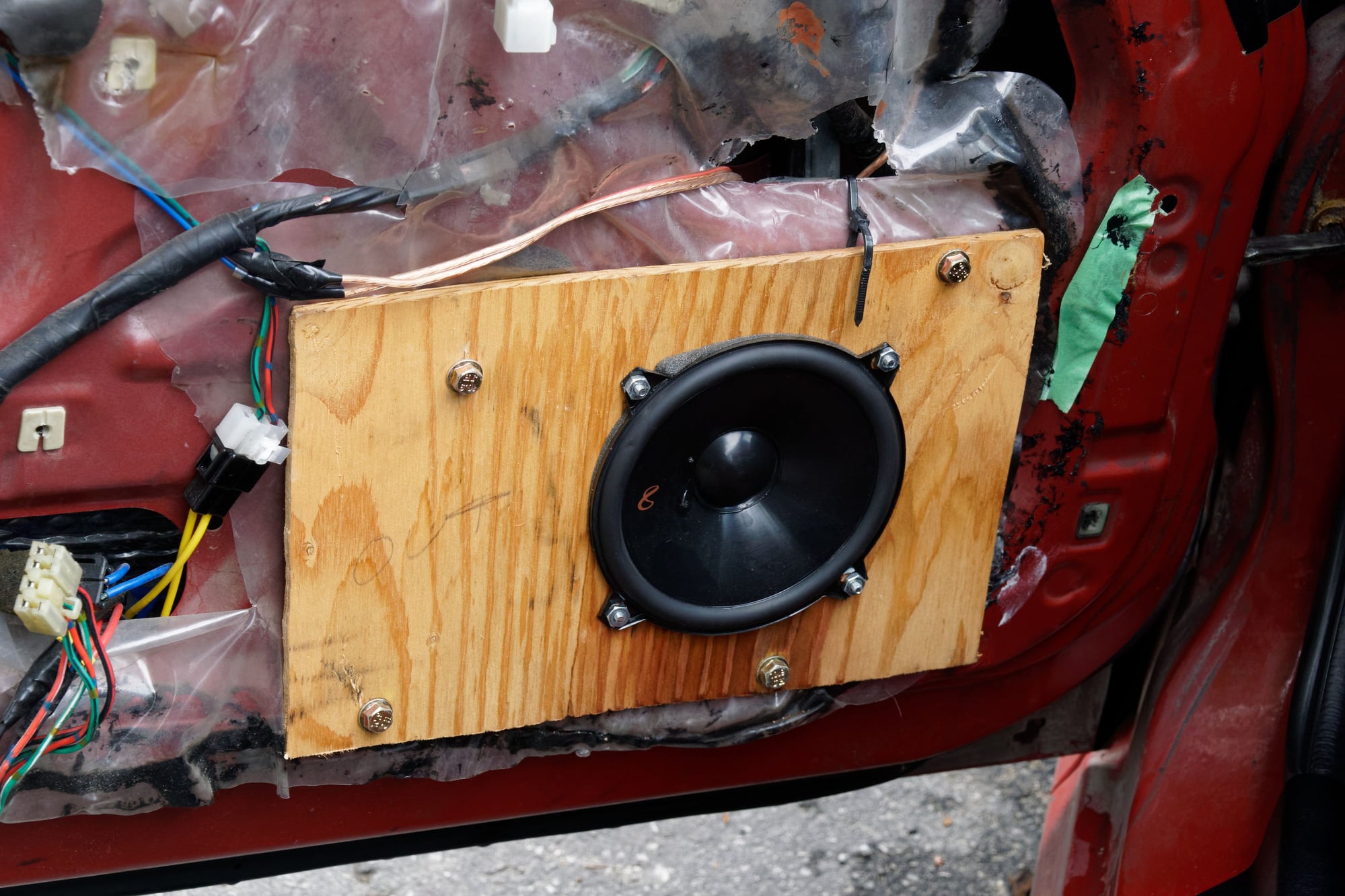
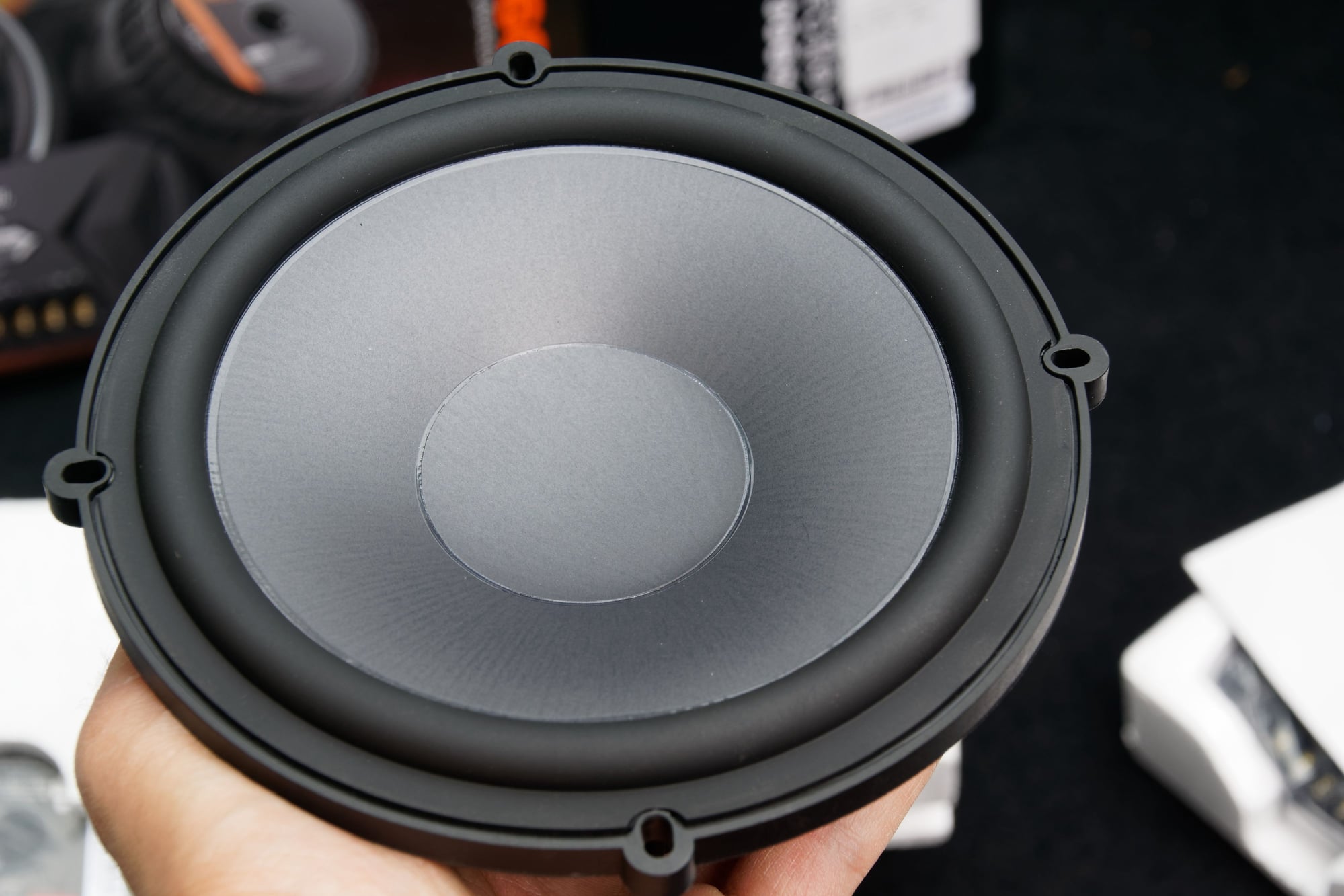
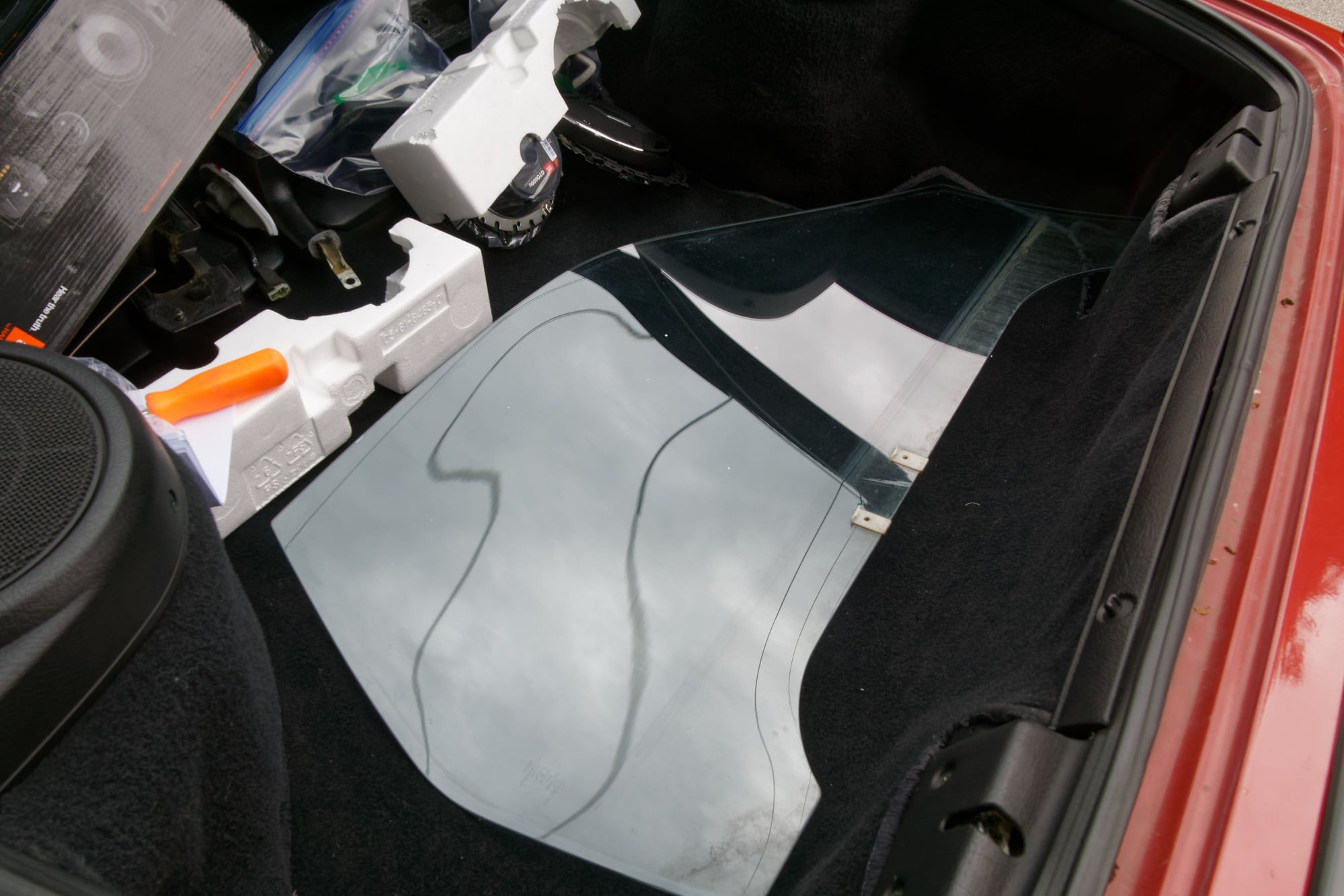
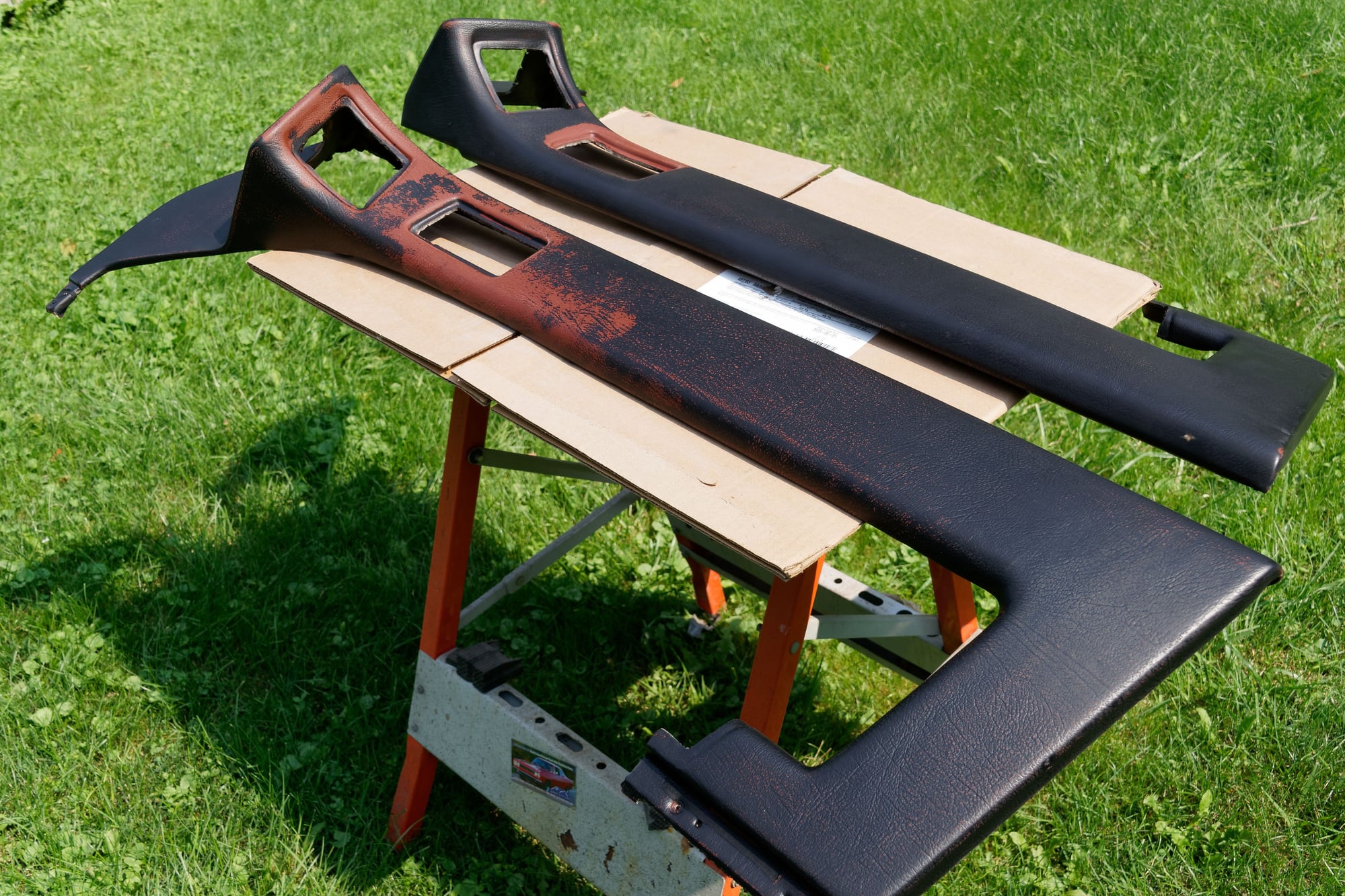
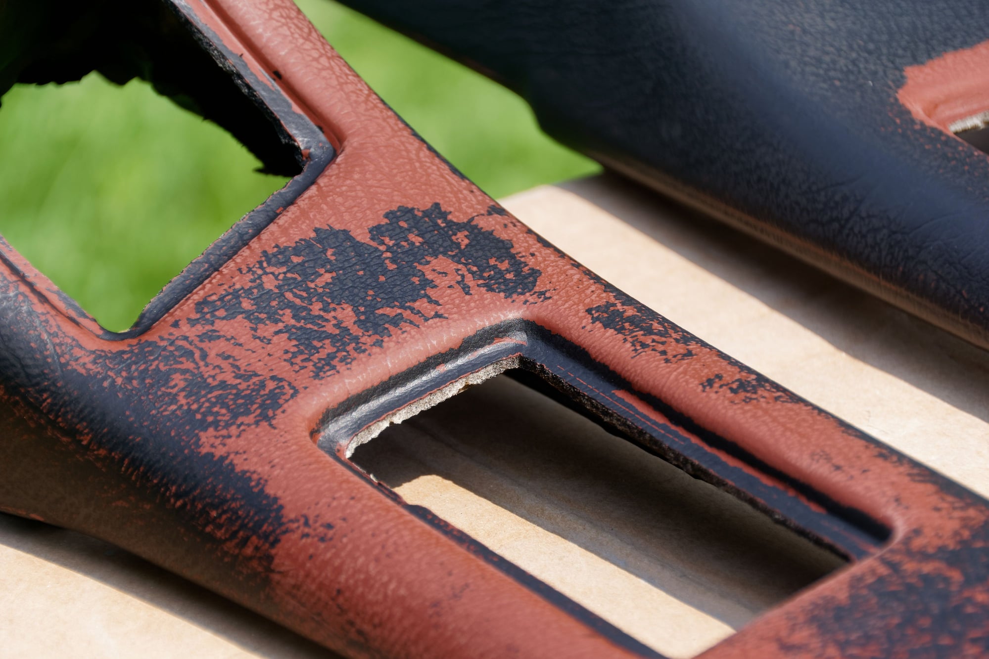
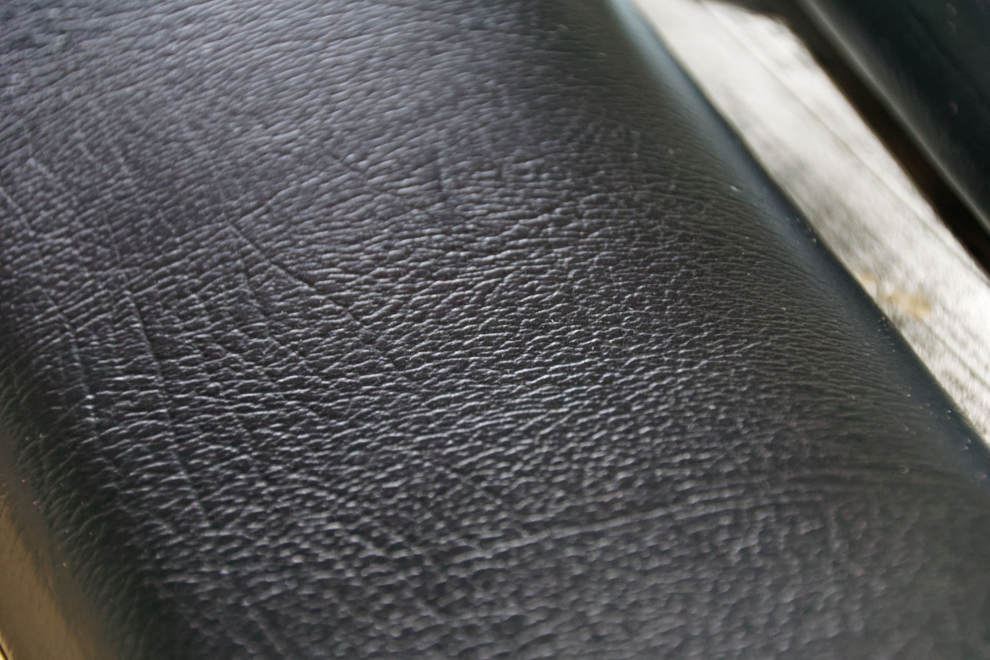
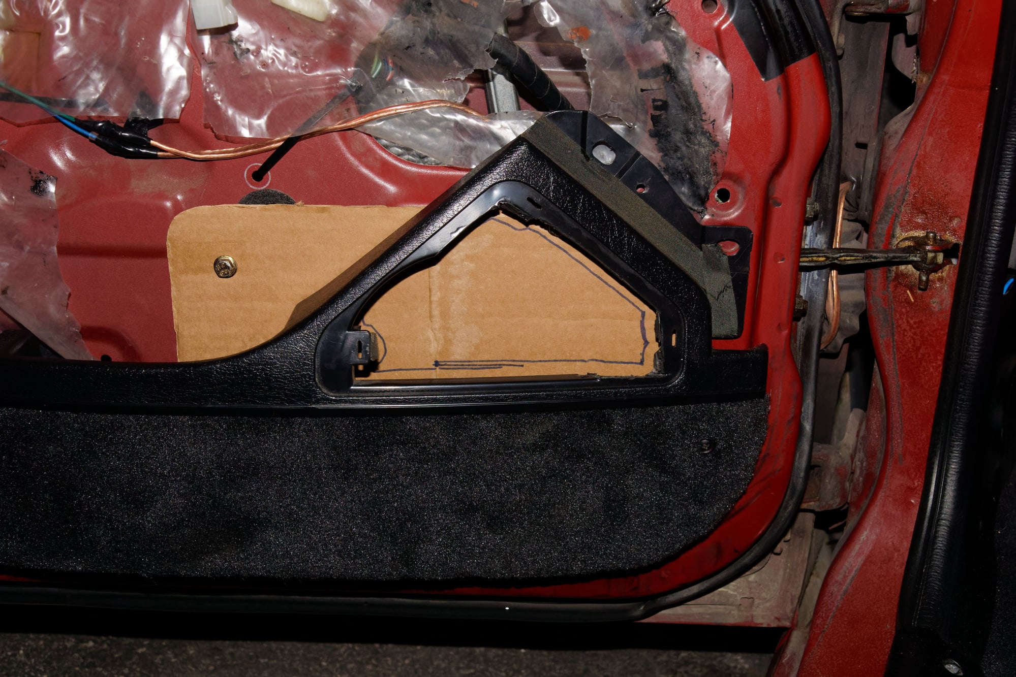
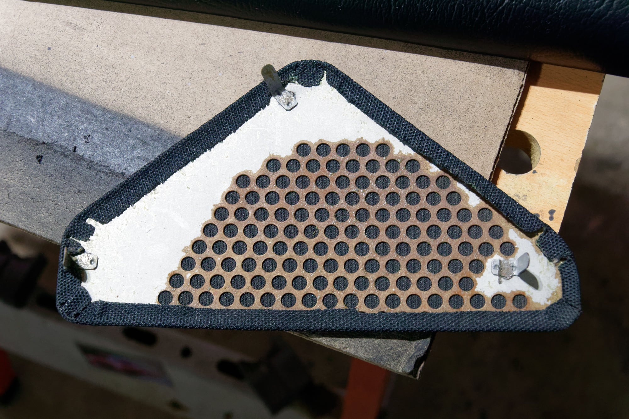
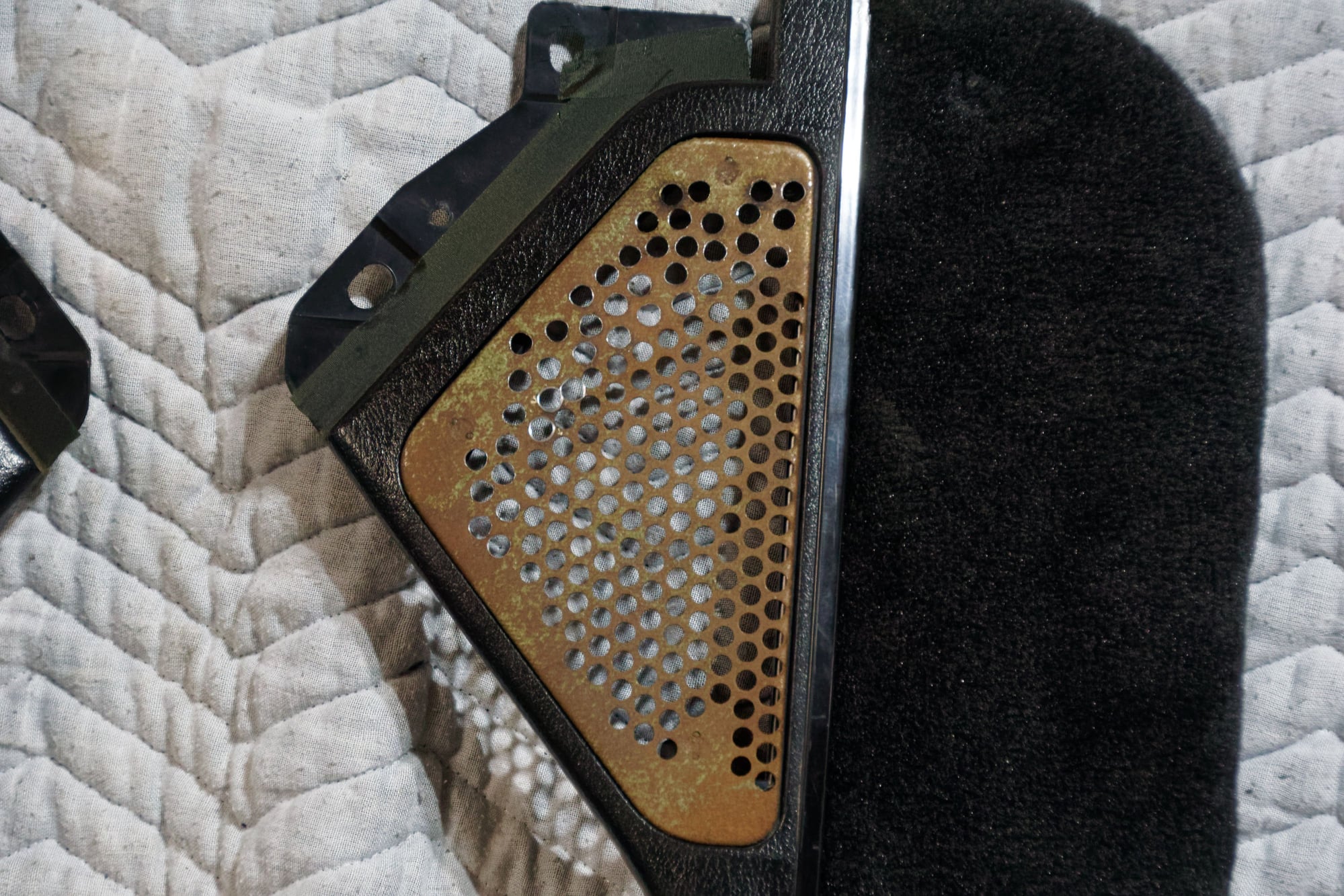
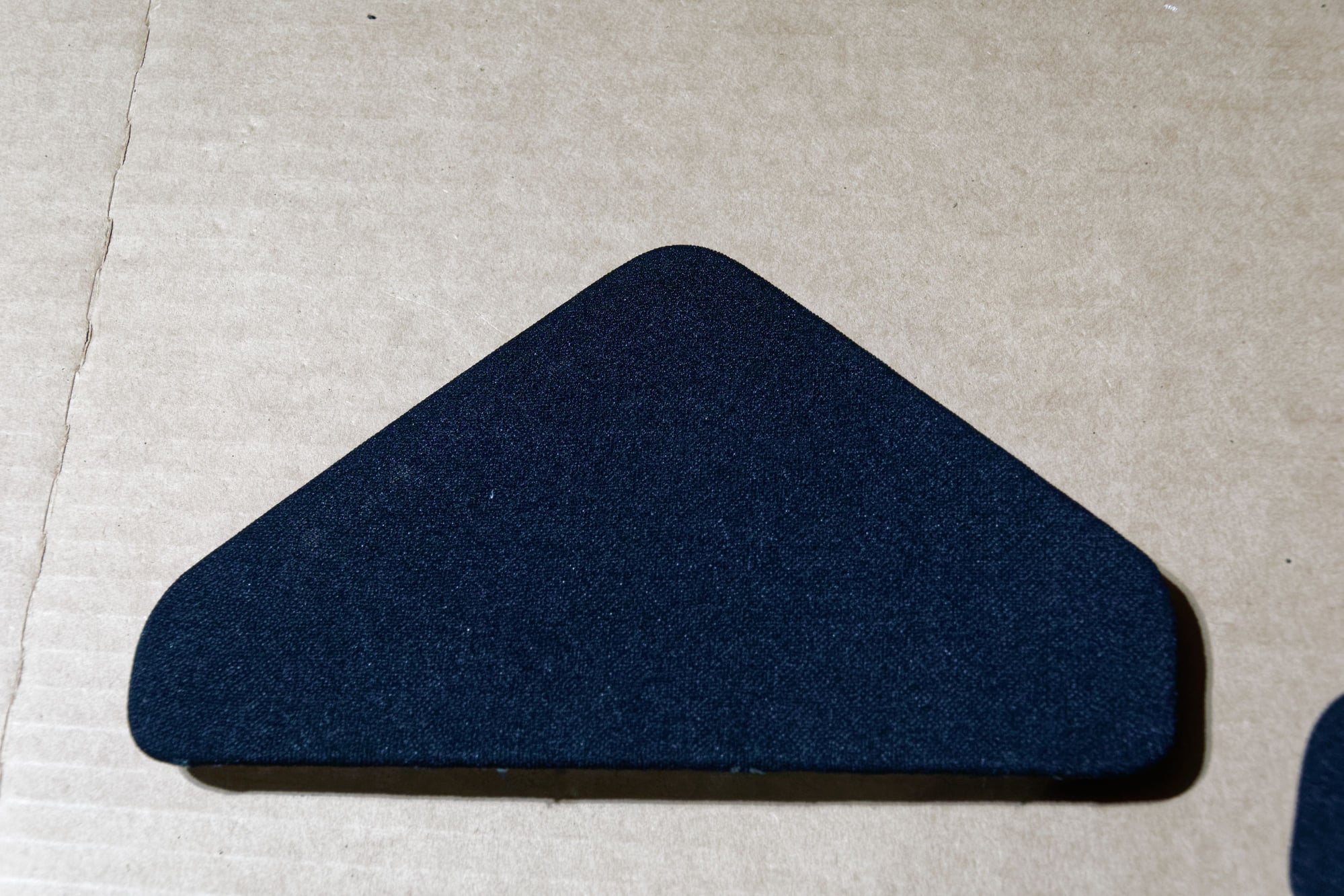
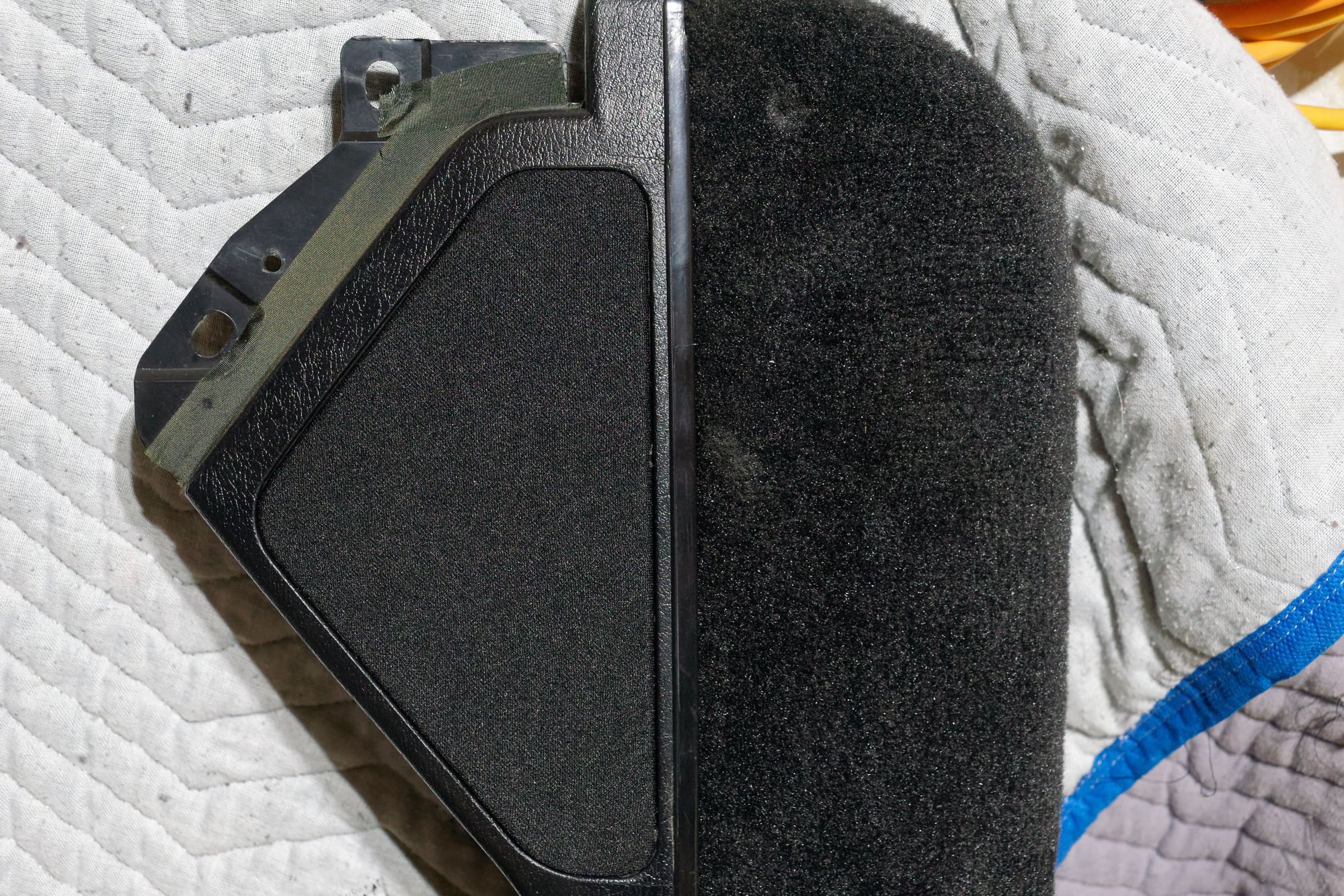
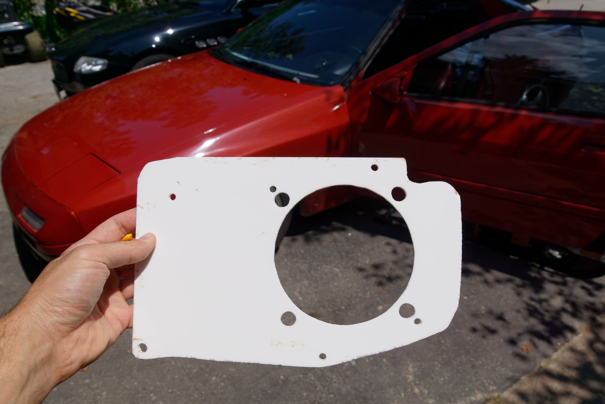
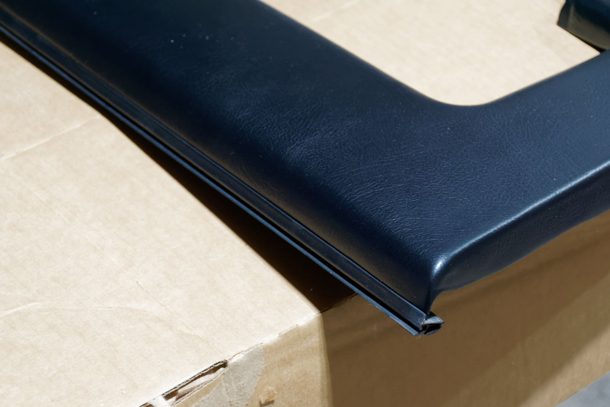
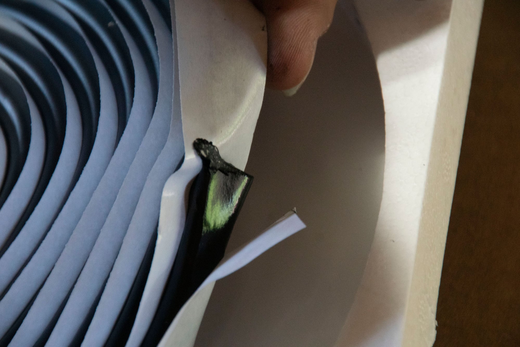
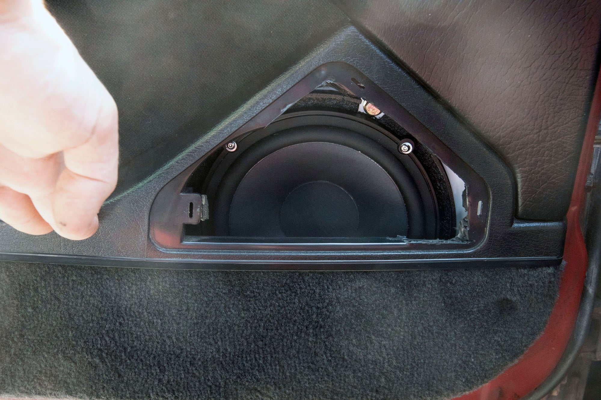
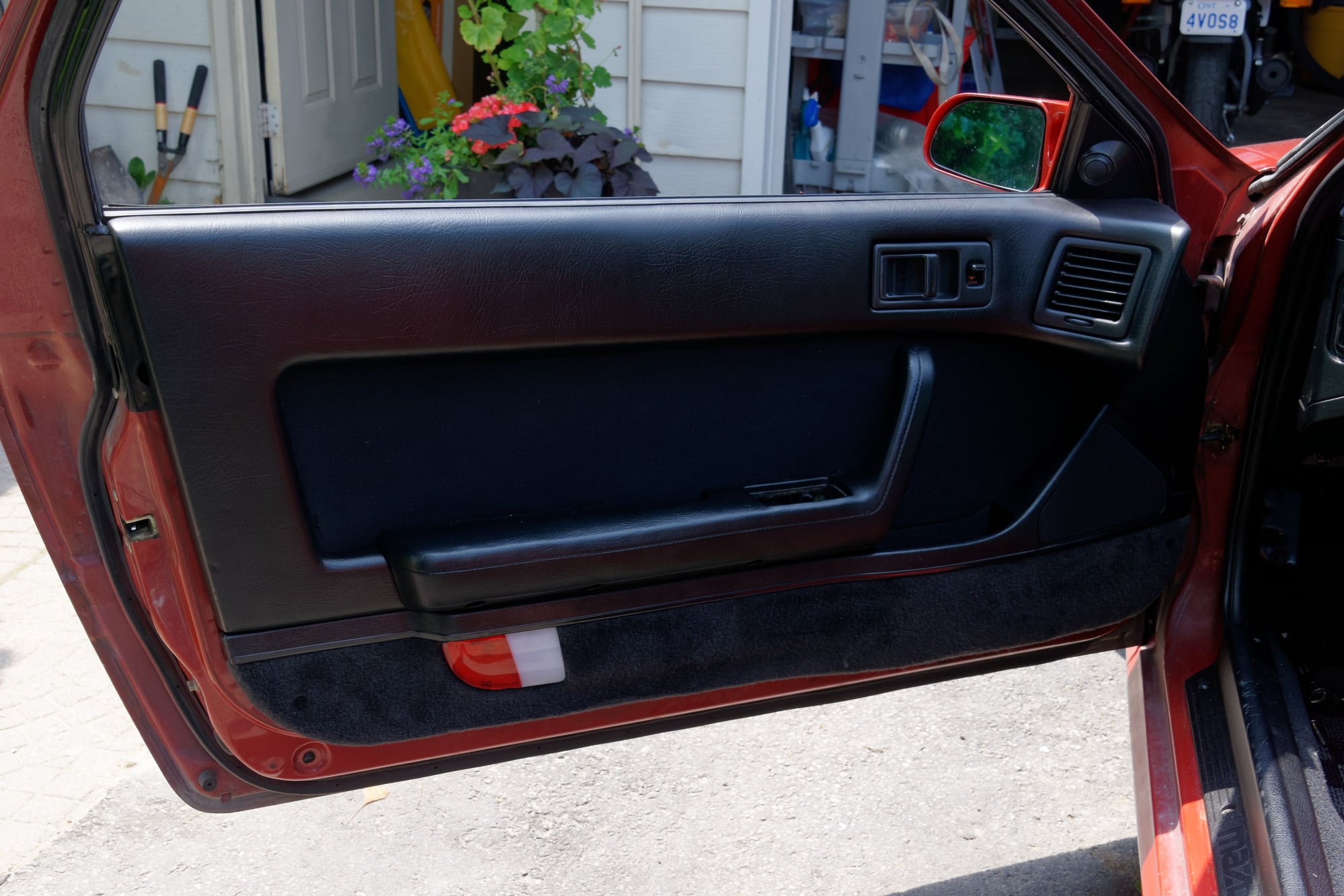
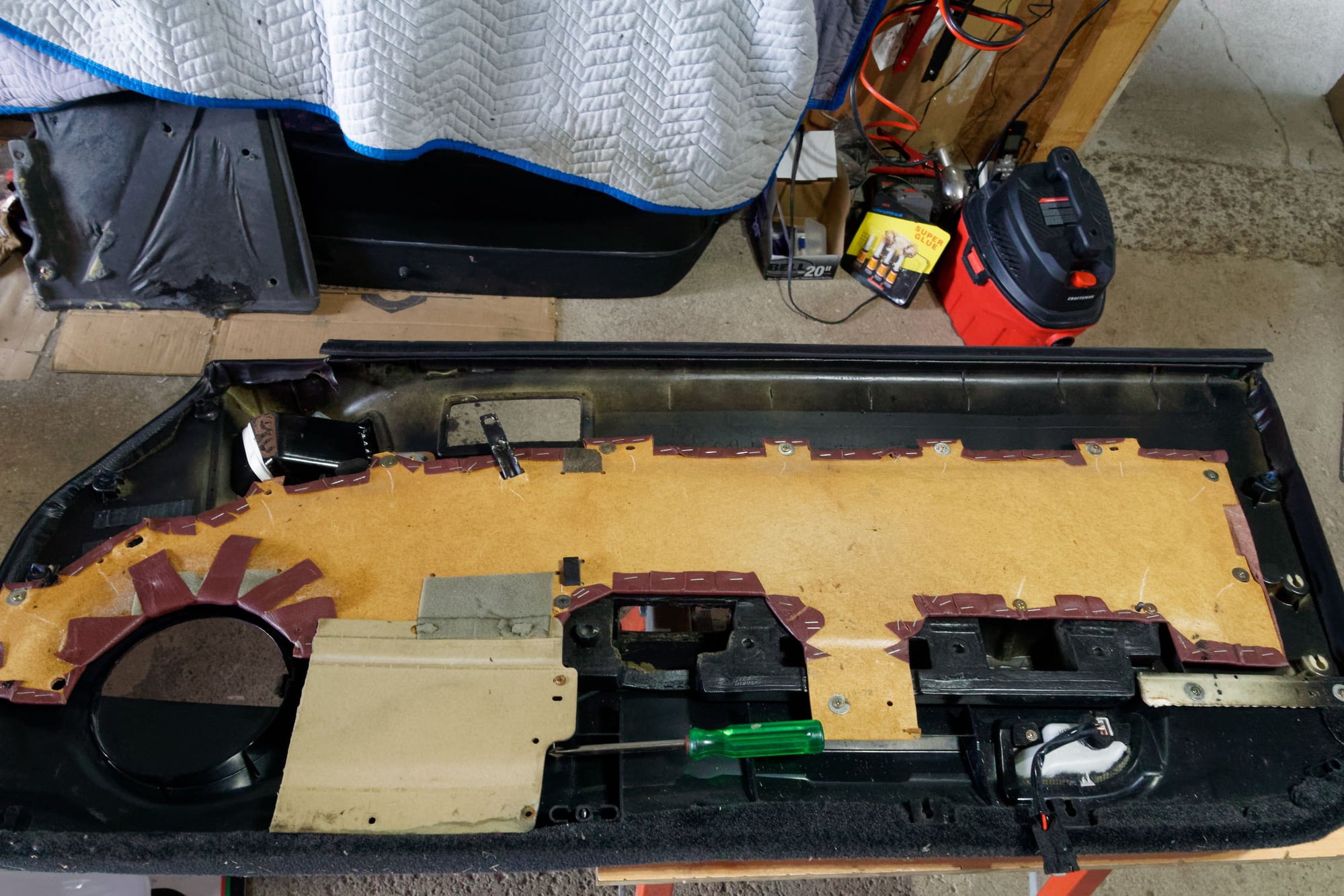
 I had modified the leather insert from my old S4 door when I last assembled these panels, so you can see where I cut back the material for the driver. That would not be nearly enough for this application, but even if it was:
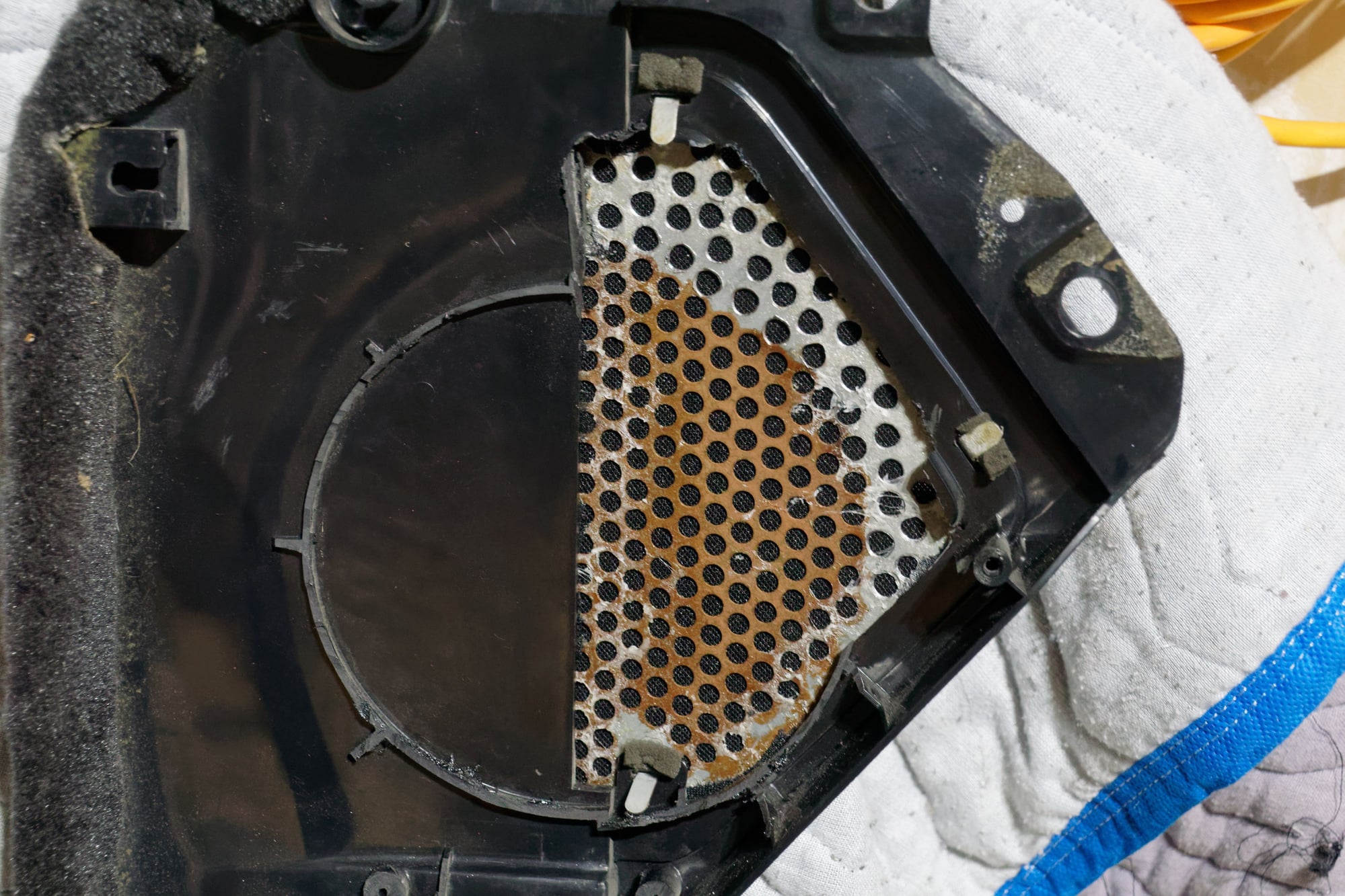
 One thing I should mention in case anyone else is in a similar situation:
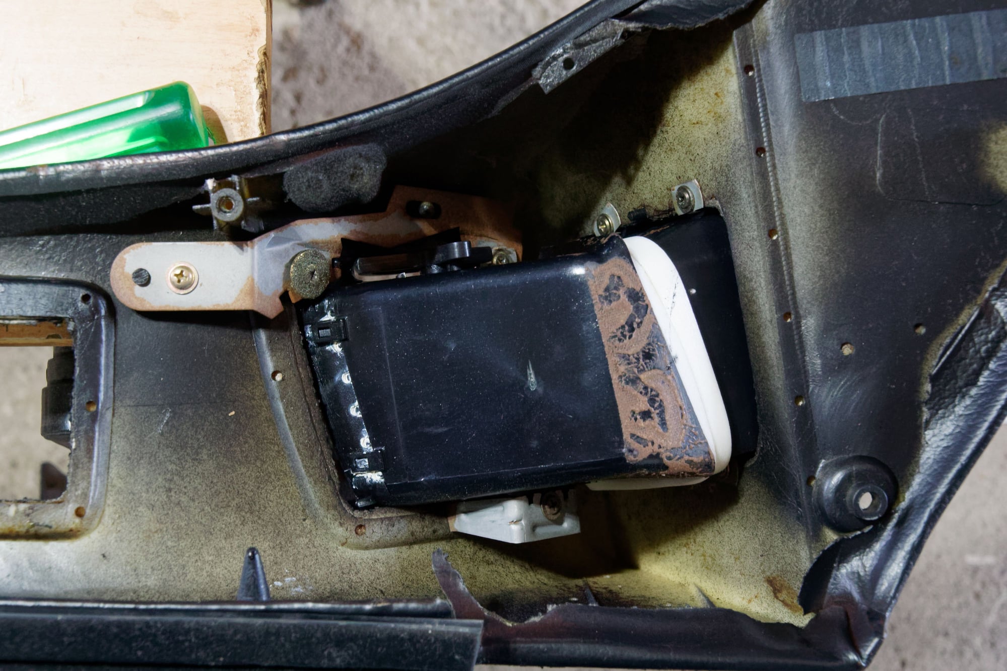
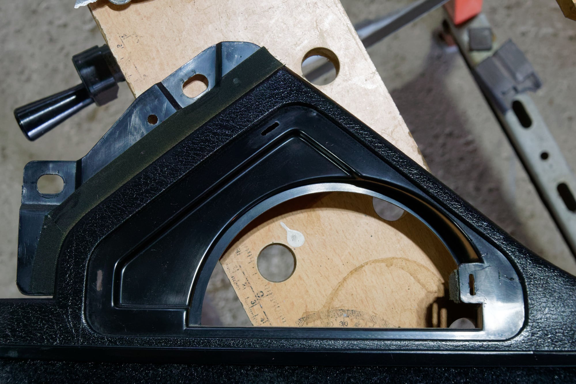
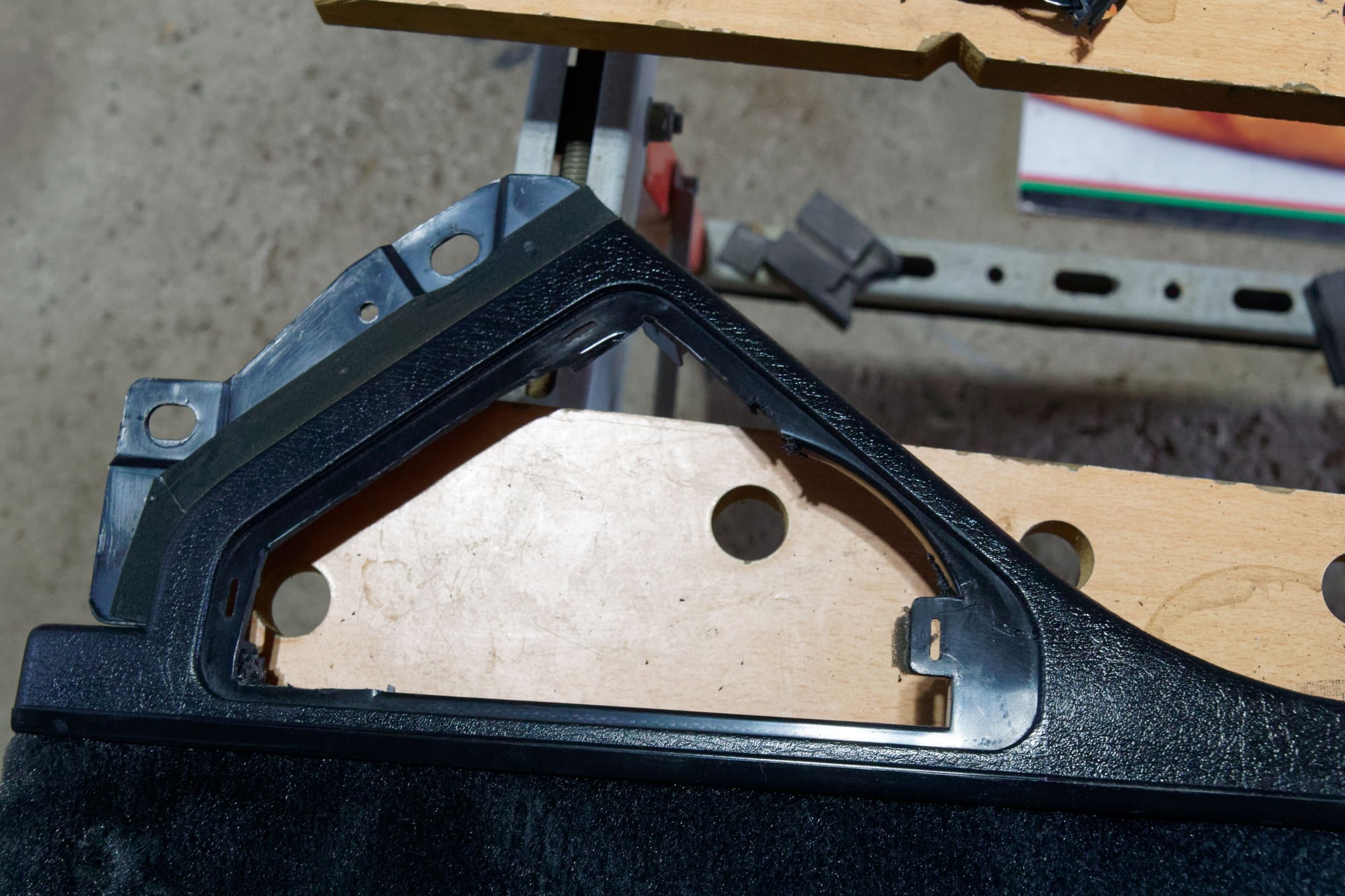
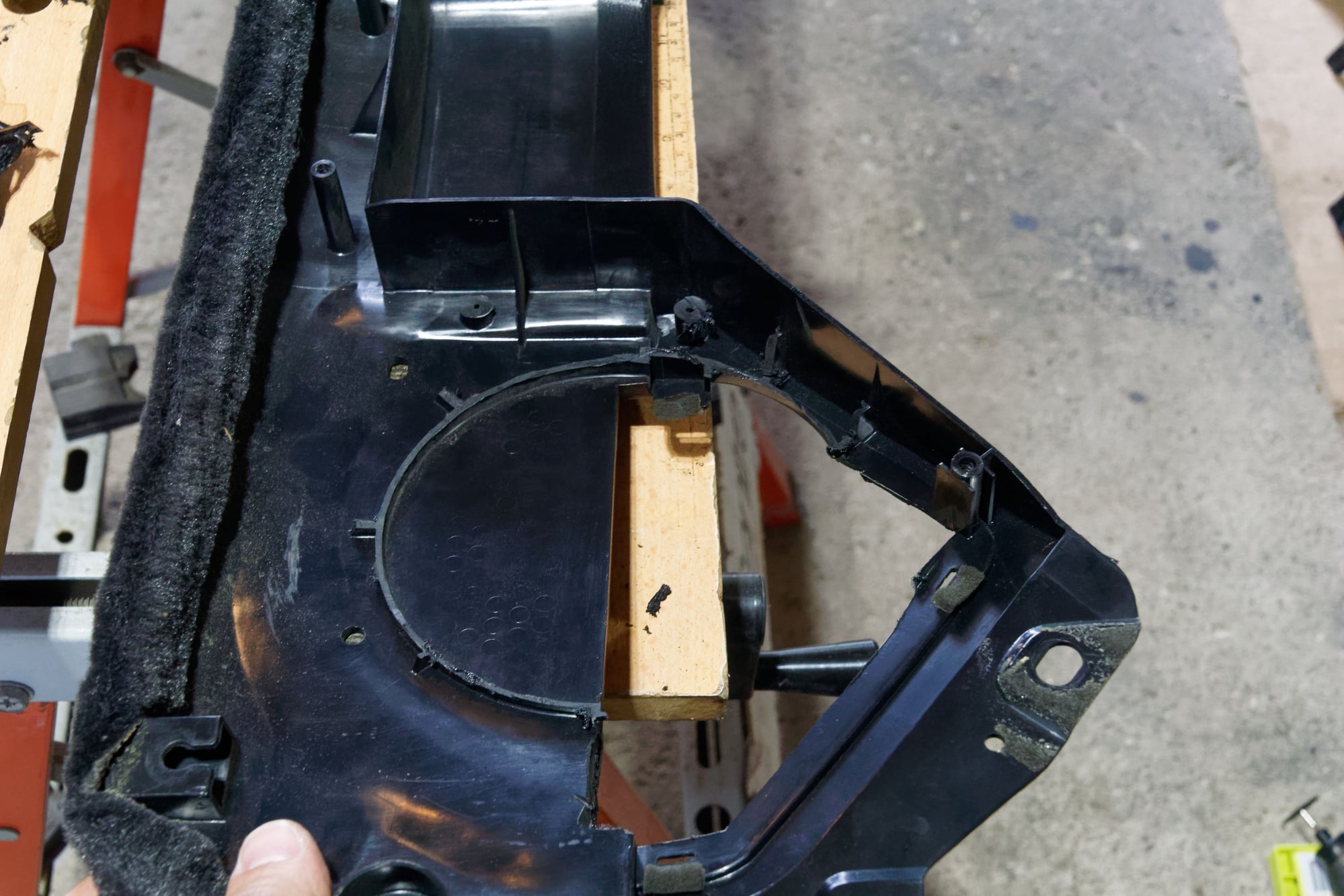

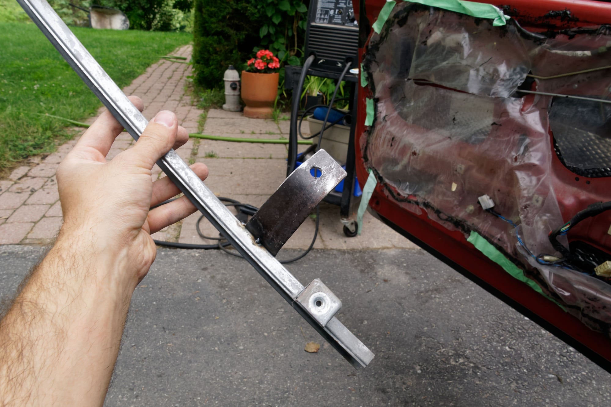
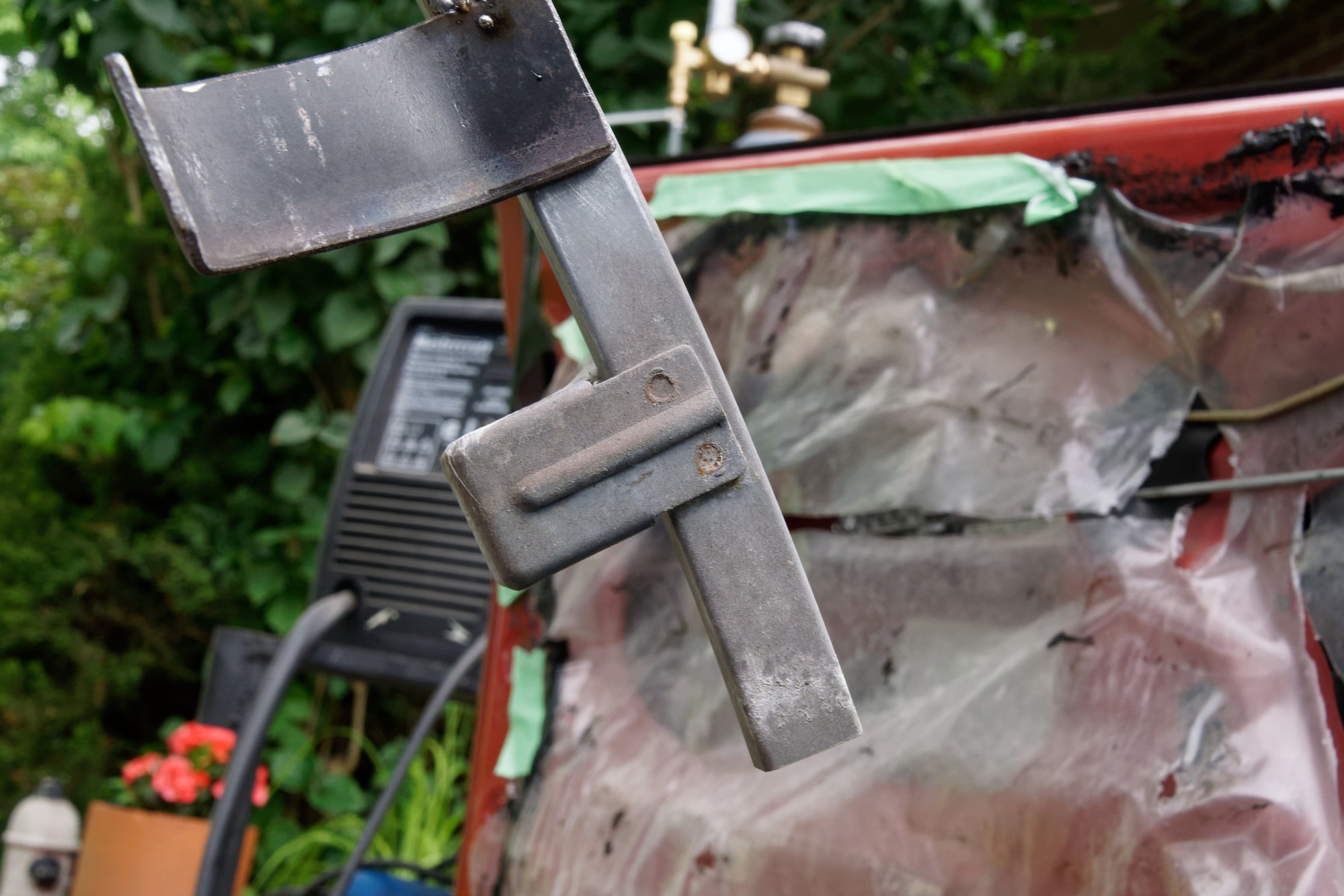
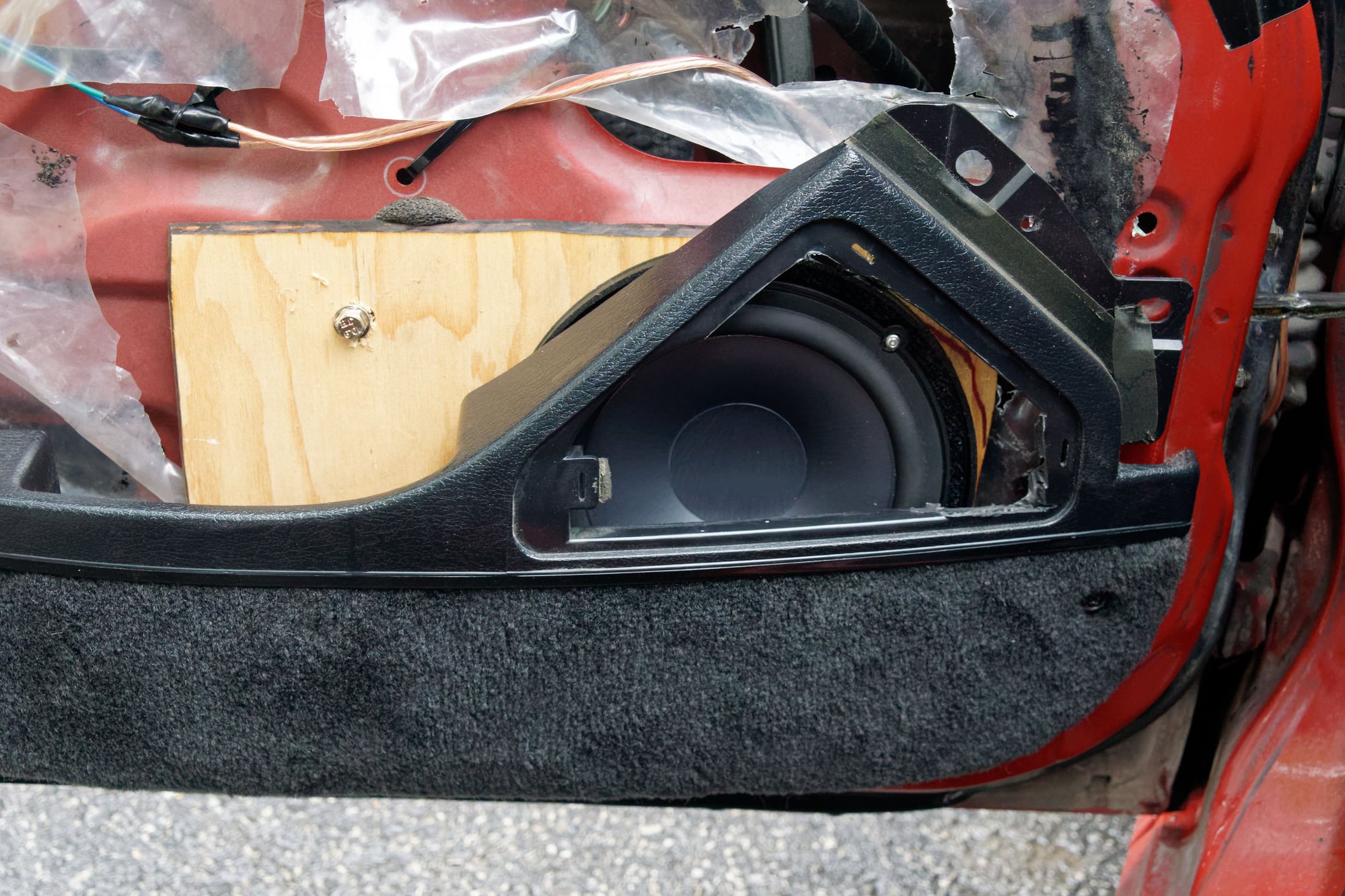
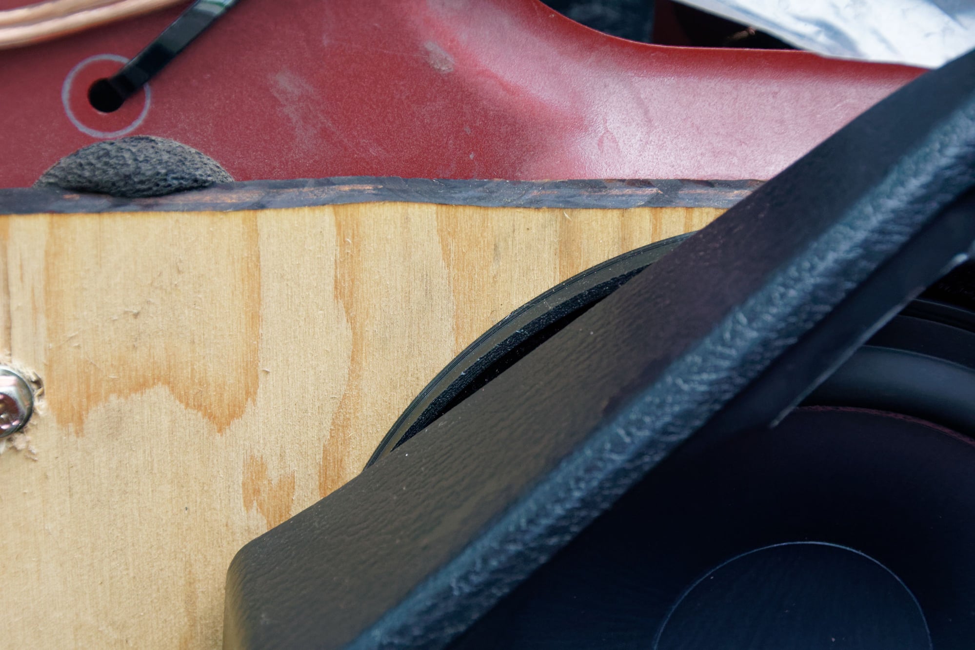
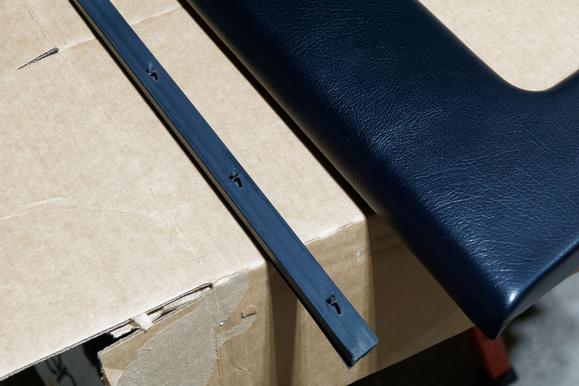
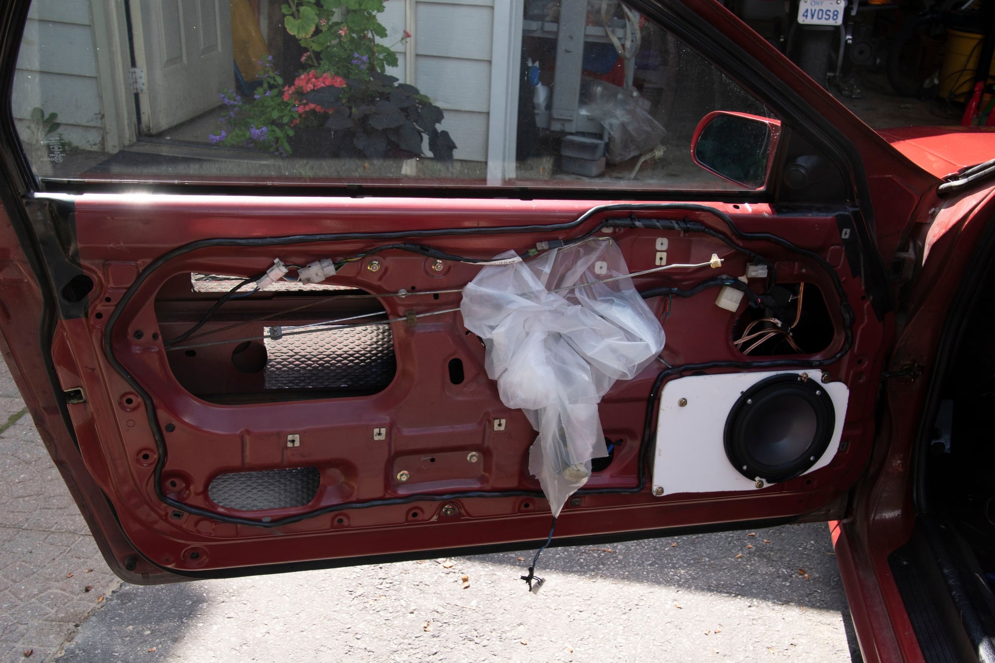
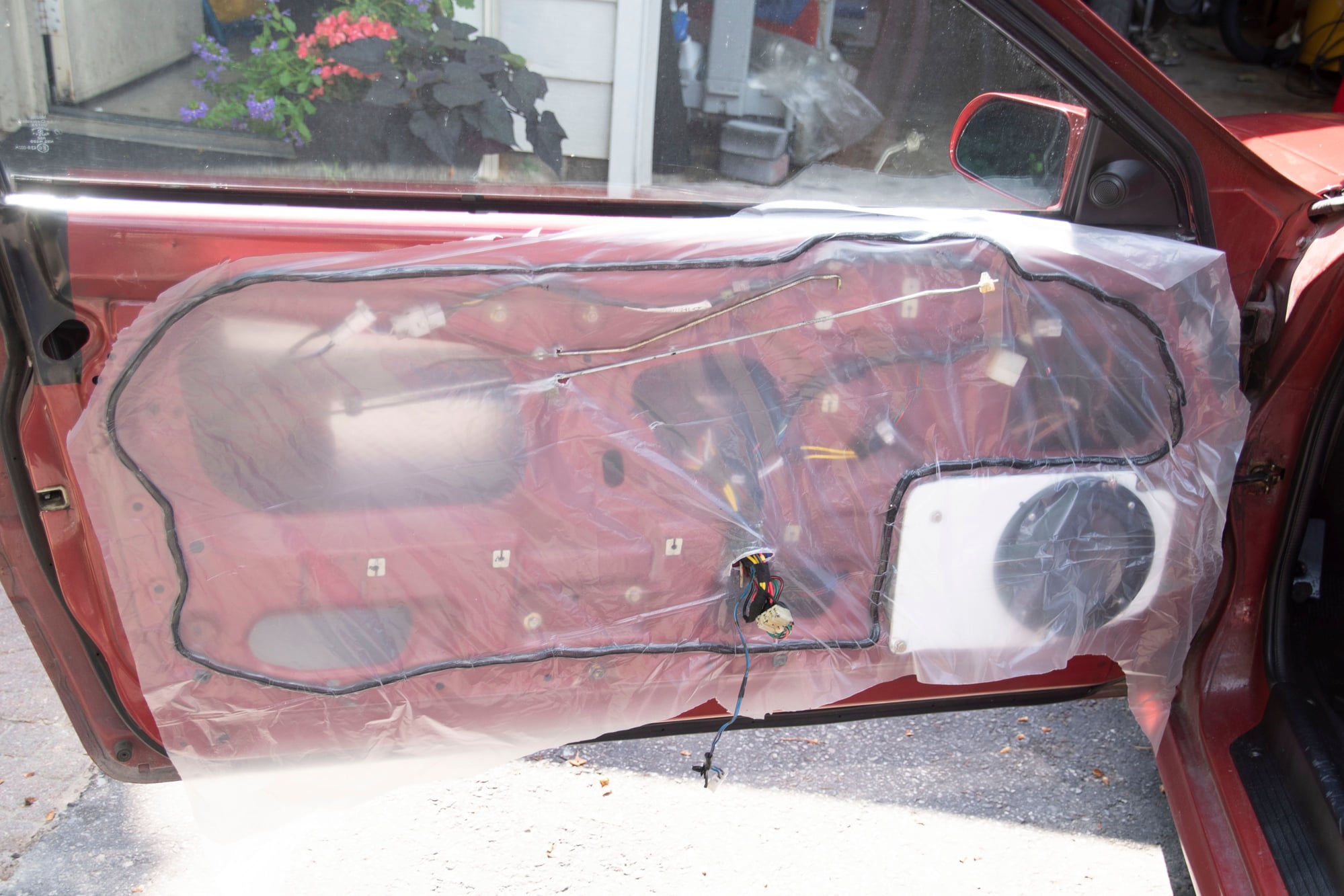
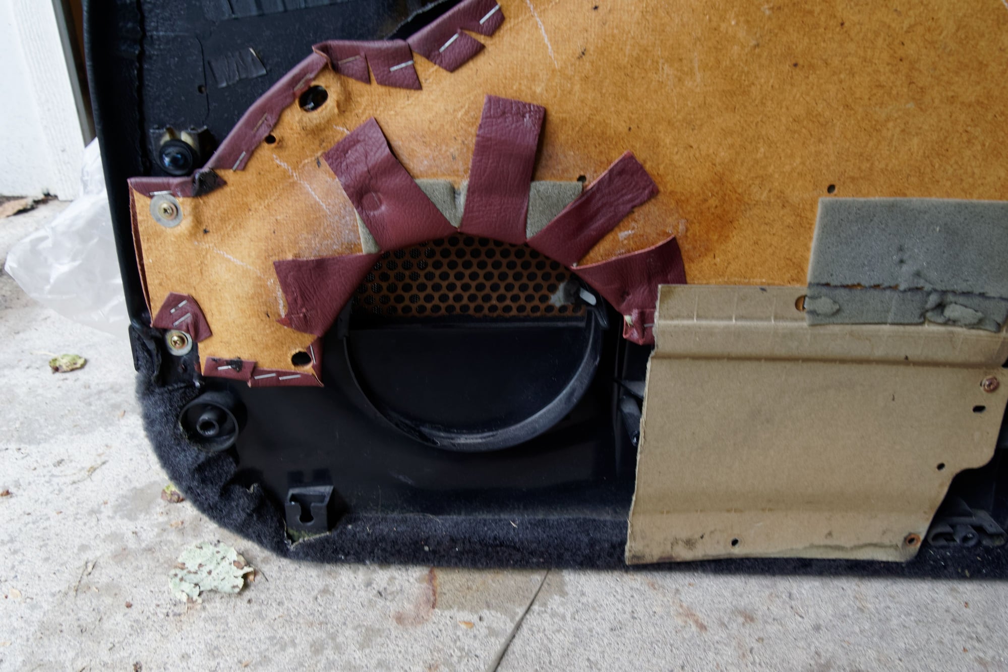
 I spent a long time getting the fitment right. This is not a part that I wanted to screw up, since finding another would be a pain and I wouldn’t have any windows while I waited. I also wasn’t sure how important the precise alignment of this track was, so I erred on the side of caution.